It is possible to find the moment of inertia for any cross-section you like by using the section tool. Select the part you would like to section and select the section tool. Inside of this tool, you should select the box that says, Define Section Tool. Then select the face, edge, or point you want to section about, and ensure that you choose the correct Section tool type to see the cross-section you want. When you see the result you want, press the green checkmark to finish the command. Find th
IronCAD positioning constraints are a great tool for users to position their parts with just a few clicks. These constraints are easy to use and can accurately model how your parts would work with one another in the real world. Fix one of the parts in parent and select the mechanism mode tool. This tool allows you to move the parts by dragging them with your mouse and works with positioning constraints to ensure that your creation has the correct tolerances, and fit.
The Mate and Align tool
IronCAD has several different license types available for use. Each one has a different process for updating the license.
Named User:
Named user licenses can activate their new license by using the serial # and codeword that is located on the license certificate. You will need to go the IronCAD license manager, which can be accessed inside of IronCAD or by searching for that term in your windows search. When you come to the license registration screen, you can select the option
IronCAD offers users a wide range of options for personalizing their product to be look exactly how they like it. In the video below, IronKevin will show you how to change the location of property browsers and catalog browsers for quick access, edit your menu bars to get the tools you need all on the same tab, and how to move your personal settings over to other computers for ease of use.
UI Customization.mp4
If you are a user that likes to fully customize their IronCAD experience with Shortcuts, Ribbon Bars, Etc, and don’t like having to set up the shortcuts between each version, there are ways to bring your settings with you to the new version. In the example below, we will be transferring from 2018 to 2019, so we will copy the XML files located at:
C:\Users\%USERNAME%\AppData\Local\IronCAD\IRONCAD\20.0\Customization
to the new location at:
C:\Users\%USERNAME%\AppData\Local\IronCAD
Here are some quick tips for creating drawing files quickly from your large assembly files:
IronCAD can create drawings that exclude hidden objects from the creation process. Simply hide the parts you don't want to show in a drawing and select the create drawing button. The following Prompt will appear:
This tool is asking if you want to show the parts that you have hidden in your drawing file, selecting Yes will show the hidden parts in the drawing, and selecting no will l
IronCAD’s most powerful tool might have more functionality than you know. In this article we will discuss some of the TriBall’ s functionality to helping you work more efficiently; this list will also include new functionality pertaining to IRONCAD 2019 PU1.
The Triball Consists of a few basic parts: The Inside Handles, The Outside Handles, The Outside Planes, and the Ring. We will discuss each one individually
The Inside Handles:
The inside handles are great tools for Orien
One tool most IronCAD users don’t see is the Surface Reshaping Properties. You can apply this on extrudes to create editable custom shapes. These options range from simple options like capping the end of your extrude, to having the extrude match the surfaces it interacts with.
Cap: Choose a height for the Cap to extend, and IronCAD will create a rounded surface at the end of the extrude.
Cap.mp4
Taper: choose and orientation and tilt angle for selection and IronCAD will cr
IronCAD has a structured BOM mode that allows users to collapse or show specific portions of their scene tree on command. When creating a BOM in ICD, ensure that you select the structured mode in the bill of Materials Style:
When editing the BOM, you will now see an additional column present on the left side that contains + and – that will expand or collapse your BOM.
When you press apply, the BOM will apply your changes and display the BOM as shown in the Edit
Inside an IronCAD sketch you may notice that that there are blue dots whenever you select on a line segment. These blue dots allow you to modify the geometry while maintaining certain relationships with connecting geometry.
On line segments, there is a Blue dot that is offset from the center of the middle of the line, touching the angle dimension. This dot switches sides whenever you select a different side of the line segment. By selecting this and moving your mouse, you will edit t
The Sheet metal loft command allows users to create complex sheet metal geometry with only using two 2D sketches. Ensure that your sketches consist of an open profile and smooth edges so that the part can finish without any errors.
Some options available when using the sheet metal loft command ask you if you would like to choose a profile location. This determines where your sheet metal will be placed relative to the 2D sketches you created. Be sure that you select the correct locati
There is an option inside of IronCAD to see which parts are created from a mirror function. You can activate this indicator by going to the Scene Browser, Selecting the Tree Icon, and selecting more filters. From there you can choose the check mark for Mirror Part or Assembly. That option will show all parts/ Assemblies that are mirrored.
mirrored.mp4
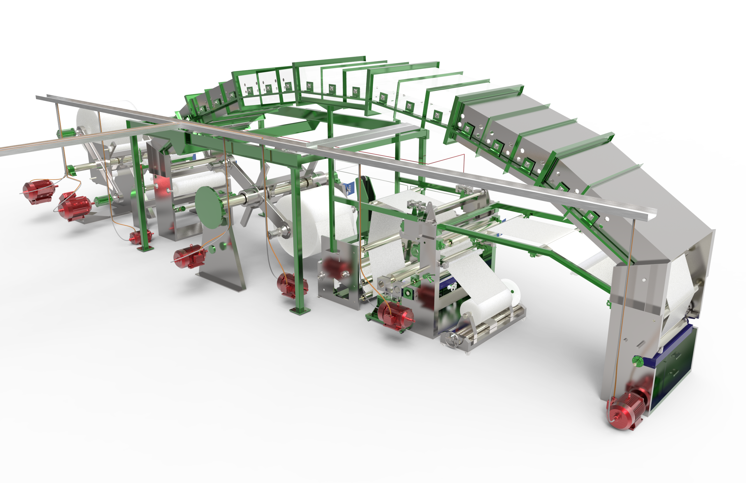
Did you see the new structure part example tutorials on IronCAD.Academy? These videos are a great tutorial to learn about IronCAD’s different design capabilities. For users that are familiar traditional CAD systems, structured part mode can offer a familiar user experience, with the benefit of having IronCAD’s other industry leading features. On top of this flexibility, IronCAD can cover those cases where you may want to use multiple bodies and more of a rigid approach to your part design. This
IronCAD has a partnership with KeyShot, a rendering program that creates beautiful images using an easy-to-use tool and a Real-time rendering scene to show you a preview of your pictures and animations. IronCAD can directly export over to KeyShot using the buttons located in the add-ins section.
The "Render in KeyShot" button will bring up a fresh KeyShot scene file, and will add your parts into it automatically. The "Export to KeyShot" button will create and save a KeyShot file for yo
The IronCAD Web Viewer is an excellent tool for sharing your design with others. Because it only requires an HTML compatible Web Browser, this tool is great for presentations, Websites, and Mobile collaboration. Designers have several tools at their disposal with the Web Viewer, like the ability to hide smaller features for optimal load times and IP protection. Watch the videos below for a demonstration on how to use the tool and a quick video on how to deploy on the cloud or to a local server.
Hi All,
We wanted to follow-up from our previous blog on Dynamic Parametric CAD Design (https://www.ironcad.com/blog/dynamic-parametric-cad-design/) by showing you how to extend this capability with Intelligence. In the video below, we will build a parametric model from scratch and show how easy it is to add intelligence so that you can drop other components onto a parametric model and have them automatically position, orient, and size to fit the parametric model's dimensions. Using Attachm
Importing parts into IronCAD is easy to do. Users can import parts from the following list, note that CATIA V5/V6, Pro/E (Creo), UG/NX, SolidWorks, SolidEdge, JT, Inventor, and IFC require the IronCAD Native translator:
Open a new scene inside of IronCAD, and then use the import geometry button.
Choose from a list of different file types available if you have several files in the same folder, there are several import options available users. Options like the import
Typically in traditional CAD design, when you want to build parts/assemblies that move and size together you would use parameters and constraints. This is a strong capability but can become time consuming especially if you have interchangeable parts or configurable parts. In IRONCAD, there are other methods to achieve a similar approach that can save time and can be used for multiple parts without having to recreate constraints each time a different part is used.
In this blog article video
IronCAD has a whole list of ways to create copies and links of parts. But what if you have externally linked parts in an assembly that you want to use elsewhere or in another design? We will cover the many ways you can do this in IronCAD. Let dive in:
If you want to use a part that exists in a large assembly inside of another design, you can use the save as part/assembly external option from the home menu to create an external linked copy in another location. This tool is very useful for li
IronCAD's conical sheet metal feature gives users a quick method to create a conical shape by simply dragging and dropping it into the 3D Environment and inputting the top/bottom radius and the height. This works well for most design applications for conical sheet metal. However, there are times you will need to input a radius, height, and angle which will drive the other radius value.
In order to do this, a mathematical conversion is done to calculate the radius. For example: Below is an
Configurations:
IronCAD configurations are a powerful tool that allows users to create variations of their content. There are several different options when creating the variations, so be sure to choose the correct type that matches your needs. The different types of configurations are Exploded, Design Variation, Position, and Suppression.
Positioning Configurations:
The most common uses of configurations are to have a quick state to move and hide parts for drawings, or to show moti
Common components reduce the amount of time required for a user to create bulk drawings by connecting pre-created drawings to common parts and assemblies. These common components have preexisting drawings associated with them when used from the IronCAD catalog system in the 3D scene. When you need to make a bulk drawing for your assemblies, the drawings' look and feel will remain consistent for parts that have already have drawings and will update to the changes performed on these parts/assembl
Introduced in IronCAD 2019, IronCAD introduced many changes to our UI. Now the Triball, edges a smooth new look. We heard lots of great feedback about the UI and have decided that users should be able to choose between the classic look and the new UI. The TriBall now has a right click setting to change the styles on the go, so we can use whichever one you like more. We also created a setting in the rendering panel at the bottom on the page to allow users to choose between thick and thin edges. T
Did you know that IronCAD Bulk View creation tool can automatically add dimensions to your views when they are generated?
These dimensions can automatically be created by the IronCAD application with a template that defines which views will have dimensions as well as the properties of the dimensions themselves. To get started, you can create a simple part and then save it to a location on your PC. A simple block is enough to work. Then create a drawing based on that block and add the


 22
22
 9
9