All Activity
- Today
-

How do I permanently remove ChatBot from IronCAD?
Bertrand Kim replied to tgjang's topic in General Discussion
I saw the option permanently turn off about Chatbot for everthing, when I clicked X button. It's definitely annoying and doesn't do anything helpful - it's not even a chatbot(I need to be able to bully). And there's so much information, it feels like reading a book. I don't even want to read it because it's just text. Plz take a look at how other CAD programs are using AI. -
Options - Custom Setting (IRONCAD and CAXA)
Bertrand Kim replied to Malcolm Crowe's topic in General Discussion
Ty so much Malcolm for making these, The default settings of Ironcad&CAXA always weird for me. -
Hi After upgrading IronCAD, I tried to test it, but ChatBot is a bit inconvenient. It is almost the same as F1, the help function, and it pops up from time to time, which is very inconvenient. Thanks.
-

Options - Custom Setting (IRONCAD and CAXA)
Malcolm Crowe replied to Malcolm Crowe's topic in General Discussion
For those interested, attached are our updated custom settings documents for IC2024 PU1. IRONCAD DRAFT - Options - Custom Settings (2024 PU1) - 20240427.pdf IRONCAD - Options - Custom Settings (2024 PU1) - 20240426.pdf - Yesterday
-
Need clarification on conveyor sample design
Cary OConnor replied to tgjang's topic in General Discussion
I'm not sure the conveyor in your image is allowed to be release to customers as it is a customer model. However, here is another conveyor that we use that is from imported data and ok as it is internally created and imported brep from open 3D download sites. ImportConveyor.icc -
Need clarification on conveyor sample design
Bertrand Kim replied to tgjang's topic in General Discussion
Could you please attach that to this post so everyone can see it? - Last week
-
Need clarification on conveyor sample design
Cary OConnor replied to tgjang's topic in General Discussion
The conveyor catalog that we ship is a graphics catalog to show configuations (that will work in COMPOSE and all products). If you need a real geometry catalog, please email me and I can send you a sample demo catalog of real data. -
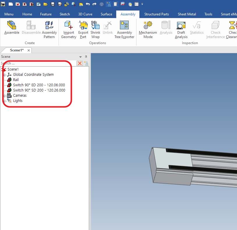
Hi 1. we have a job to do a conveyor demonstration as an ironcad. I looked it up on youtube and the model is very different from the conveyor design videos from about 10 years ago. Is it not possible to use the conveyor catalog from 10 years ago? 2. When I look at the conveyor model tree in IronCAD, the model tree is formed with red icons, not features, and the sub-features are not visible. How can I make the model tree look like a conveyor catalog when the models are so different? Thanks

-
(ATLANTA, Ga.) April 25th, 2024 – IronCAD, a leader in CAD solutions for design productivity and collaboration, is excited to announce the first product update of 2024 for its flagship CAD software. IronCAD 2024 Product Update 1 (PU1) brings significant enhancements and product quality improvements across general modeling, sheet metal design, and collaboration capabilities, designed to accelerate the design process and improve user flexibility in a multitude of engineering environments. In addition, IronCAD is excited to announce the launch of the IronCAD AI Chatbot, a revolutionary new feature designed to enhance user experience and proficiency with IronCAD software. This cutting-edge tool, powered by the latest ChatGPT 4 AI system and backed by an extensive IronCAD database, offers users comprehensive guidance, enhanced learning, and new user guidance on IronCAD’s unique design approach. Read More.. Access Product Updates at https://www.ironcad.com/product-update/2024pu1/
-
(ATLANTA, Ga.) April 25th, 2024 – IronCAD, a leader in CAD solutions for design productivity and collaboration, is excited to announce the first product update of 2024 for its flagship CAD software. IronCAD 2024 Product Update 1 (PU1) brings significant enhancements and product quality improvements across general modeling, sheet metal design, and collaboration capabilities, designed to accelerate the design process and improve user flexibility in a multitude of engineering environments. In addition, IronCAD is excited to announce the launch of the IronCAD AI Chatbot, a revolutionary new feature designed to enhance user experience and proficiency with IronCAD software. This cutting-edge tool, powered by the latest ChatGPT 4 AI system and backed by an extensive IronCAD database, offers users comprehensive guidance, enhanced learning, and new user guidance on IronCAD’s unique design approach. The IronCAD AI Chatbot provides instant, personalized assistance directly within the IronCAD interface, offering tips, best practices, and tailored support for all IronCAD-related queries. Accessible through the Help Ribbon Bar or the AI icon, the Chatbot is set to become an indispensable resource for new and seasoned users. Initially available to select partners and customers, the IronCAD AI Chatbot will be fully launched to all users later this year. Once released, the Chatbot will be offered free of charge for a limited time, with future license options based on usage to accommodate company needs. Innovations for Enhanced Design Flexibility and Productivity Known for its user-centric design and flexibility, IronCAD continues to push the boundaries of mechanical CAD software (MCAD) by providing solutions that are both innovative and intuitive. This latest update introduces several key enhancements and quality improvements that empower users to achieve greater creativity and efficiency. Key features of this update include: Advanced General Modeling Tools: Enhanced feature-level linking capabilities allow users to create links from feature selections on parts and offers quick creation of links on drop from the IronCAD catalogs streamlining the creation process. The introduction of lock mechanisms for parts and assemblies is designed to prevent unintended alterations, securing the design data in its current state and safeguarding against unauthorized edits. Sheet Metal Design Enhancements: IronCAD 2024 PU1 improves the drag-and-drop behaviors for the sheet metal stock thickness selection process and introduces new bend line styles and layer support for up and down bend lines, enabling more precise detailing of sheet metal parts for manufacturing. Advanced Sketching Options: New sketching options, such as the ability to hide unedited parts and display hidden sketch items as dashed lines when obscured by geometry, provide a cleaner, more intuitive sketching environment. Structured Parts Enhancements: The update introduces new tools for structured parts, including decimal precision settings for BOM properties on structured frame members and an option to exclude hidden bodies from BOM, ensuring more accurate and tailored documentation. Expanded Collaboration Features and Integration Enhancements: IronCAD 2024 PU1 expands its support for KeyShot 2024 and enhances the IronCAD Native Translator capabilities for the latest file types, including CATIA, SolidWorks, and its Architectural and Viewing Translator Plus for the latest BIM formats, IFC and Revit, streamline cross-platform collaboration and ease the integration of IronCAD into diverse workflows. Customer Driven Quality Improvements: In IronCAD 2024, we’ve prioritized customer-driven quality improvements based on feedback from our community. Stability, reliability, and performance quality improvement further enhance the overall experience. IronCAD remains committed to excellence, continually evolving to meet the needs of our users. IronCAD’s Product Update 1 is tailored to empower users to unleash their creativity through cutting-edge technology, user-friendly design tools, and enhanced flexibility in design. The update enhances IronCAD’s already powerful tools, providing the flexibility to create, modify, and manage complex designs more efficiently than ever. “At IronCAD, we’re dedicated to making CAD as intuitive and versatile as possible,” said Cary O’Connor, Vice President of Marketing at IronCAD. “These enhancements are driven by feedback from our community and our deep understanding of the challenges our users face. We continually strive to develop solutions that not only meet but exceed their needs, and our latest update is a testament to IronCAD’s commitment to this mission, offering tools that are not only powerful but also intuitive, ensuring that engineers and designers can achieve their best work with ease and precision. And now, with the introduction of the IronCAD AI Chatbot, we’re taking another leap forward in providing innovative solutions to our users that enhance user experiences and provide a foundation for future groundbreaking developments,” he added. IronCAD 2024 Product Update 1 is available for immediate download for all current IronCAD users. New users are invited to explore IronCAD’s diverse capabilities through a free trial on the IronCAD website. For detailed information on all the new capabilities and enhancements included in the IronCAD 2024 Product Update #1, please visit IronCAD’s website or your local IronCAD distributor. About IronCAD IronCAD delivers high-performance design collaboration solutions that free engineers from the constraints imposed by traditional CAD systems. IronCAD enables designers to translate their ideas into reality through its innovative design methodology and its commitment to providing strong, customer-focused solutions in the CAD industry. IronCAD’s mission is to blend its ingenuity and engineering expertise to develop a software suite that not only meets but exceeds the expectations of our global clientele, driving innovation and excellence in the engineering community. The post IronCAD Announces 2024 Product Update 1 Featuring AI Integrated Chatbot and Improved Capabilities for an Enhanced Design Experience first appeared on IronCAD CAD Software Solutions. View the full article
-
IronCAD 2024 Product Update 1 (PU1) brings significant enhancements and product quality improvements across general modeling, sheet metal design, and collaboration capabilities, designed to accelerate the design process and improve user flexibility in a multitude of engineering environments. In addition, IronCAD is excited to announce the launch of the IronCAD AI Chatbot, a revolutionary new feature designed to enhance user experience and proficiency with IronCAD software. Key features expand across the 3D Design, including Innovative and Structured Design, Sheet Metal Design, and Collaboration in Import/Export. Below are the key features included in IronCAD 2024 Product Update 1: Intelligence IronCAD AI ChatBot General Modelling Create Link from Selection – Feature Level Link Support Lock Part/Assembly Reset the Selection Filter Option on Selected Filters with ESC Face Section for Inner and Outer Faces Select All Smoothly Connected Faces with Tab Key Extrude Selected Faces (Multiple) to Distance Width Advanced Constraint Support Selection of Faces from Multiple Parts Sheet Metal Drag and Drop Sheet Metal Thickness/Material Behavior Improvement Sheet Metal Bend Line Style/Layer Support Up/Down Custom Intellishape Properties Transfer to Unfold Geometry Sketch Hide UnEdited Part Display Option to Display Hidden Sketch Items as Dashed Lines Structured Parts Create Sketch Command on Datum Planes Structured Frame Support for Decimal Settings on BOM Properties Hidden Body Option to Exclude from BOM Extrude Features Support for Multiple Bodies Collaboration KeyShot 2024.1 Support IronCAD Native Translator, support for the latest file types Architectural & Viewing Translator (“A&VTransPlus”) File Types SolidWorks Drawing Import into 3D Scene as Facet 2D Reference Intelligence IronCAD AI ChatBot We’re thrilled to announce the launch of the IronCAD AI Chatbot, a revolutionary new feature designed to enhance user experience and proficiency with IronCAD software. This cutting-edge tool, powered by the latest ChatGPT 4 AI system and backed by an extensive IronCAD database, offers users comprehensive guidance, enhanced learning, and new user guidance on IronCAD’s unique design approach. The IronCAD AI Chatbot provides instant, personalized assistance directly within the IronCAD interface, offering tips, best practices, and tailored support for all IronCAD-related queries. Accessible through the Help Ribbon Bar or the AI icon, the Chatbot is set to become an indispensable resource for new and seasoned users. Initially available to select partners and customers, the IronCAD AI Chatbot will be fully launched to all users later this year. Once released, the Chatbot will be offered free of charge for a limited time, with future license options based on usage to accommodate company needs. General Modelling Create Link from Selection – Feature Level Link Support Extending the new capabilities added in IronCAD 2024 for Creating Links from Selections on Parts and Assemblies, PU1 now adds support for the Feature Level. Simply select multiple features and right-click in the scene or scene browser to access the Create Link option. This is only supported on features of the same part and on IntelliShape features (modification features are not supported, such as Blend, Chamfer, Boolean, etc). Lock Part/Assembly A new option has been added to Lock a Part or Assembly completely. This is more powerful than the Prevent Selection function because it does not allow any modifications (including Drag & Drop new features). This option is found in the right-click menu on a part or assembly under the Interaction menu. The Prevent Selection option allows adding features to the parts/assemblies. The lock will attempt to prevent all operations except structure changes, such as assembling/disassembling. Reset the Selection Filter Option on Selected Filters with ESC A new option in the Tools-Options-Interactions under Feature Behaviors has been added to allow the ESC key to reset the selection filter (in the bottom right of the IronCAD interface) to Any. Users can select filters like Face selection (and some commands like Blends can set Face filters automatically) and can now hit ESC to reset the filter to Any once done with selections. Face Section for Inner and Outer Faces In the Selection Filter (at the bottom right of the IronCAD interface), two new options have been added for the faces to select the inner and outer faces. Select a face that has an inner or outer pocket, for example, and these new filters will select all the faces of the inner/outer pocket. The face selected for determining the inner and outer faces will not be returned in the selection. Select All Smoothly Connected Faces with Tab Key Similar to the Tab Key on an Edge to select the smooth connected edges, the tab key can be used on a face to select all the smoothly connected faces on a part. Extrude Selected Faces (Multiple) to Distance A new capability has been added to multiple selected faces to create an extrude from the selection. Once multiple faces are selected on an individual part, right-click and select Extrude Selected Faces. This will create multiple extruded features from each selected face at a distance specified by the user. Note this only works on planar faces located on the same part. Width Advanced Constraint Support Selection of Faces from Multiple Parts The Advanced Positioning Constraint, Width, has been enhanced to allow the selection of faces from different parts. This allows the user to easily create a width constraint on parts based on faces from different parts. Sheet Metal Drag and Drop Sheet Metal Thickness/Material Behavior Improvement When reusing sheet metal parts, a new behavior has been added for the dropping pop-up dialog to select the sheet metal thickness. If the sheet metal shape only contains a stock (The default “Stock” in the bottom Image below is an example), the dialog will be invoked on the drop to allow users to select the thickness. If the sheet metal part contains bends, this dialog will not appear and retain the previous set thickness. Sheet Metal Bend Line Style/Layer Support Up/Down New Style and Layer settings have been added in the IronCAD Drawing (ICD) to set the Line Type and Layer for the Up and Down Bend Lines. This option is for the Bend Line Style. These options allow users to set different layers and lines to denote up and down bend lines for manufacturing. Custom Intellishape Properties Transfer to Unfold Geometry Sheet Metal Unfolds can now adopt Custom Properties applied to IntelliShapes on the folded sheet metal. These properties allow users to set Custom Property Mapping to place elements on different styles and layers for manufacturing. Custom Properties set on the folded part will automatically copy to the unfolded sheet metal part. Sketch Hide UnEdited Part Display A new setting on the display settings in the 2D Sketch for “Hide UnEdited Part” has been added to allow for better visibility when editing 2D Sketches. This setting will hide parts that may appear in front or behind the edited 2D Sketch, making it easier to see the sketch and edited part geometry simultaneously. Option to Display Hidden Sketch Items as Dashed Lines 2D Sketches will often appear behind parts in the scene, making it difficult to find or visualize the sketches. A new setting has been added to show these hidden sketches as dashed lines. In addition, users can directly select these dashed lines to select the sketch through parts for editing access. Structured Parts Create Sketch Command on Datum Planes In the right-click menu, a new option has been added to Structured Part Datum planes to create a sketch on the selected datum. This setting makes it faster to create a 2D Sketch on a datum which is a common process in structure part designs. Structured Frame Support for Decimal Settings on BOM Properties Users can now set the decimal precision for properties sent to the BOM for Structured Frames. In the Tools-Options-Parts, users can specify the desired decimal precision. Hidden Body Option to Exclude from BOM A new tools option under Tools-Options-Parts has been added to exclude hidden bodies in the BOM. This is used for the Body Properties in the BOM setting on Structured Part Bodies. Extrude Features Support for Multiple Bodies When creating Extrude Features on Structured Parts, users can now apply the extrude to multiple bodies. Default behaviors for Extrude Thru All will automatically select multiple bodies to the fullest extent. Collaboration KeyShot 2024.1 Support IronCAD 2024 Product Update 1 now supports the latest release from KeyShot, 2024.1. IronCAD Native Translator, support for the latest file types The IronCAD Native Translator Add-on extension has been updated to support the latest file formats from several of the most common 3D CAD systems on the market. Import now supports; CATIA V5: V5R8 – V5–6R2024 Pro/E (CREO): 16 – Creo 10.0 UG NX: 11 – NX 2312 Inventor: V11 – V2024 SolidWorks: 98 – 2024 SolidEdge: V18 – SE 2024 JT Import: 8 – 10.2, 10.3, 10.517, 10.618, 10.718, and 10.826 IFC: IFC 2×3, IFC 4×1, IFC 4×2 Rhino: V2-8 DXF/DWG: 2.5 – 2024 Architectural & Viewing Translator (“A&VTransPlus”) File Types The IronCAD Architectural & Viewing Translator (“A&VTransPlus”) Add-on extension has been updated to support the latest file formats. Revit Read – Version 2015 to 2024. Revit Write – Write is only to Revit 2024. *Note: The current release of Revit Write is unsupported for support until a future release update is announced. IFC Read/Write – IFC2x3, IFC 4×1, IFC 4×2 For the GLTF Writer added to the standard product, the write version is: GLTF Writer – Version 2.0 SolidWorks Drawing Import into 3D Scene as Facet 2D Reference As part of the Architectural & Viewing Translator (“A&VTransPlus”) add-on, users can now import SolidWorks Drawing files (slddrw) into the IronCAD Scene as a Facet Reference of 2D Curves. This is strictly for visualization or viewing of SolidWorks Drawings. Future support may be added to access real curve information once provided from IronCAD’s provider. The post What’s New in IronCAD Design Collaboration Suite 2024 Product Update 1! first appeared on IronCAD CAD Software Solutions. View the full article
-
Malcolm. Thank you very much for the answer to my question. I'm glad to see that IronCAD is finally making some changes. However, it is still lagging a lot while other low-cost CAD systems (SolidWorks, Inventor, Gstar CAD, ZW CAD, Brics CAD, UniCAD, NanoCAD, Smart CAD...) are growing rapidly. If IronCAD wants to grow while AutoCAD is so prevalent in the world, it will either have to abandon ICD and use that money to improve IC and CAXA intensively, or join the ODA and focus its efforts on developing AutoCAD-compatible 2D tools. Here are the IronCAD features that users need most. 1. Dual Monitor support 2. Active Sub Assembley When creating a part, the part will only be created under the active Sub Assembly. 3. Improved convenience of Multi Body Modeling and ease of designing steel structures, etc. Thanks.
-
 MBBM KOREA joined the community
 -
Hi TaeGyu, There have been positive improvements regarding Structured Frames within recent releases, and there are many potential applications for it; but in my opinion additional enhancements are needed before I'd start showcasing it to users. Perhaps some of those enhancements will arrive in IC2024 PU1 or IC2025 or ....... (I don't know what R&D are working on). In answer to your questions. 1. Sometimes I like to toggle between displaying and exporting Solids and 3D Curves (as part centerlines). This is a huge benefit offered by Structured Frames (and Structured Parts). In these applications I will include 3D Curves, but these are normally "Extracted 3D Curves" from a 2D Sketch. 2D Sketches provide better control and can be driven using parameters. While the 3D Curve tools have been greatly improved recently, they also require additional enhancements to provide the level of control needed. As a result, these aren't my preferred tools. 2. It is very rare that I need to create a Datum Plane (but I'm pleased to have the capability for when I do). You don't need Datum Planes to create 2D Sketches. For example, in your model the Datum Plane wasn't necessary, as the "Sketch Position" tools provide that positioning functionality relative to the XY, XY, and YZ Planes of the Part. 3. For some projects we export the CAXA BOM to Excel Spreadsheets for the reasons that you have listed. All of our BOM Styles contain all of the properties that we might want to display or export. But we control what is displayed in the drawing by controlling the width of the BOM item within the BOM Style. A width of zero (0) means that it doesn't display. Regardless of what is displayed in the BOM on the drawing, when the BOM is exported from CAXA, all of the columns are exported to the Excel Spreadsheet. Malcolm
-
Malcolm. Your sample video is very helpful for me. I personally find the Steel Structure feature in IronCAD very difficult and frustrating, so I have never tried to apply it to structures and have only modelled IronCAD stapler samples. But when I see what you have designed with the Steel Structure feature of IronCAD, it is even phenomenal. Questions. 1. when designing and modelling the structures in your video, did you use 3D Curve to design the layout and then design the structures? 2. when designing a steel structure, do you create a Datum Plan and create a 2D curve there and create a Steel Structure? 3. When calculating the BOM, do you export the BOM Table in CAXA 2D Drawing to Excel File and use the file to create documents such as quotation, order, purchase requisition, etc. I am developing a C++, C# programme to extract BOM information from 3D Scene files and automatically issue quotations, purchase orders, purchase requisitions, etc. by company and item.(Only Innovate Mode Model)
-
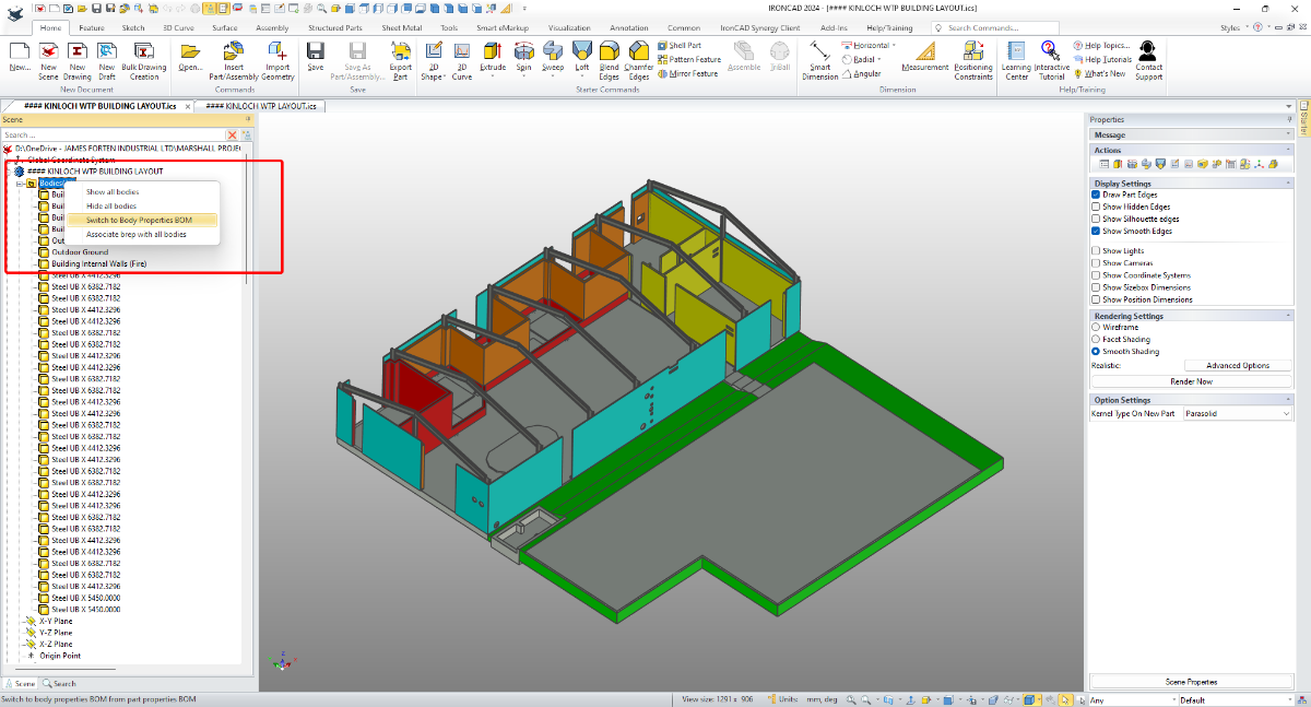
Hi TaeGyu, I'm pleased that it helped. Regarding any Application being written for extracting Part Properties from multi-bodied Structured Parts, it's important to reference the "Switch" between Part and Body Properties. This "Switch" was introduced in IC2024. It you're not familiar with this, see the attached video. Malcolm Switch Between Part and Body Properties BOM.mp4

-
Thank you very much. Malcolm You have solved my this problem again. Now all I need to do is ask the IronCAD R&D Team for a C Program API to access the Attribute (Matrical, Qty, Size, Colour, etc) for the Body. I need to create Purchase Orders, Purchase Requisitions, and Quotations in PLM with a batch aggregation of parts. Thanks.
-
Hi TaeGyu, In the attached video I demonstrate how to apply the requested properties (Description and Material) to the individual Frame Members (Bodies) of the 3D model, so that they then appear in the BOM of your CAXA drawing. I also show how to get the Qty to display and total correctly within the BOM. I hope this points you in the right direction. Malcolm Structured Frames - Bodies in BOM.mp4 STEEL_TEST - MC.exb STEEL_TEST - MC.ics
-

woodlab for technological furniture production CNC
dleczynski replied to dleczynski's topic in General Discussion
New big library for desing cabinet. https://www.woodlab.com.pl/pobieranie/program/Modele3D.zip -
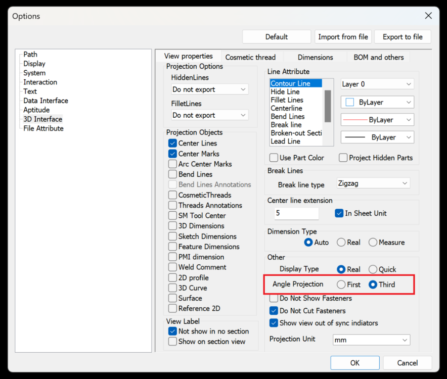
I didn't see a post that talked about Third Angle Projection in Standard View in CAXA, so I'm writing about it here. Options -> 3D Interface -> Angle Projection
-
Hi I am trying to sell IronCAD as an alternative to AutoCAD to tier 1 and 2 vendors for ship building companies and plant builders. So I tried to do a very simple sample using the IronCAD Structured Parts module, and it was very difficult compared to Solid Works or Inventor, but it's not a problem that I can't get them to design in Innovate Mode, because there are a lot of cases where the whole structure needs to be driven by a skeleton. Also, I am developing PLM, and I have programmed the part designed in Innovate Mode to automatically create quotation, purchase request, purchase order, etc. by aggregating part number, part name, description, quantity, and material, but I cannot apply it because description, material, quantity, etc. are not displayed in Structured Parts. I would be very grateful if some one could tell me how to design in Structured Parts Mode and how to display Description, Material, Quantity, etc. Also, I've mentioned this a few times before, but dual monitor support is very important for ship builders and plant companies to display 3D and 2D on different monitors. Thanks. STEEL_STRUCTURE.zip SW 2016 - Converting Multi-body Parts to Assembly.mp4
- Earlier
-
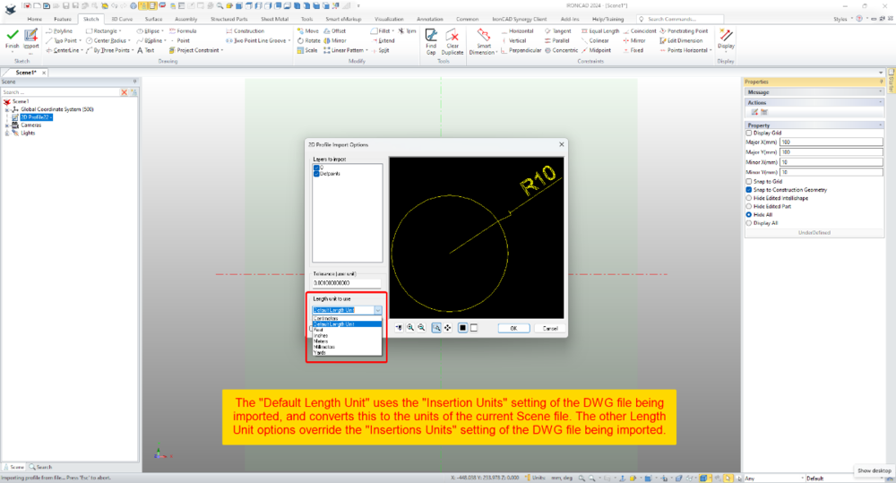
Within 2D Profiles (sketches) it's possible to import geometry from existing DWG files. Within the Import Options Dialog there is the ability to set the "Length Unit to Use". This selection relates to the source file (not the current Scene) and influences the size of the imported geometry. When the "Default Length Unit" is selected, IRONCAD uses the "Insertion Units" setting of the DWG file being imported; and converts this to the units of the current Scene file. If geometry in the DWG file has a length of 10 inches (that is, 10 units set to inches using the "Insertion Units" setting), then IRONCAD will convert the 10 inches into 254 mm (if the Scene units are set to mm). So, it helps being aware of the INSUNITS setting in DWG files. When the other Length Unit options (Centimeters, Feet, Inches, Meters, Millimeters, Yards) are selected, these override the "Insertion Units" setting of the DWG file being imported. So, if the original DWG has geometry with a length of 10 inches, but within the import options the "Length Unit" is set to millimeters, then IRONCAD will treat those original 10 inches as 10 mm instead. This is demonstrated in the attached video, where DWG files using different "Insertion Units" settings are imported into a 2D Profile (sketch). Malcolm 2D Profile Import Options - Length Unit to Use.mp4 DWG Setting - Insertion Units - Inches.dwg DWG Setting - Insertion Units - Millimeters.dwg DWG Setting - Insertion Units - Unspecified.dwg
-
I can't handle it
-
Kevin & Jonas, Thanks for the info. I had split another assembly out of the original troublesome file and it is having the same issue. I will try your trick and see if that works. Fortunately I had no external links in the files.
-
Can you send your model to support@ironcad.com and we can investigate if it is related to that model?
-
woodlab for technological furniture production CNC
dleczynski replied to dleczynski's topic in General Discussion
faster desing by fast drag and drop