

Sheet Metal Loft

Entry posted by BSTAFF
1,336 views
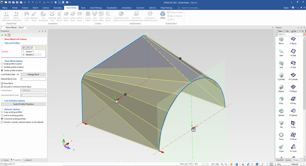
The Sheet metal loft command allows users to create complex sheet metal geometry with only using two 2D sketches. Ensure that your sketches consist of an open profile and smooth edges so that the part can finish without any errors.

Some options available when using the sheet metal loft command ask you if you would like to choose a profile location. This determines where your sheet metal will be placed relative to the 2D sketches you created. Be sure that you select the correct location when starting, or you might have to right-click the part later on and switch the location. You can also choose to change the sheet metal stock used for the loft and the features that will come after creation. If you didn't select the correct stock, you could always edit it later on by right-click – part properties.
Default bend lines are an essential property when creating a loft that has gradual turns and curves. This tool will do what it says; determine the number of bends to be used when approximating these bends. This will be noted on the unfolded part for manufacturers to follow.
The press bend command can be used to make a press break developed part. You can choose the parts minimum bend radius and select individual bend lines to use for your parts. Using this option also changes the loft's look to represent the # of bends you selected earlier.
The Sheet Metal Loft Tool is one of the most powerful tools in IronCAD. To learn more, check out our Help section inside of IronCAD, visit the IronCAD Academy (https://www.ironcad.academy/tutorial/sheet-metal-loft), or ask us personally at support@ironcad.com.
0 Comments
Recommended Comments
There are no comments to display.