Nickul
-
Posts
97 -
Joined
-
Last visited
Content Type
Profiles
Forums
Blogs
Downloads
Articles
Gallery
Everything posted by Nickul
-
I'm not aware of anything that would tell you that, it would be handy, if the "Find References" included this. Don't forget the Ifind.exe utility in the bin folder within the IronCAD folder in program files, this will search a folder and subfolders for ics and icd files and give you the file properties.
-
 I forget about mouse gestures, worth a try. For me though its not about reducing the time from 2 seconds to 1.75 seconds, its about mouse clicks & movement as I have RSI in my mouse hand, so I'm always on the hunt for reducing clicks. I do tie what I can to the buttons on my space pilot, especially the tribal and the pop up floaty menu. Ideally what I need is to press my mouse button once and IronCAD performs 6 months of detail design work for me...... hmm maybe not I'd be out of a job, I didn't think that through....
 -
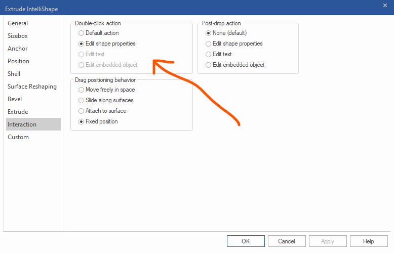
Yes it would be good if this area received some more development You could tie the double click to a range of features, edit cross section , smartpaint, materials, triball , parameter etc.
-
Gimbal Lock issue with 3DConnexion Space Pilot
Nickul replied to RobH2's topic in General Discussion
Hi rob, yes this has been a long standing issue, with my spacepilots, spacexplorers, spacenavigators...... and as you say yes the temporary fix is to fit scene. -
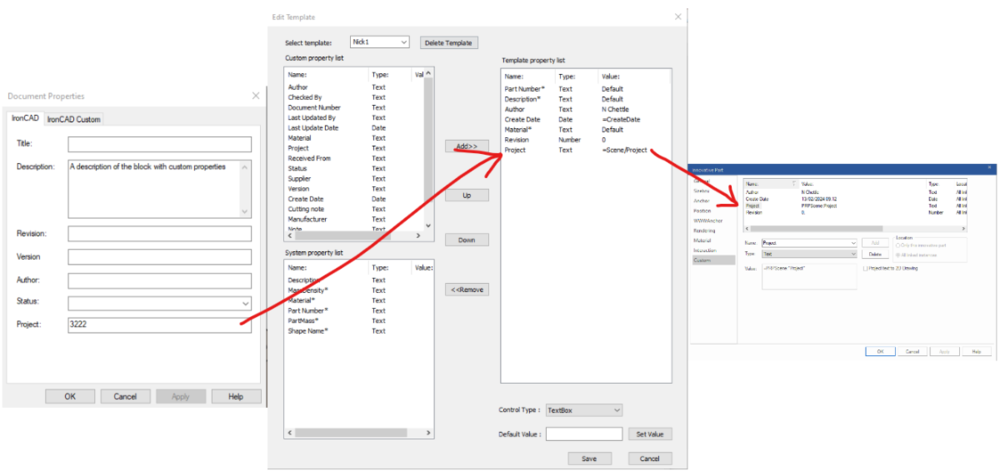
Does anybody know the syntax (or if its possible) to reference the Scene File Properties in the scene? The method to refer to the scene file properties in the ICD is well documentated, i.e. , $PRPView:"IC-Project" , having associated a text box with that view or used a textbox with leader for example. What I want to do, is use the Scene File Properties \ Project field , and drive that into the custom properties of a part. Then taking it a step further, I can then use this within the "Default Property Setting" setup a template for all new parts derive their project field from the Scene File Properties. (I don't want to just set a project number within the Default Property setting as I work across multiple project numbers and I forget to change it, its needs to be saved with the scene). thanks Nick
-
There is also the Statistic's Report. Click on a part , Tools , Inpection sub menu (on the ribbon) , and click Statistics. This will produce a report on any problems with a part, that might be leading to a crash.
-
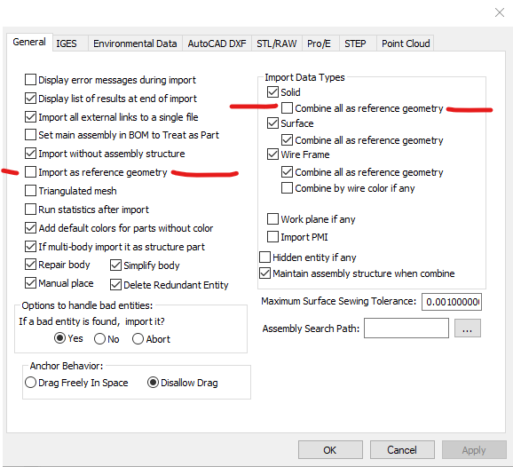
You can create a new catalogue, and drag intellishapes into to this, one or many at once. You can then drag back out (using the existing part for placement) to make a new part. Granted though if you have 75 intellishapes thats quite a bit of dragging in and out..... I use this technique to copy intellishapes from one part to another. Export as Step and importing breaks them up into individual parts. But obviously you loose the intellishapes to BREPs, no great loss if your comfortable with the direct shape modelling features. Make sure none of the "combine as ref geo" are checked otherwise it will smarge them together. (in import options)
-
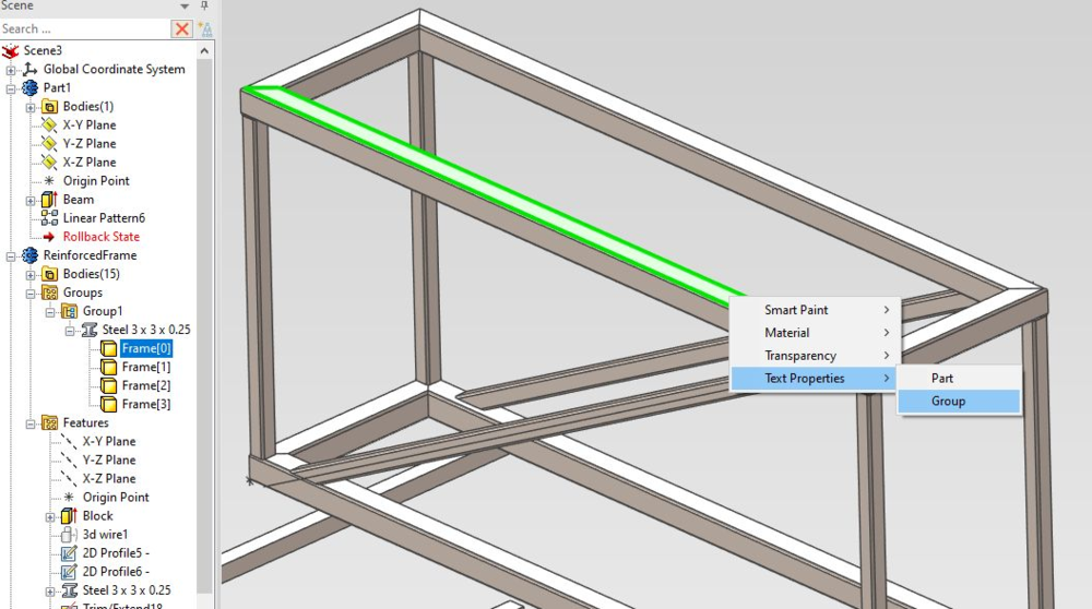
I'm a fan of the eyedropper. Suck up the properties of a part and then when applying , right click , you get additional options, one of which is to apply the text properties to a group. Therefore prior to this grab several of the Frame members, for your structured part frame, and group them. You can then apply the text properties to the group. And drum roll ..... , it doesn't work.... So perhaps related to the ER Malcolm is refering to when dragging in text properties from the catalogue.
-
this has caught me out recently, =Shape1\Sizebox\Width & " x " & Shape1\Sizebox\Length & “ x ” & Shape3\Shelling\ShellingThickness & " Box" =Shape1\Sizebox\Width & " x " & Shape1\Sizebox\Length & " x " & Shape3\Shelling\ShellingThickness & " Box" look carefully at the two strings. I was constructing these in Word (bad idea) and the quotation marks for the second x are the wrong character, they must be a different ASCII code. Its very subtle on this font here, in Word its more pronouced, but they are "stylised". IronCAD does not recognise these. Solution was to just filter it through notepad to change the quotes to the basic ones. Is there a way to access the "Individual Face Thickness" under the shelling thickness ? , I've tried Shape3\Shelling\ShellingThickness1 etc.
-
Request: Reordering of Design Variations
Nickul replied to Malcolm Crowe's topic in General Discussion
Has there been a resolution to this ? I've just tried with 2023 and I'm unable to drag the tabs around. What would also be good if you could export the Design Variation table information to excel and also re-import it. Then you'd have all the power of excel in creating new variations with their dimensions. -
aha , brilliant that's it thanks Cary.
-
Hi, I'm using the dynamic part naming quite a bit now. is there a way to reference the shell thickness. I get I could do this by creating a parameter and then linking the shell thickness to this and then referencing this parameter in the part name but can you do it natively? i.e. just by typing =Shape2\ShellFeature\Thickness into the description field I've had a look through the API docs to see whether I could spot any clues but to no avail I want to reference the size of box section, i.e. I'm after "50x50x3 Box" and then I can list the length of the section in a separate column in my BOM.
-
I've done a parametric weld neck flange driven from excel and using parameters, if you want to have a look and glean any further insights. its on GrabCAD; https://grabcad.com/library/parametric-weld-neck-flange-1 Nick
-
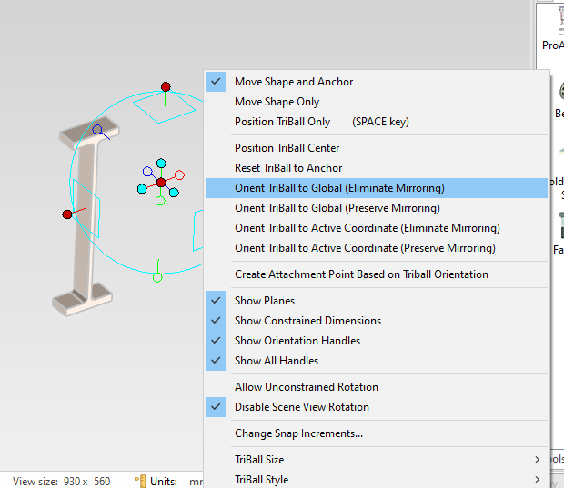
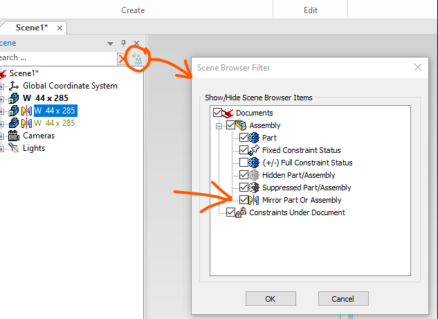
You can still apply a mirror transform onto a part, as your video shows, and the icon shows that, right click on the triball, and it shows the following menu with a mirror transform having been applied to a standalone part. You can switch off the mirror transform icon in the following menu,
-
what your describing and what your image shows conflicts slightly. The tree image your showing is saying they are linked and hence showing the mirror transform symbol. I think this is a good thing as a mirrored part is different, this can catch you out. Can you control the displayed symbols with the following;

-
Selection Filter - Why is Faces by Intellishape Listed?
Nickul replied to Malcolm Crowe's topic in General Discussion
I disagree, the selecting by "Faces by intelishape" can be quite handy sometimes, it enables one click to select all the faces I'm after and a right click , "create - Extract Surface" and I'm away. Can't say I use Faces to intellishape that much, if at all, I tend to use the Sew and solidify in the surface menu. Nick -
Make sure all your parts are in one assembly. Go to the catalogue and right click and drag in a hole block onto one of your parts. Having right clicked you now get the option to drop on an assembly feature. Choose this and then choose "All assemblies/part under selected level". It will now apply this hole block to all of your parts. (it may only interact with one, but if you were to stretch it out it would cut all of them) Go into your sketch, and then copy to clipboard all of your profiles - come out of the sketch. Drill down into the assembly feature hole block (you will have noticed an "AF Group" created in the tree, expand this and there should be a H Block, right click and edit cross section of this H Block - paste in the 2d section you just copied Nick
-
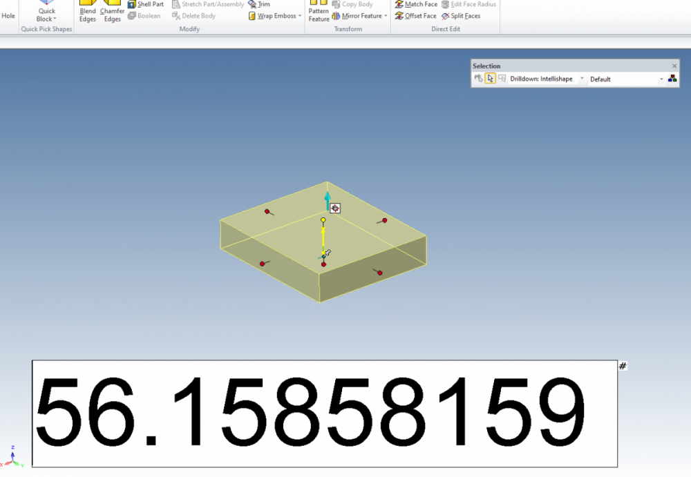
just playing with the dimension font size, increasing it up to 200 (!) makes the text box so big its completely out of the way, see image. As noted though it changes the size of other dimension etc. (Don't forget you can double click the handles this brings up a floating dimension text box, I find this easier.)
-
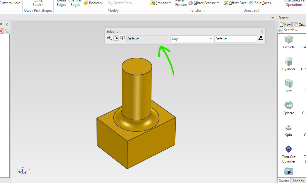
What's this drop down combo box for, on the selection toolbar? Hover the cursor over it and the status text says "Advanced Shape Selector" , it does not seem to ungrey itself and become usable in any of the tools, Nick

-
Nice ! , I didn't realise you could use the eye dropper into a catalogue.
-
Yep, been using my spacemouse plus for 15 years now, I could not be without it. I have slaved the S key to the right hand button so i can quickly bring up the menus and the "1" button is the triball, 2 unlocks the triball etc... Occasionaly the zoom goes a bit mad, but "fit Scene" fixes it. Nick
-
sometimes my spacemouse movement goes a bit mad, to fix it I click the fit scene button on the bottom toolbar.
-
Will, Not especially, I would wager it had something to do with my graphics. I'm using OpenGL2. Try having a play with geometry thickness within the 2d section, (while in the 2d section , right click and choose the show option. in there change the geometry thickness number, its quite insensitive, i.e. a number of 0.1 gave me quite thin lines, and a number of 100 gives me lines almost appear '20mm' wide, see image below;
-
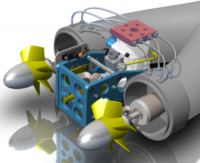
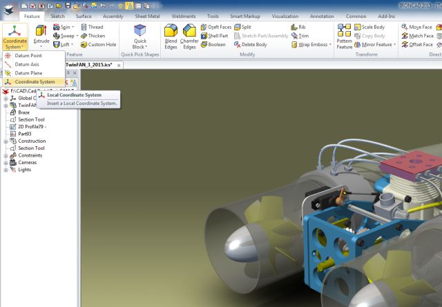
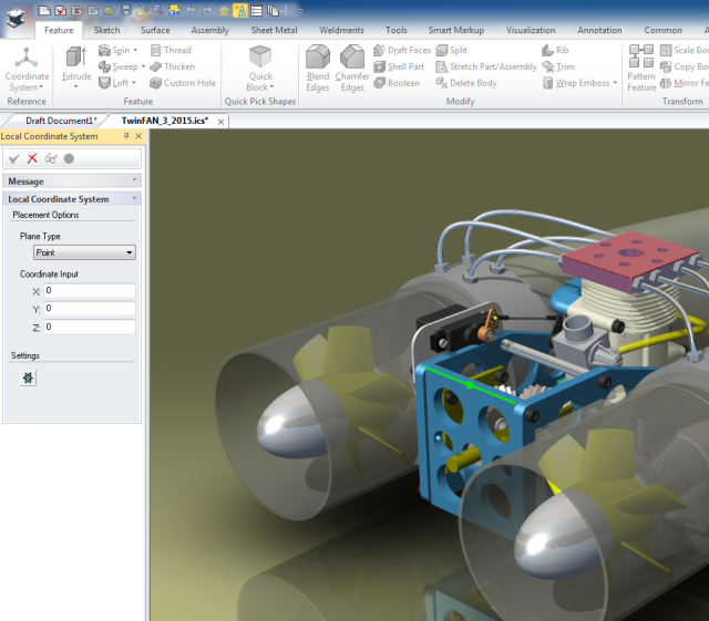
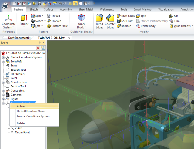
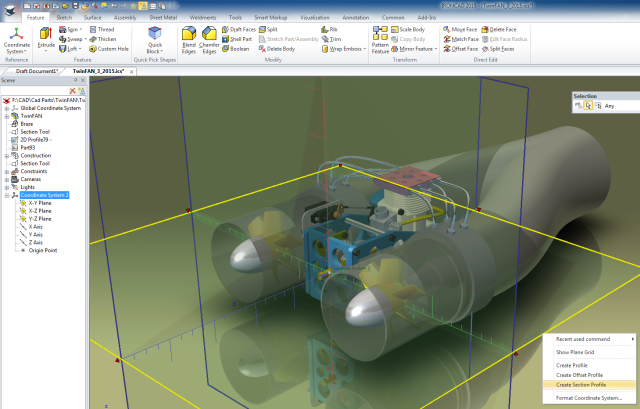
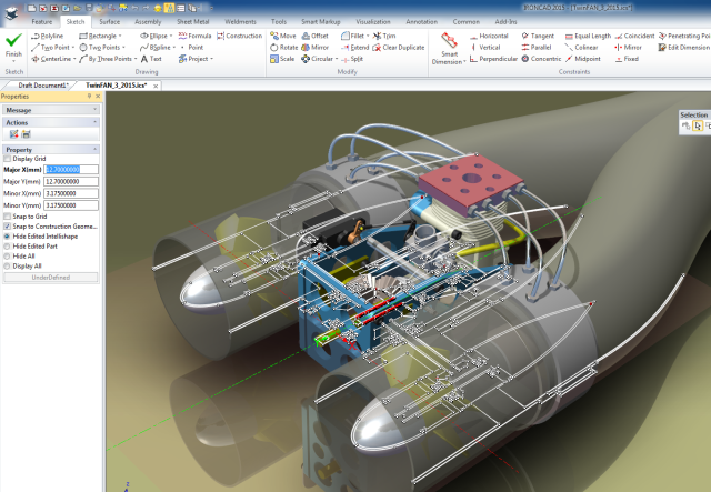
Hi Harley, I've not really sorted out the video thing yet, here are some steps and screen grabs showing the process, (incidentally what software do you guys use to capture video?) Step 1 - On the feature menu create a new co-ordinate system Step 2 - Place this co-ordinate system, from the image I'm placing on the top edge of the front frame, click the green tick to accept the command Step 3 - Right click the newly created Co-ordinate system in the scene and make active. With it selected turn on the triball and position as desired Step 4 - Select one of the planes in the scene and right click, Choose "Create section Profile" Step 5 - Edit the this newly created profile as per usual. Notice that the plane only extended half way along the downstream region of the duct, in Step 4, and in Step 5 the extents of the profile reflects this. Humbug, in trying to clear and reduce my attachments I now cannot reload the images back up.... Nope it really will not let me upload any images now.... I've done a Grabcad tutorial with the images and steps, see this link; https://grabcad.com/tutorials/using-the-co-ordinate-system-to-create-a-section
-
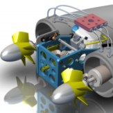
Will, You can also use a co- ordinate system to section a model. Under the feature menu, create a new co-ordinate system and position one of the planes on your desired section. Right click the plane and choose, Create Section Profile. This creates a 2d sketch section, it does not cut the model, which I understand you are asking about but this is sometimes an advantage. By changing the size of the plane also controls the section extents, i.e. you can just section a small region of an assembly. By opening the sketch with it displayed on-top of the 3d model may reveal issues. The other advantage of this method is you can copy using the triball, 20 or so planes 50mm apart and quickly create multiple sections without having to wait for the parts to regenerate. Nick