Leaderboard


Popular Content
Showing content with the highest reputation since 05/09/2023 in all areas
-
Recently I needed to create some 3D models from PDFs received from a client. These PDFs didn't include all of the dimensional information needed, so I was grateful to have at my disposal the "PDF Import" tool within CAXA (not to be confused with the "Insert PDF Underlay" tool). The "PDF Import" tool converts PDFs into CAD geometry (which is what I needed). Attached is a video demonstrating how this works. The PDF used in the video was originally created in CAXA, and the original "Layers" from the CAXA drawing were saved within the PDF. During "PDF Import" these same layers are again imported back into CAXA. Depending on what print driver (or software) created the PDF, "Layer" information may not be available. Malcolm CAXA - PDF Import.mp46 points
-
Regarding question 2. Attached is a video demonstrating how to provide "Control" over the position of the Vertical Frame Members. This method uses 2D Sketches, where the position of the Vertical Lines (Paths) can be controlled independently using Sketch Shape Handles (and unlocked dimensions). If the Sketch Dimensions are "Locked", these positions can also be controlled using Parameter expressions, so that they follow any size changes made to the top and bottom Frame Members. Also attached is a video demonstrating what Cary is suggesting, regarding adding vertical 3D Curves for these Vertical Members. This is a good solution if you always want these Vertical Members locked to the referenced geometry of the Top and Bottom Members. Malcolm STRUCTURED FRAME - Positioning Vertical Members with 3D Curves.mp4 STRUCTURED FRAME - Positioning Vertical Members with 2D Sketches.mp45 points
-
Hi Kim, IRONCAD (CAXA) 2024 introduced the capability to have multiple "Papers" within a single tab. This was introduced specifically with the "Model" tab in mind (like the example in your image), but it is also applicable to the "Layout" tabs as well. Attached is a video demonstrating the principle of how this works. Regarding what file format to use in CAXA, we normally use CAXA's *.exb file format. We only save as *.dwg when we need to collaborate with other CAD software (like BRICSCAD that we also use). This might not be 100% correct, but I've noticed that when *.dwg files are used (instead of *.exb), then the dimensions applied to Generated Views within CAXA are not associative. That is, if the 3D Model changes and the Generated View updates, then the dimensions in CAXA don't follow as they do for *.exb files. It's more efficient to annotate drawings of IRONCAD Scenes within CAXA (with full access to 3D properties as well), rather than externally referencing into other software for this purpose. However, when you need to incorporate associated Generated Views from CAXA within 2D Models of other CAD software (like AUTOCAD, BRICSCAD, MICROSTATION, etc.) then externally referencing *.dwg files from CAXA is a good option to have. Malcolm CAXA - Multiple Papers within Model Space.mp44 points
-
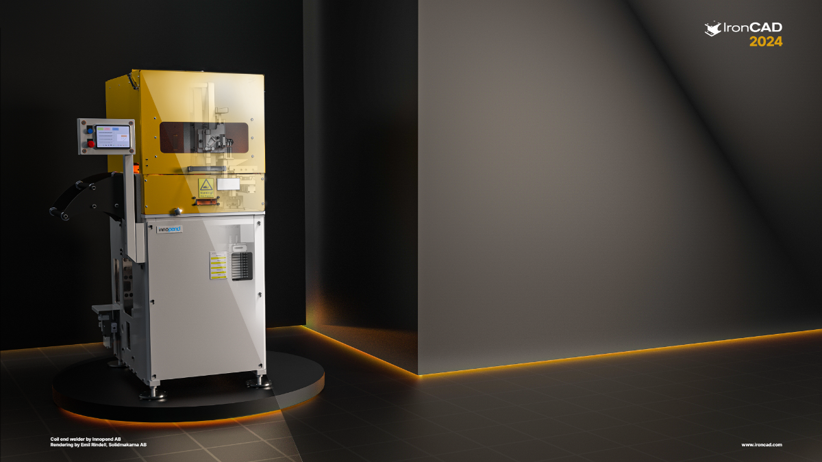
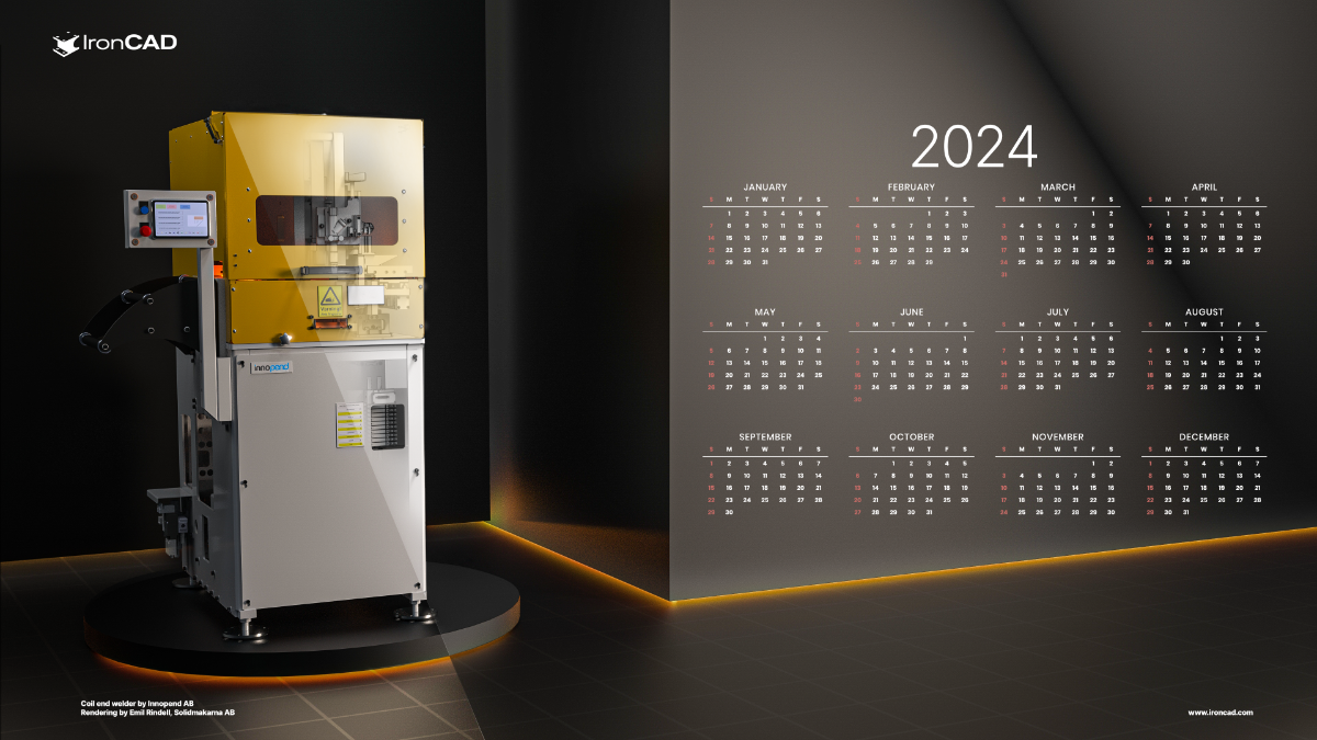
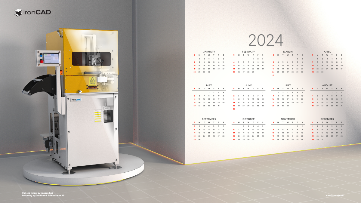
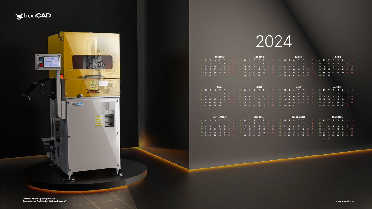
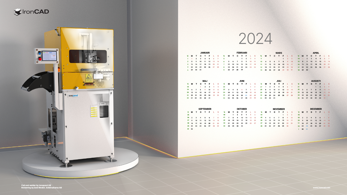
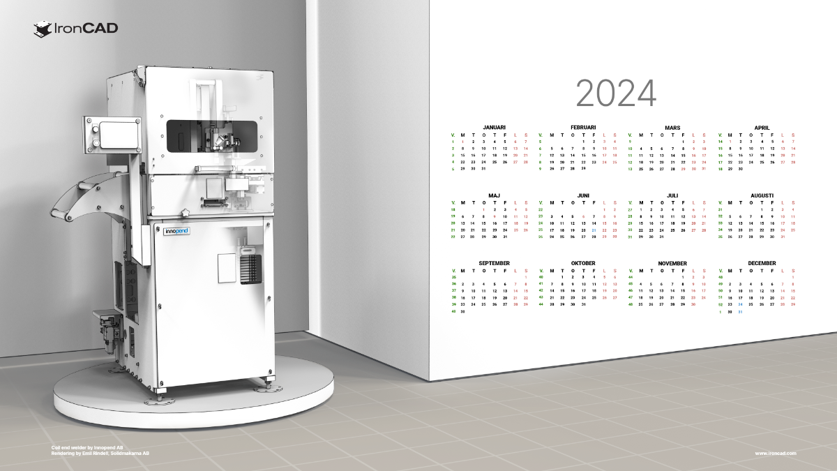
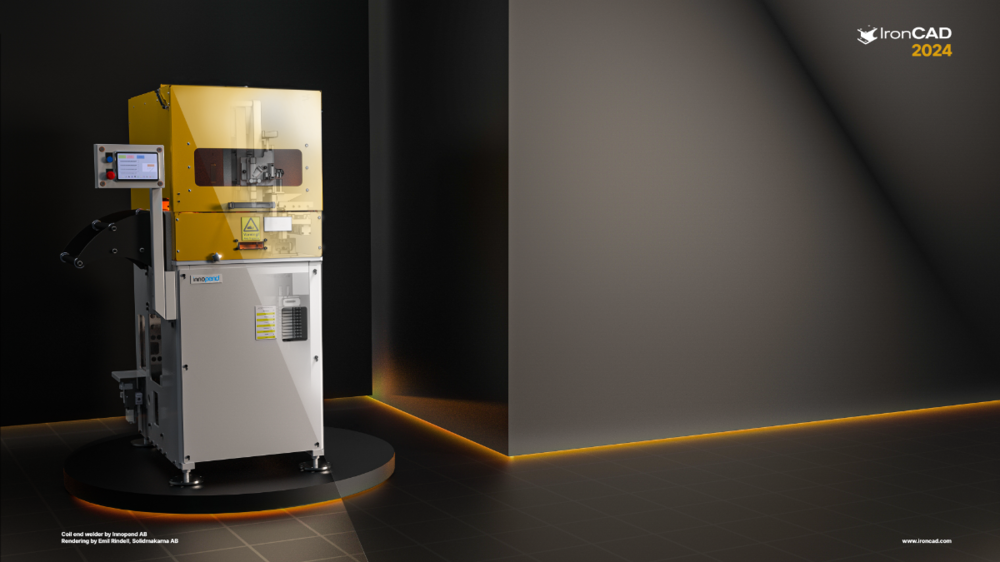
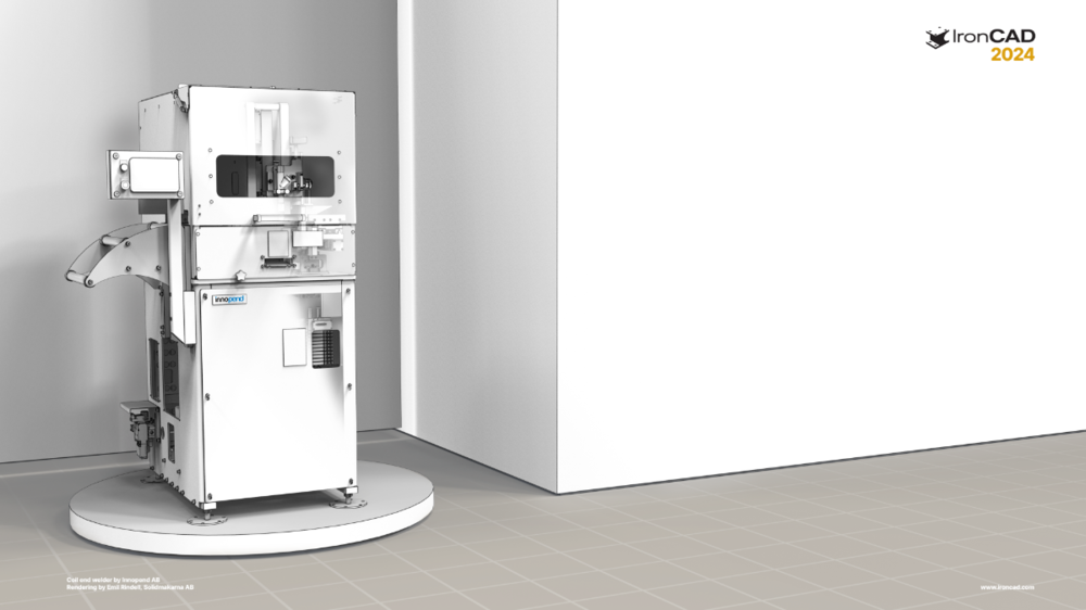
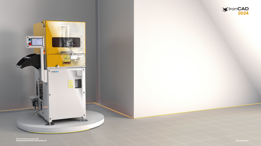
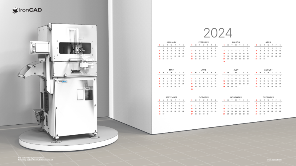
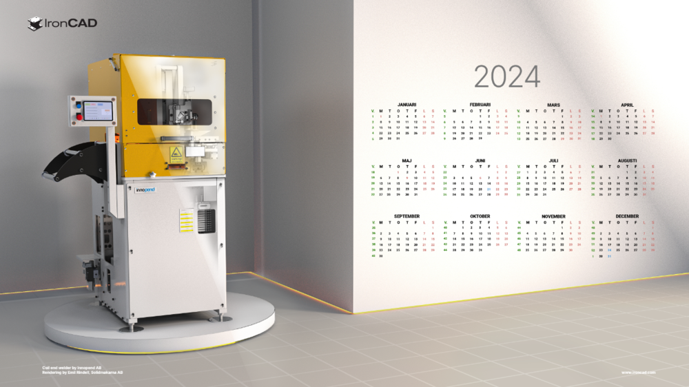
Hi all, Like the past years I decided to make some wallpapers with v2024. Model is a Coil End Welder constructed by the IRONCAD user Lennart Freidlitz at Innopend Teknikpartner AB. Hope you like it! Happy holidays IC_2024_BLACK_4k.png (10,8 mb) IC_2024_CAD_4k.png (3,5 mb) IC_2024_WHITE_4k.png (12,1 mb) English Calender Black (11,3 mb) English Calender White (10,6 mb) English Calender (3,8 mb) Swedish Calender Black (11,0 mb) Swedish Calender White (12,2 mb) Swedish Calender (3,8 mb)


 4 points
 -
Hi tgjang, I just used that old example because I knew it had many Sectioning Configurations already setup in it; but I don't consider that model to be complex compared to other work we do. For that particular project we needed to create a 3D model of an existing Multi-Storey Building (over 100 years old), so that we could then add various new Structural Elements for Earthquake Strengthening purposes. So, it doesn't include all of the details (such as steel reinforcement and connection details) that would have been needed for constructing the original building. We only needed to add details for what was to be added for strengthening. If you're curious regarding the types of structural drawings produced in CAXA from this 3D model have a look at the attached PDFs. Malcolm W140507c-S11-S19-BC1 Plan Sections.pdf W140507c-S21-S32-BC1 Southern Sections.pdf W140507c-S41-S44-BC1 Western Sections.pdf W140507c-S51-S60-BC1 Strengthening Details and Pile Cap.pdf4 points
-
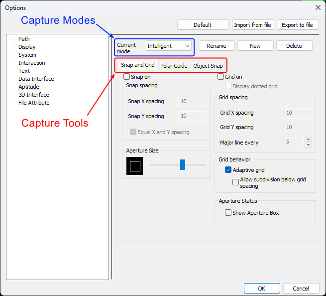
CAXA provides some really helpful tools to assist with selecting and creating geometry. The attached video and document provide an overview of these "Capture Tools" along with the associated "Capture Modes". When editing "Capture Tool" options it's important to be aware that these changes are only applied to the currently selected "Capture Mode". Malcolm CAXA - Capture Tools and Modes.mp4 IRONCAD DRAFT - Options - Aptitude (Capture Modes) - 20230905.pdf
 4 points
 -
This video specifically relates to the "Parallel Capture Tool". This is enabled when using the "Guide Capture Mode". Malcolm CAXA - Parallel Capture Tool within Guide Mode.mp44 points
-
Attached is a video demonstrating how to combine 2D geometry (located in a Block) with 3D geometry (located in a Generated View) within "Model Space". And to then display this combined geometry within "Layout Space" at different view scales using "Viewports". This includes how to use the "Align" tool to perfectly position the 3D geometry on top of the 2D geometry, and how to "Pan" (position) the model within the Viewports. This is a good example of when to "Generate Views" within "Model Space" (instead of directly within "Layout Space). Malcolm CAXA - Model Space - Combining 2D and 3D Geometry.mp44 points
-
Because we create a lot of Parametric Parts, we try to be consistent in how we construct and manage Parameter Names (regardless of who is creating the model). The naming conventions that we've used over the years have varied, but for those who are interested attached is our current internal document defining how our Parameter Names are to be constructed. Malcolm IRONCAD - Parameters - Name Construction - 20230708.pdf
 4 points
 -
So to share my experience with IronCad for architecture. The creation process is very nice and fun as we all know. It becomes more tricky when you need the production plans / drawings. So first create your own Styles and Layers! For Line thickness and all hatch. You can save them (IC saves them in the sheet so copy the sheets) and they are ready to use, quite tricky as a start but there is a benefit in the production. PS: Here a nice tutorial would help. So my tricks: 1. Never change the name of the main file, save backups with numbers… So the drawings are always corresponding with the file. (make a backup every day!) 2. in progress the architecture details change all the time …so you must make the same plan many times. Therefore, the ViewManager in IC Mechanical is perfect. With the view Manager you can save any view for each drawing. So you can develop the building and easily update every drawing, no matter which floor or detail. Easily change between the drawings. And then something new for IC: Maurizio of IC Mechanical helps you immediately. If you find a bug or a problem, next day you get an updated software! WOW! Thank you Maurizio! So finally I am relatively happy to make architecture with IC the bugs or ERs in drawing section are known. Hopefully the come. But without the view manager I guess it would be hard. So Mechanical is every doller worth. See the movie! View Manager.wmv4 points
-
If you need a free STEP Viewer for checking the 3D Models exported from IRONCAD, then the OPEN DESIGN ALLIANCE (ODA) recently released their free "Open STEP Viewer". This works in a very similar way to their "Open IFC Viewer" (for viewing BIM models). Attached is a video that I created for a client demonstrating some of the functionality within this STEP Viewer. Open STEP Viewer Open IFC Viewer Malcolm OpenSTEPViewer - Basic Demonstration.mp44 points
-
For users needing "Annotative Blocks" that scale with the "Paper Scale", there are 3 types of “Annotative Blocks” in CAXA DRAFT. 1. Drawing Frames 2. Title Blocks 3. Paratables The name “Paratable” is a bit unfortunate, as this tool doesn’t need to be limited to Tables. It can in fact be used for creating any type of “Annotative Block” (consisting of attributes, line elements, text, etc), that needs to scale with the “Paper Scale”. Attached is our in-house document regarding "Paratables", along with a demonstration video. Malcolm CAXA - Paratables (Annotatibe Blocks).mp4 IRONCAD DRAFT - Paratables (Annotative Blocks) - 20230522.pdf4 points
-
NOTE! The earlier video I made, had a major mistake. This has now been corrected ( noted May 22 20:24 GMT ) Here is a tip for those of you wanting to know which bend is affected when making closed reliefs. NOTE! The text 'Left' and 'Right' is only shown here to demonstrate which side is affected. Obviously you'd never put these texts on your actual model, In addition, Malcolm has kindly lent me his handy ICS file which shows bend directions and 'look-at faces' to share with you. Sheet metal bend reliefs left or right.mp4 Sheet metal bend reliefs left or right part 2.mp4 Sheet Metal - Bend Corner Reliefs - Look At Face - 20230522.ics
 4 points
 -
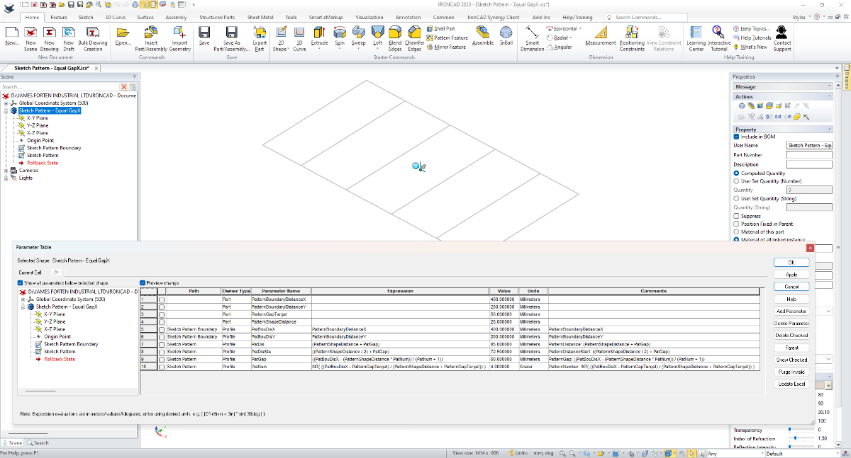
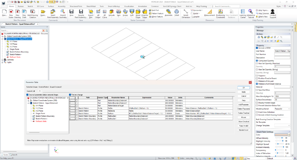
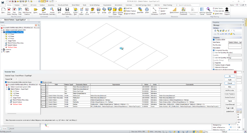
Many users will be familiar with creating "Patterns" using the TriBall or perhaps the "Pattern Feature" tool. But another option is using "Sketch Patterns" within 2D Sketches. This is especially useful when used with the "Structured Frame" tool. Attached are a couple of videos demonstrating what's possible. One example uses Parameter Expressions to calculate an "Equal Distance" between Patterned Objects. Whereas the other example uses Parameter Expressions to calculate an "Equal Gap" between Patterned Objects. Malcolm Structured Frames - Sketch Pattern - Equal DistanceX.mp4 Structured Frames - Sketch Pattern - Equal GapX.mp44 points
-
For those interested, I've attached documents that show the "Custom Settings" that we use within IRONCAD and CAXA DRAFT (specific to 2023 PU1). These "Custom Settings" have a red border around them to identify them as being different from the "Default" setting. The reason for sharing these, is that the "Default" settings aren't going to be optimal for every user. As a result, many users won't be as productive as they could be. Our "Custom" settings aren't going to suite everyone either, but they might be helpful as a comparative guide. Malcolm IRONCAD DRAFT - Options - Custom Settings - 20230905.pdf IRONCAD - Options - Custom Settings - 20231012.pdf3 points
-
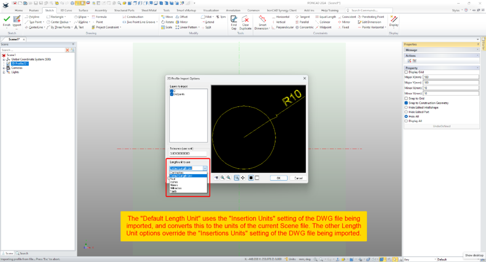
Within 2D Profiles (sketches) it's possible to import geometry from existing DWG files. Within the Import Options Dialog there is the ability to set the "Length Unit to Use". This selection relates to the source file (not the current Scene) and influences the size of the imported geometry. When the "Default Length Unit" is selected, IRONCAD uses the "Insertion Units" setting of the DWG file being imported; and converts this to the units of the current Scene file. If geometry in the DWG file has a length of 10 inches (that is, 10 units set to inches using the "Insertion Units" setting), then IRONCAD will convert the 10 inches into 254 mm (if the Scene units are set to mm). So, it helps being aware of the INSUNITS setting in DWG files. When the other Length Unit options (Centimeters, Feet, Inches, Meters, Millimeters, Yards) are selected, these override the "Insertion Units" setting of the DWG file being imported. So, if the original DWG has geometry with a length of 10 inches, but within the import options the "Length Unit" is set to millimeters, then IRONCAD will treat those original 10 inches as 10 mm instead. This is demonstrated in the attached video, where DWG files using different "Insertion Units" settings are imported into a 2D Profile (sketch). Malcolm 2D Profile Import Options - Length Unit to Use.mp4 DWG Setting - Insertion Units - Inches.dwg DWG Setting - Insertion Units - Millimeters.dwg DWG Setting - Insertion Units - Unspecified.dwg
 3 points
 -
One of the strengths of DWG Editors (like CAXA, AUTOCAD, BRICSCAD, etc) is the ability to externally reference (XRef) other DWG files, in a similar way that we can externally reference other 3D Scene files within a 3D Scene. This is hugely beneficial when DWG files from multiple users (or engineering disciplines) are combined into a common layout. An example could be the layout of a machine or production line (designed in IRONCAD) that needs to be overlayed with a building layout (and other services). The attached video demonstrates how Generated Views in CAXA can be saved as a DWG file, that can then be externally referenced (XRef) into other DWG files, within another DWG Editor (in this case BRICSCAD). When the 3D Scene changes, the CAXA file needs to be opened so that it can be updated and saved. Then within the other DWG Editor the externally referenced CAXA file needs to be "Reloaded" to update the link. The XRef then needs to be "refreshed" by editing a property of the XRef (such as layer, color, etc.), so that any associated dimensions correctly update. Malcolm CAXA - Referencing Generated Views as XRefs within other DWG Editors.mp43 points
-
Hi TaeGyu, The link below is to a new post created with your question in mind. 1. IRONCAD Scene (*.ics) 2. CAXA DRAFT Generated Views (*.dwg) 3. DWG Editor (BRICSCAD) externally referencing the Generated Views from the CAXA drawing. But why not just create the fully annotated drawing in CAXA? This would be more efficient, and you don't lose access to the 3D property information needed for BOMs. Externally referencing Generated Views from CAXA DRAFT is really useful if you're combining these within another drawing (like a building layout, etc.). But it is a more complicated workflow if all you are doing is annotating the Generated Views. Malcolm3 points
-
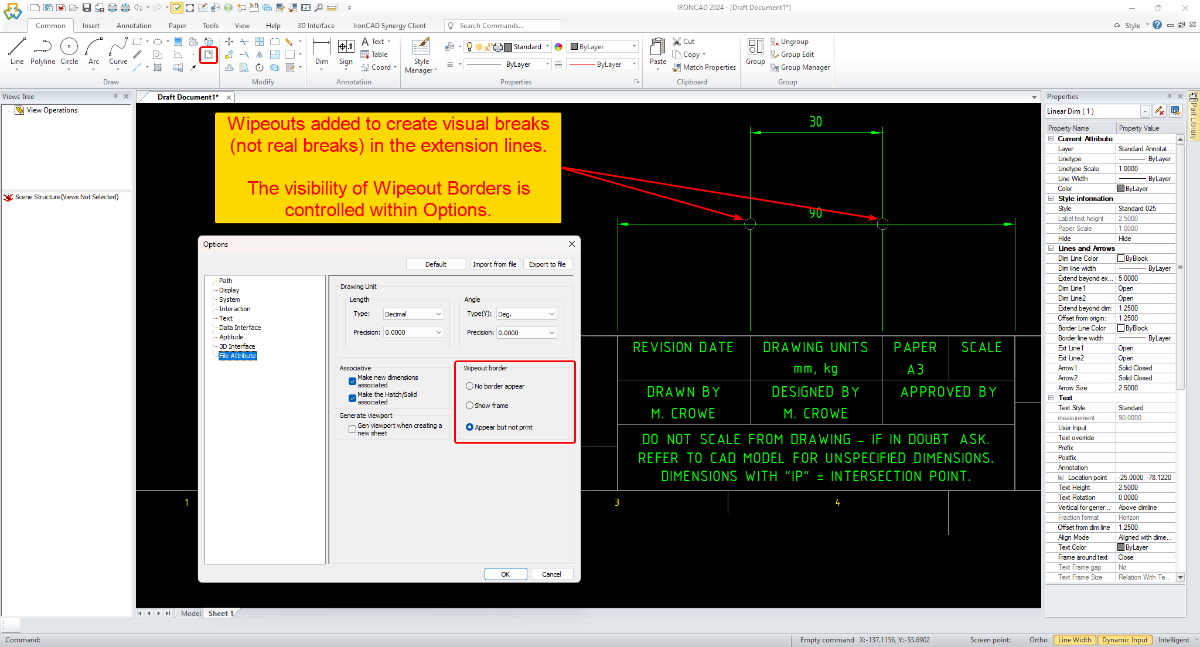
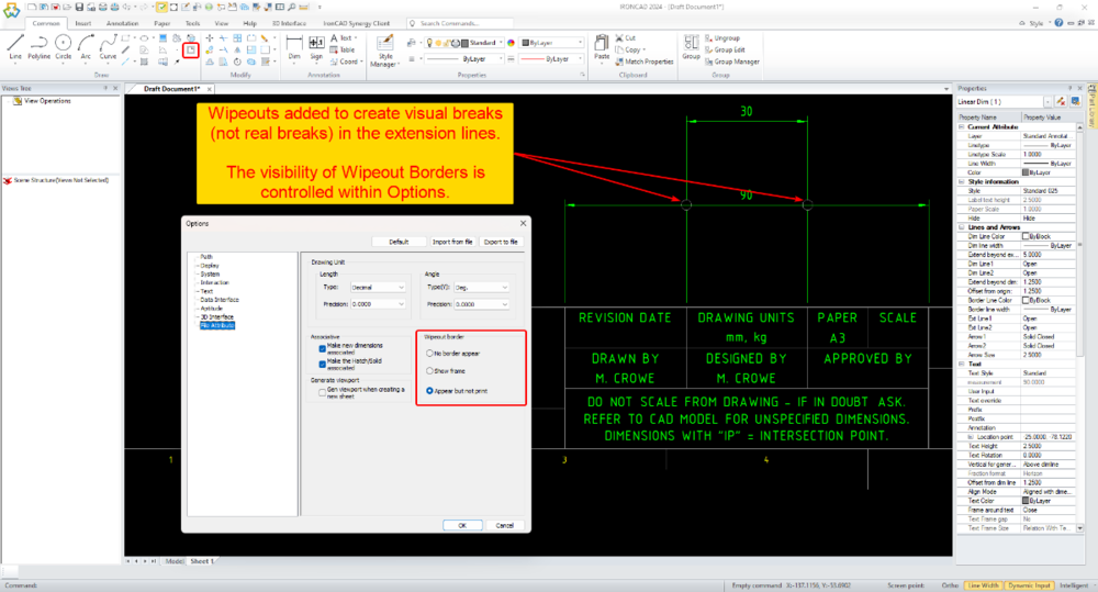
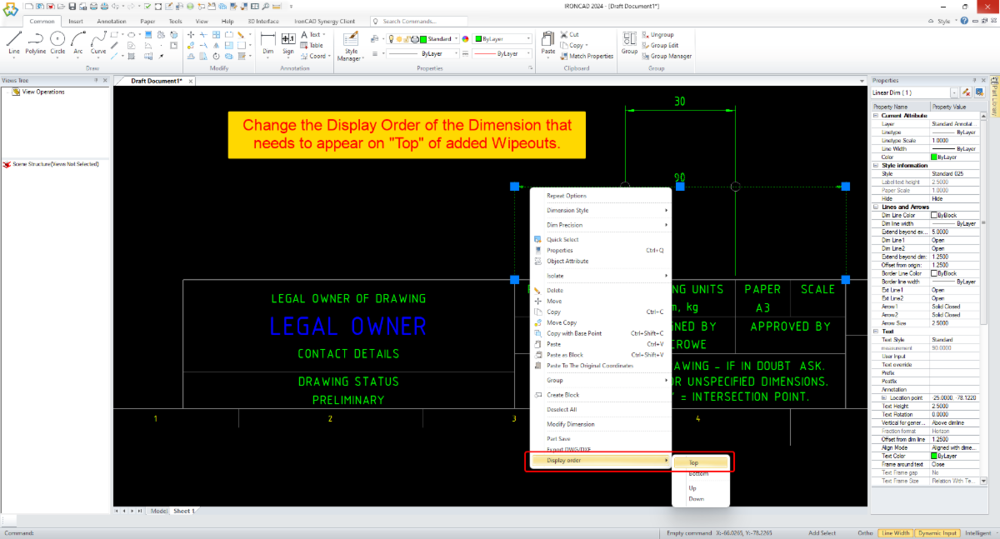
Hi Peter, While there isn't a specific tool in CAXA for this, the attached video demonstrates how to create Visual Breaks in Extension Lines using Wipeouts (to create the same end result). Malcolm CAXA - Using Wipeouts to Add Visual Breaks to Dimension Extension Lines.mp4
 3 points
 -
IronCAD is excited to announce the immediate availability of the IronCAD 2024 Customer Beta #1 to our customers. IronCAD 2024 continues to deliver to the following key areas: Improve Key Functionality that Sets IronCAD Apart from Competition in Target Industries Continue to focus on Large Assembly Performance User Interface and Ease of use improvements Customer Specific Focused Functionality Continued Quality Improvements and Stronger QA Continue to Implement Cutting Edge Technology You can find more details about these areas and the new functionality in the 2024 release in the video presentation in the link for the IronCAD 2024 Download. https://community.ironcad.com/index.php?/forum/238-ironcad-2024-customer-beta-forum/3 points
-
This is an example of how to combine multiple Imported Parts (whether Innovative or Structured) into a single Part using the "Copy Body" tool. Malcolm Copy Body - Combining Multiple Parts into One.mp43 points
-
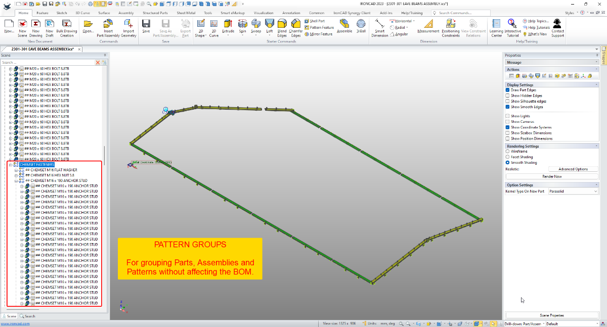
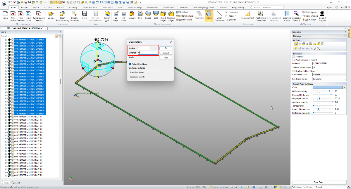
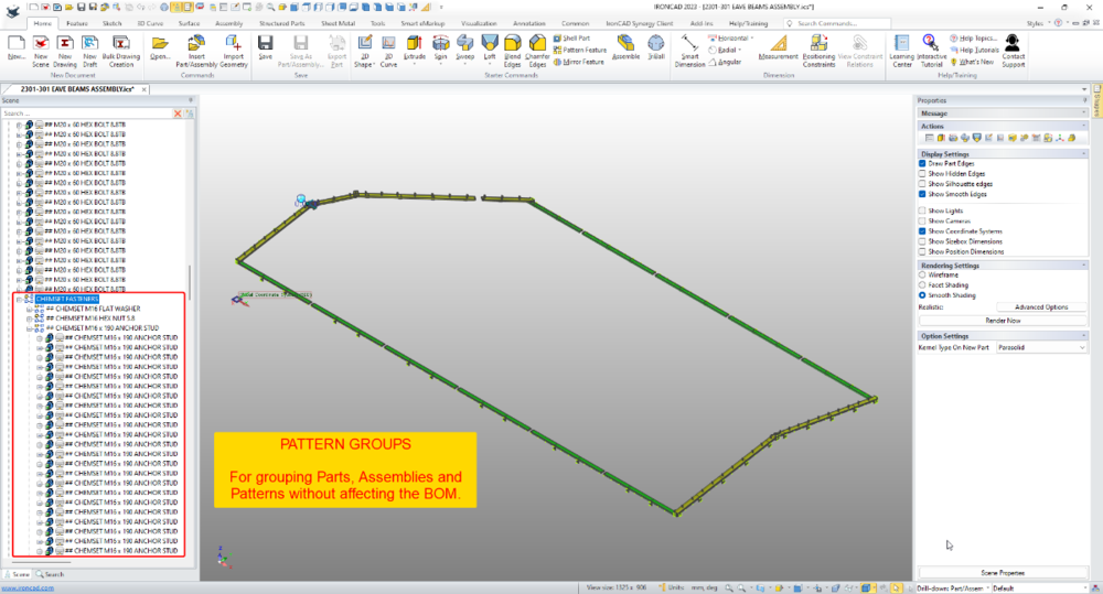
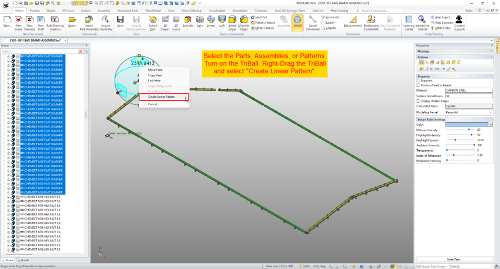
I use the term "Pattern Group" as a Group (of Parts, Assemblies or Patterns) created using the "Linear Pattern" tool of the TriBall; where the pattern number has been set to "1" and the distance to "0" (zero). "Pattern Groups" are extremely useful for simplifying the assembly structure within the Scene Browser, without affecting the BOM (which would be affected if an Assembly was used). The attached video demonstrates how this can be used for grouping hundreds of fasteners to greatly simplify the assembly structure, without affecting the BOM in the associated 2D Drawing. It also includes placing Pattern Groups within other Pattern Groups. Malcolm IRONCAD - Pattern Groups - Alternative to Assemblies and Groups.mp4
 3 points
 -
After a couple of frustrating moments of having no bend lines and annotations show up on a CAXA drawing unfold and hearing from Malcolm as well about a problem regarding centre lines not showing up, there's a simple fix that some people may not know. This is caused by the ICS model not being perfectly lined up in the scene. Even just .01 degrees out in one plane, once the unfold takes place the bend lines and annotations will not appear. Similarly as Malcolm related to me, even centre lines won't show up if the model is out of line in the scene. So if you experience this problem, then check your scene for the part alignment and your unfold for the same. Setting front view definition also helps. Harley3 points
-
Hi tgjang. In the attached video I demonstrate the 3 methods that I'm aware of. 1. Stretch Handles (Triangle): Note the settings within "Options" regarding Relative and Absolute. Also ensure that "Dynamic Input" (bottom right) is turned off. 2. Stretch Command: Use the "Single Select" option in the bottom left corner. 3. Dimension Drive: Temporarily enables you to drive geometry using the associated dimensions. Malcolm CAXA - Stretch Handle, Stretch Command, Dimension Drive.mp43 points
-
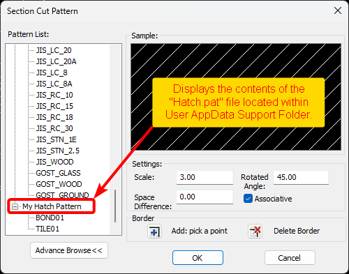
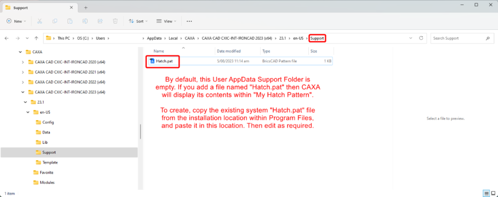
By default, CAXA includes a comprehensive list of Hatch Patterns that are available for both 2D and 3D hatching. However, it's possible to add other Hatch Patterns from other DWG Editors (including AUTOCAD), without the need to create them yourself. This is done by adding a "Hatch.pat" file within your User AppData CAXA Support Folder. Then within this file, either paste the desired contents from other *.pat files, or manually write the Hatch Code (if you understand how to do this). This is demonstrated in the attached video. Malcolm CAXA - Adding Hatch Patterns.mp4
 3 points
 -
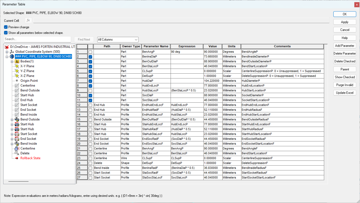
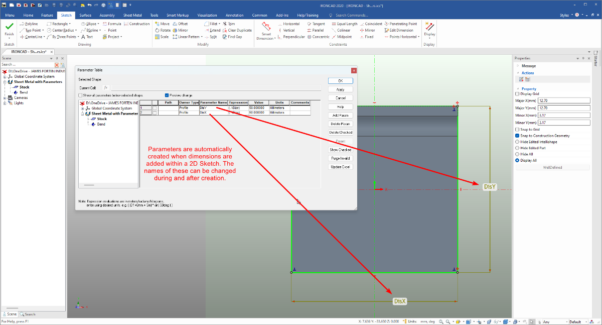
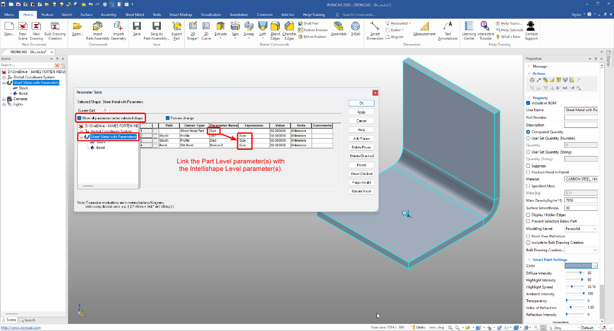
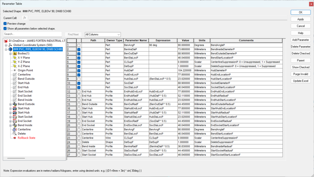
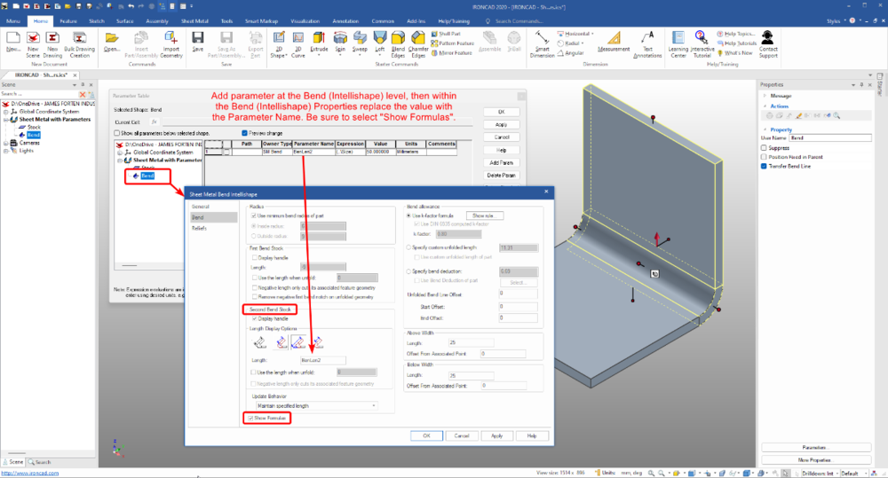
For those wanting to create Parametric Sheet Metal Parts, the attached video demonstrates how to apply these within the 2D Sketch of Stock, and within the Intellishape Properties of Bends. I’ve also attached some images and the 3D file from the demo. This was created specifically for another user (in IC2020), but I thought other users might have a similar interest (or need). Malcolm IRONCAD - Sheet Metal with Parameters.mp4 IRONCAD - Sheet Metal with Parameters.ics

 3 points
 -
Hi James, The link below is to a previous Enhancement Request in 2020 (ticket 114048) regarding dragging-and-dropping Text Properties from a Catalog onto selected Bodies (Frame Members) within a Structured Part. In a separate Enhancement Request in 2022 (ticket 11891), I've also asked that Default Property Templates for Structured Frame Members be added within Options, so that Frame Members can be automatically populated with the desired Custom Properties during creation. Malcolm3 points
-
Dear Iron Cad the Update already saved me time at drawings! -Fix Drawing on paper -Move Text with arrow tabs I am so happy to have it in! Thank you so much!3 points
-
Hi Kim, The "Properties" displayed in the Properties Browser of my Paratable are the "Attributes" that I defined inside my Paratable. If the "Fill in Paratable" dialog is empty (as in your image), this is because there aren't any "Attributes" defined inside the Paratable. In the attached video I create a Paratable using "Text" and a Paratable using "Attributes" to demonstrate the difference. I hope that helps. Malcolm CAXA - Paratables - Attributes vs Text.mp43 points
-
For those interested in understanding how these "Sketch Patterns" and Parameter Expressions work, I've attached the ICS files, along with images of the Parameters. Malcolm Sketch Pattern - Equal DistanceX.ics Sketch Pattern - Equal GapX.ics Structured Frames - Sketch Pattern - Equal DistanceX.ics Structured Frames - Sketch Pattern - Equal GapX.ics
 3 points
 -
(ATLANTA, Ga.) April 25th, 2024 – IronCAD, a leader in CAD solutions for design productivity and collaboration, is excited to announce the first product update of 2024 for its flagship CAD software. IronCAD 2024 Product Update 1 (PU1) brings significant enhancements and product quality improvements across general modeling, sheet metal design, and collaboration capabilities, designed to accelerate the design process and improve user flexibility in a multitude of engineering environments. In addition, IronCAD is excited to announce the launch of the IronCAD AI Chatbot, a revolutionary new feature designed to enhance user experience and proficiency with IronCAD software. This cutting-edge tool, powered by the latest ChatGPT 4 AI system and backed by an extensive IronCAD database, offers users comprehensive guidance, enhanced learning, and new user guidance on IronCAD’s unique design approach. Read More.. Access Product Updates at https://www.ironcad.com/product-update/2024pu1/2 points
-
We have a license of SolidSteel in our company that we can run with SolidWorks. I think you can't compare solidsteel to Structured Frame because foremost one license of Solidsteel (SaaS, five years) costs as much as a perpetual license of IronCad. Then you have to keep in mind that when you are done with your designed structure, you have to press a button called "finalize assembly" which breaks all references and replaces all geometraclly same parts with one. Solidsteel uses special internal references because other way it would not work in the fully parametric world of Solidworks. Solidsteel works only in assemblies. Structured mode is more like weldments in Solidworks. In my opion most bang for your buck you get with using IC Mechanical in Innovative mode combining some elements in structured mode as Malcolm has shown in some posts. Solidsteel is not a bad addon but considering the cost i think you get 80% of the features of it in IC at 20% of the cost. If you design much complex steelwork with weldment preparation and drawings for the individual parts and have a machine or supplier that uses DSTV file format, then Solidsteel might be a choice. Stefan2 points
-
Solidsteel is an addon that was also made for Inventor. Looks like the most advanced structure addon to any cad package that I also noticed. Inventor is very good without the Solidsteel addon. I tried using the Structured Frame also and I think it is half thought out and needs a lot of work. ZW3D is fairly complete with their Structure Module except they only have profiles in metric and it don't look easy to make profiles for Imperial system.2 points
-
TriBall Dimension Creation for Parts.mp42 points
-
Dear Customers, We are thrilled to announce the release of IronCAD 2024 Service Pack 1, which is now available for our valued customers! This service pack fortifies the quality and reliability of our latest milestone release, IronCAD 2024, ensuring an enhanced user experience for you and your customers. In addition to bolstering the core functionalities of IronCAD 2024, we are proud to introduce our new Architectural & Viewing Translator (“A&VTransPlus”). This powerful add-on translator expands import/export capabilities specifically tailored for the architectural engineering construction (AEC) fields, now including Revit* and IFC Read/Write functionalities. A&VTransPlus is an additional licensed translator option that is available for IRONCAD and INOVATE only. Note: Customers do not need to have Native Translator prior to adding A&VTransPlus (It can run independently or alongside Native Translator). Revit Write is currently unsupported (see *Note below). We’ve also included a complimentary feature enhancement: the addition of a GLTF write format to the standard IronCAD product. This means that you can now enjoy enhanced export options without the need for additional translator packages. It’s our way of streamlining customer workflows and boosting efficiency. Please contact your local reseller for details on pricing of the Architectural & Viewing Translator. Architectural & Viewing Translator (“A&VTransPlus”) Details The following are the read/write formats versions for the A&VTransPlus: Revit Read – Version 2015 to 2023. Revit Write – Write is only to Revit 2023. *Note: The current release of Revit Write is unsupported for support until a future release update is announced. IFC Read/Write – IFC2x3, IFC4 For the GLTF Writer added to the standard product, the write version is: GLTF Writer – Version 2.0 For more details about the Quality Improvements and access to the latest downloads, visit https://www.ironcad.com/product-update/2024sp1/. Best Regards, IronCAD Team2 points
-
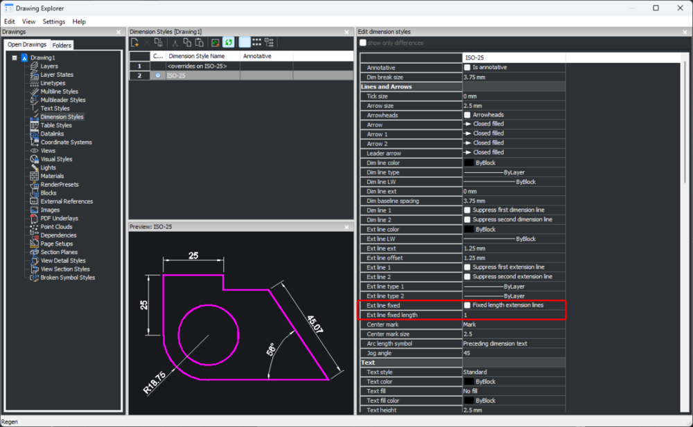
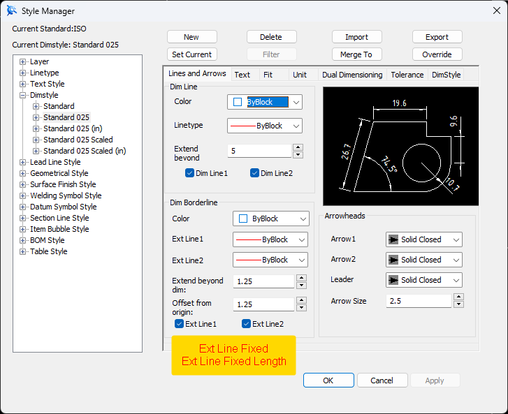
Some DWG Editors (based on the ODA Drawing SDK) include two settings for fixing the length of Dimension Extension Lines, as an alternative to the normal offset from the selected geometry. While CAXA hasn't implemented these two settings (currently), the attached video demonstrates how to achieve the same end result by turning off the generated Extension Lines, and manually adding Fixed Length ones using CAXA Symbols (Library). Malcolm CAXA - Manually Adding Fixed Length Extension Lines.mp4
 2 points
 -
Hello! Just installed on an Apple silicon M3 Macbook with Parallels + Windows 11 and... it works! Had to change graphics driver to OpenGL2 instead of DirectX, but nothing else was needed. (Menu>Options>Rendering>Driver Type) Note: I only just tested this, threw in a few parts to see if it could handle them and all worked fine. But I haven't done sustained work where I assume there might be problems floating around different areas.2 points
-
IC2024 seems to work without hiccup Untitled video - Made with Clipchamp.mp42 points
-
Best wishes to the team and to all community members.2 points
-
If you can ignore the effect on other possible drawings etc, the absolute fastest way must be this! 1) Select the object(s) 2) Drop the ICM Set Include in BOM Status (left mouse button toggles all ON, right mouse button toggles all OFF) http://ironcad.it/learnICM/en/utils-catalog/010_set_include_in_bom_status/2 points
-
Hi Peter, To my knowledge, the Section and Broken-Out Section tools don't work with Isometric Views. To achieve any type of Sectioned Isometric View in CAXA we create the desired section in a specific "Configuration" within the 3D Scene, that we can then select when generating the View. The principle is demonstrated in the attached video. These sections can be created using the "Section" tool, or by using "Assembly Features" (necessary for Broken-Out Sections). Malcolm CAXA - Creating Sectioned Isometric Views.mp42 points
-
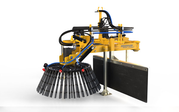 Hydraulically powered weed brush designed in IRONCAD by Broddson and rendered in KeyShot by Emil Rindell Solidmakarna AB.
© Broddson AB and Solidmakarna AB
2 points -
When creating 2D geometry, CAXA will remember the location of the "Last Point" that was placed. This "Last Point" can then be referenced using the "@" symbol, following by Cartesian or Polar Coordinates. The benefit of this is being able to start new geometry at a defined new location relative to the "Last Point", without needing to create any construction geometry. If there is no previous "Last Point", you can create one by starting the Line command, placing the first point, but ending the command without placing the second point. No geometry is created, but CAXA will remember that "Last Point", which can then be referenced using @0,0 (if you want to start geometry at that exact location). In practice, you're likely to start a new point in empty space relative to the "Last Point". For example, using @5,10 (5 units in the X direction, 10 units in the Y direction). This is demonstrated in the attached video, where 2D geometry (weld beads) are being added within Generated Views. Malcolm CAXA - Referencing the Last Point.mp42 points
-
Hi tgjang, Have a look at the attached image and video and let me know if that helps solve your issue. Malcolm EndCut - 20230902.mp4
 2 points
 -
Handle right-click to make a Parameter.mp42 points
-
Hi Sarath, I realise that you were specifically asking regarding ICD, but CAXA has this Weld Bead capability. The attached video starts with demonstrating how to create Stacked Weld Symbols in CAXA, but from around the 1:37 mark, the video then demonstrates the Weld Bead tool in CAXA. Malcolm CAXA - Weld Beads and Stacked Welding Symbols.mp42 points
-
Export to Blender. Use shrinkwrap. Export back to IC. Here is a quick video example of one way to do it using text, but anything can apply here. I use the two softwares together often, especially with 3D printing applications mixing a little cura and other stuff in there. -Spencer Edit: I got it pretty close, but it takes some mesh editing etc. so maybe a bit to take on with a software as user unfriendly as blender unless you are willing to learn quite a bit. 2023-06-12 14-37-50.mp42 points
-
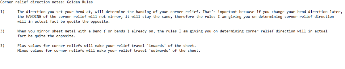
Hi all, Further to my previous videos about working out left or right for corner reliefs, I decided to show you how I go about determining corner relief values on two ( or more ) sheet metal plates requiring internal or external mitred flanges. There are 4 videos, so it pays to look at them in sequence. I'm new at doing videos so take it easy on me won't you 90 degree internal mitred flange.mp4 More on bend reliefs for mitres on separate sheets.ics2 points
-
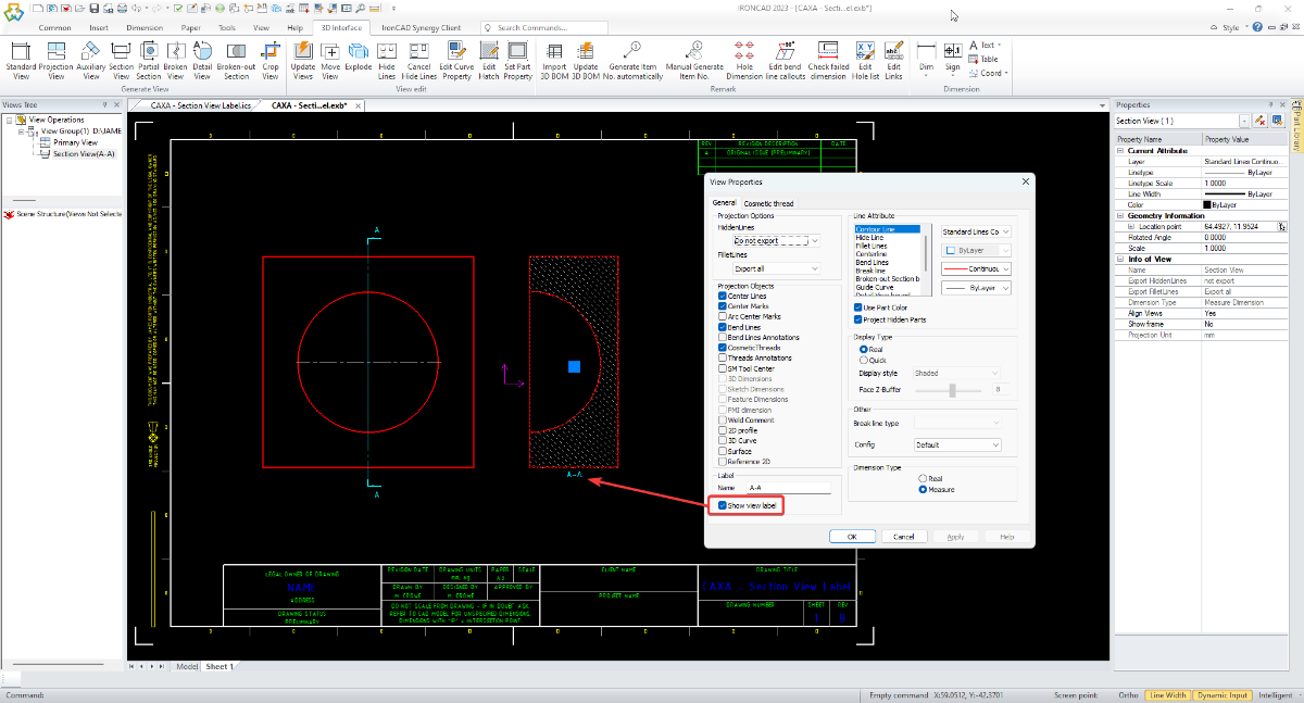
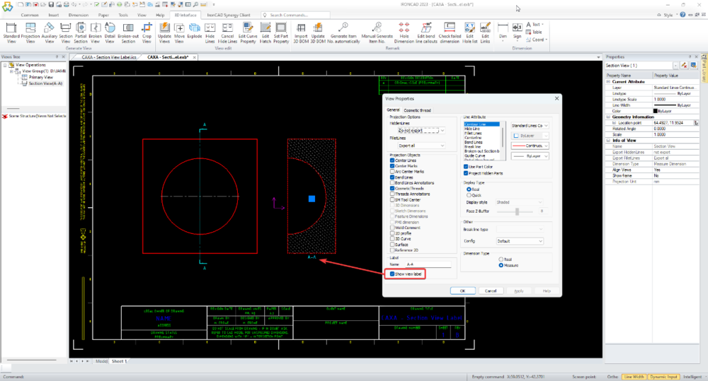
CAXA places its automatically generated View Labels inside the Generated View (which is a type of "Block"). Regarding DWG Editors (like CAXA), any annotations that are placed inside "Standard Blocks" do not scale with the Paper Scale. This is why you're not seeing the View Label change like other annotations do when the Paper Scale changes. Only annotations placed inside special "Annotative Blocks" scale with Paper Scale, and the only "Annotative Blocks" within CAXA are the "Drawing Frames", "Title Blocks", and "Paratables". For CAXA to create the View Label at the correct text height, the "Current Text Style" at the time of generating the View needs to be set to the desired height. One way to do this is to have a "Scaled Text Style" that you can simply toggle on (set as current) when required. Alternatively, you need to double-click on the Generated View to enter into "Block Editing Mode", so that you can then edit the text height of the View Label manually (while inside the Block). Another option is simply to disable the View Label within the View Properties, and to drag-and-drop your own custom View Label into the drawing (which is what we do). Malcolm CAXA - Section View Label - Paper Scale.mp4
 2 points
 -
Hi Kim, You haven't followed the "Tip" video correctly. It is important that the reference files used for the 3D BOM are the same files used for Generating the Views. Try the following: 1. Externally save the Assembly as 4A260 BRACKET LOADING. This is the primary file that the following steps 2 and 3 will be referencing. 2. Start a new scene and insert the Assembly file created above. Save this file as 4A260 BRACKET LOADING - BOM Level 2 (Sub-Assemblies) 3. Start a new scene and insert the Assembly file created in step 1. Save this file as 4A260 BRACKET LOADING - BOM Level 3 (Parts) 4. Within your CAXA drawing, generating views using the new files from steps 2 and 3. 5. Within your CAXA drawing, insert a 3D BOM referencing the file from step 2, and set the Import Level to level 2 (sub-assemblies). 6. Within your CAXA drawing, insert a 3D BOM referencing the file from step 3, and set the Import Level to level 3 (parts). The rest of the details as per the video in the "Tip" forum post. Malcolm2 points
EmilRindell.thumb.jpg.29678b5c5d1acabccc15c66d12b57b42.jpg)