Malcolm Crowe
-
Posts
1,753 -
Joined
-
Last visited
Content Type
Profiles
Forums
Blogs
Downloads
Articles
Gallery
Everything posted by Malcolm Crowe
-

Options - Custom Setting (IRONCAD and CAXA)
Malcolm Crowe replied to Malcolm Crowe's topic in General Discussion
For those interested, attached are our updated custom settings documents for IC2024 PU1. IRONCAD DRAFT - Options - Custom Settings (2024 PU1) - 20240427.pdf IRONCAD - Options - Custom Settings (2024 PU1) - 20240426.pdf -
Hi TaeGyu, There have been positive improvements regarding Structured Frames within recent releases, and there are many potential applications for it; but in my opinion additional enhancements are needed before I'd start showcasing it to users. Perhaps some of those enhancements will arrive in IC2024 PU1 or IC2025 or ....... (I don't know what R&D are working on). In answer to your questions. 1. Sometimes I like to toggle between displaying and exporting Solids and 3D Curves (as part centerlines). This is a huge benefit offered by Structured Frames (and Structured Parts). In these applications I will include 3D Curves, but these are normally "Extracted 3D Curves" from a 2D Sketch. 2D Sketches provide better control and can be driven using parameters. While the 3D Curve tools have been greatly improved recently, they also require additional enhancements to provide the level of control needed. As a result, these aren't my preferred tools. 2. It is very rare that I need to create a Datum Plane (but I'm pleased to have the capability for when I do). You don't need Datum Planes to create 2D Sketches. For example, in your model the Datum Plane wasn't necessary, as the "Sketch Position" tools provide that positioning functionality relative to the XY, XY, and YZ Planes of the Part. 3. For some projects we export the CAXA BOM to Excel Spreadsheets for the reasons that you have listed. All of our BOM Styles contain all of the properties that we might want to display or export. But we control what is displayed in the drawing by controlling the width of the BOM item within the BOM Style. A width of zero (0) means that it doesn't display. Regardless of what is displayed in the BOM on the drawing, when the BOM is exported from CAXA, all of the columns are exported to the Excel Spreadsheet. Malcolm
-
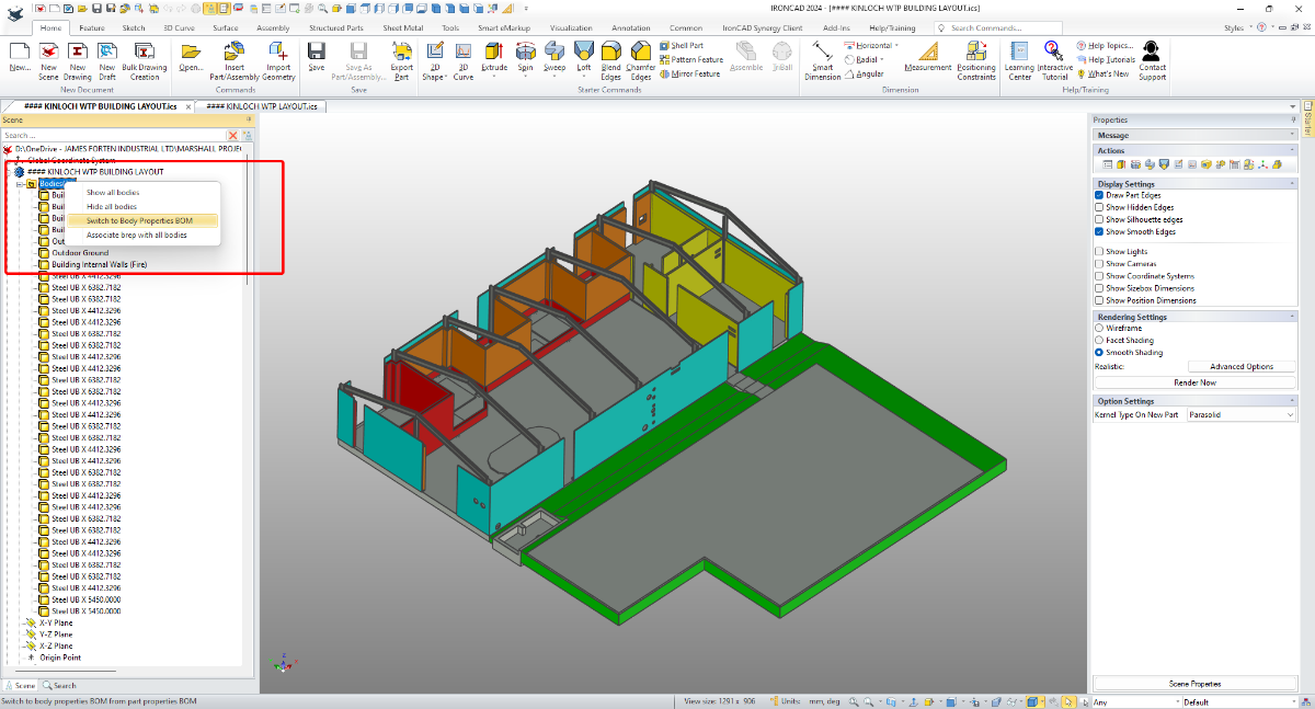
Hi TaeGyu, I'm pleased that it helped. Regarding any Application being written for extracting Part Properties from multi-bodied Structured Parts, it's important to reference the "Switch" between Part and Body Properties. This "Switch" was introduced in IC2024. It you're not familiar with this, see the attached video. Malcolm Switch Between Part and Body Properties BOM.mp4

-
Hi TaeGyu, In the attached video I demonstrate how to apply the requested properties (Description and Material) to the individual Frame Members (Bodies) of the 3D model, so that they then appear in the BOM of your CAXA drawing. I also show how to get the Qty to display and total correctly within the BOM. I hope this points you in the right direction. Malcolm Structured Frames - Bodies in BOM.mp4 STEEL_TEST - MC.exb STEEL_TEST - MC.ics
-
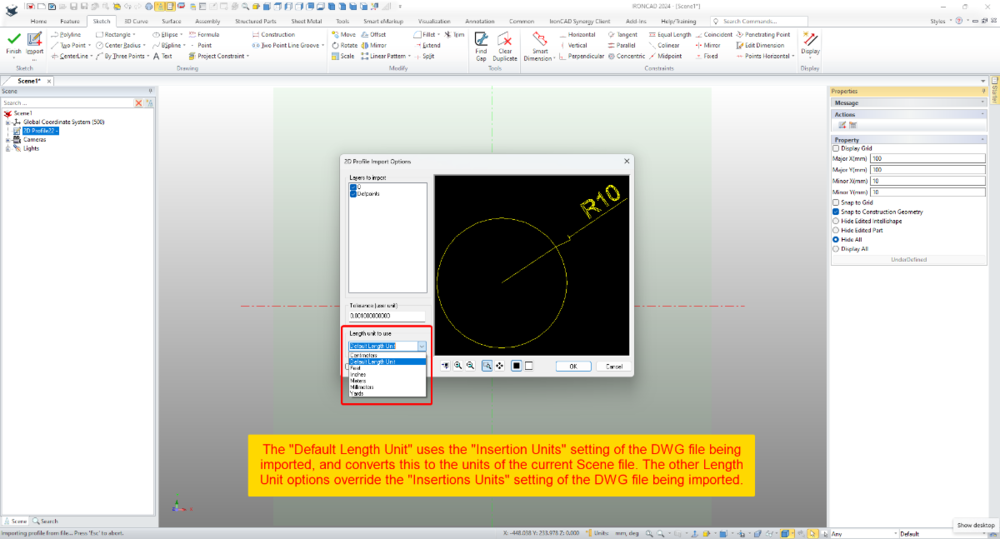
Within 2D Profiles (sketches) it's possible to import geometry from existing DWG files. Within the Import Options Dialog there is the ability to set the "Length Unit to Use". This selection relates to the source file (not the current Scene) and influences the size of the imported geometry. When the "Default Length Unit" is selected, IRONCAD uses the "Insertion Units" setting of the DWG file being imported; and converts this to the units of the current Scene file. If geometry in the DWG file has a length of 10 inches (that is, 10 units set to inches using the "Insertion Units" setting), then IRONCAD will convert the 10 inches into 254 mm (if the Scene units are set to mm). So, it helps being aware of the INSUNITS setting in DWG files. When the other Length Unit options (Centimeters, Feet, Inches, Meters, Millimeters, Yards) are selected, these override the "Insertion Units" setting of the DWG file being imported. So, if the original DWG has geometry with a length of 10 inches, but within the import options the "Length Unit" is set to millimeters, then IRONCAD will treat those original 10 inches as 10 mm instead. This is demonstrated in the attached video, where DWG files using different "Insertion Units" settings are imported into a 2D Profile (sketch). Malcolm 2D Profile Import Options - Length Unit to Use.mp4 DWG Setting - Insertion Units - Inches.dwg DWG Setting - Insertion Units - Millimeters.dwg DWG Setting - Insertion Units - Unspecified.dwg
-
Importing - STP - How to Map Custom Properties?
Malcolm Crowe replied to Malcolm Crowe's topic in General Discussion
Hi Kim, Thanks for your interest in investigating this. Is IRONCAD Support able to comment on these STP importing and exporting questions? Malcolm -
Importing - STP - How to Map Custom Properties?
Malcolm Crowe replied to Malcolm Crowe's topic in General Discussion
Are there any STP experts able to answer these importing and exporting questions? Malcolm -
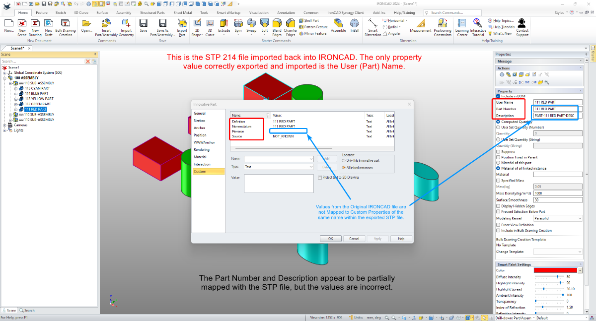
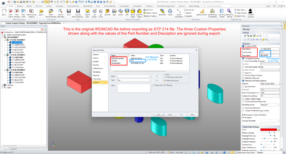
Attached is an image of an IRONCAD file in which I have added three Custom Properties (MaterialDescription, Revision, RevisionDate). Also attached is an image of this file after it has been exported as a STP 214 file and imported back into IRONCAD again. 1. The original Custom Properties are ignored and replaced with others (Definition, Nomenclature, Revision, Source). How can we stop exported STP files from including unwanted Custom Properties, and is there a way to filter what is imported? We currently manually remove these from imported parts and assemblies. 2. How to map the values of the original Custom Properties (Part Number, Description, Revision) to the same Custom Properties in the exported STP file? The exporting process seems to ignore the original Custom Properties all together. Malcolm Custom Property Testing - 100 ASSEMBLY - Exported from IRONCAD.ics Custom Property Testing - 100 ASSEMBLY - Exported from IRONCAD 214.stp

-
Point Clouds (PTS) - How to Set the Import Units?
Malcolm Crowe replied to Malcolm Crowe's topic in General Discussion
Hi Tom, changing the default units of the Scene was the only option that I could find. I tried both mm and m, and it didn't make a difference. Hi Joseph, thanks for the suggestion regarding CloudCompare. Rather than install more software I might try achieving the same result with our other CAD software, since it can both import and export Point Clouds. Ideally though I'd like to be able to adjust the units or scale the Point Cloud in IRONCAD. Malcolm -
CAXA - Broken out section on isometric
Malcolm Crowe replied to PWATSON's topic in General Discussion
Hi Logan, Yes, regarding 2D Drafting we use CAXA DRAFT. Attached is a "Tools Comparison" document that I created back in 2022. Additional capabilities have been added to both ICD and CAXA since then, but you might find it helpful. I've also attached the document "CAXA DRAFT - Why?". This doesn't go into the "Tools" but rather what I consider to be the important points. Malcolm CAXA DRAFT - Tools Comparison - 20220909.pdf CAXA DRAFT - Why - 20230301.pdf -
CAXA - Broken out section on isometric
Malcolm Crowe replied to PWATSON's topic in General Discussion
Hi Logan, Attached is an image and video demonstrating the 3 different Configurations being referenced in a CAXA drawing. Malcolm Assembly Features - Suppressing - Configurations - CAXA.mp4 Assembly Features - Assembly.exb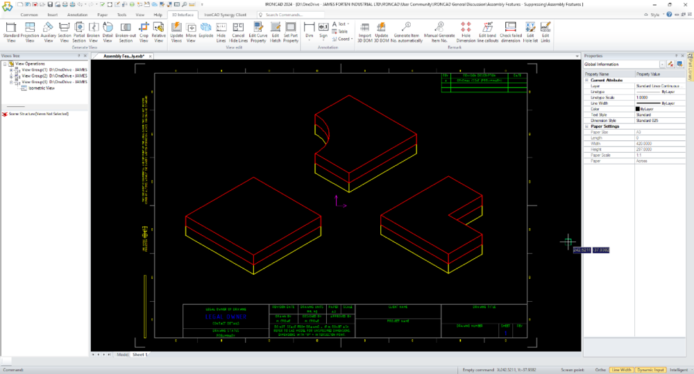
-
CAXA - Broken out section on isometric
Malcolm Crowe replied to PWATSON's topic in General Discussion
Hi Logan, The important thing to keep in mind regarding "Assembly Features" is that they are Features (Intellishapes). Therefore when you create Configurations for controlling the suppression state of these, you need to select the option "Track suppression of Intellishapes ...". See the attached image. I've also attached a video demonstrating the process. Note that this isn't the only way, but it is the easiest. The other way doesn't require this option selection; but it involves setting up Suppression Parameters and Design Variations. This is more involved, which is why I've chosen not to demonstrate it, Malcolm Assembly Features - Suppressing - Configurations.mp4 Assembly Features - Assembly.ics Assembly Features - Red Part.ics Assembly Features - Yellow Part.ics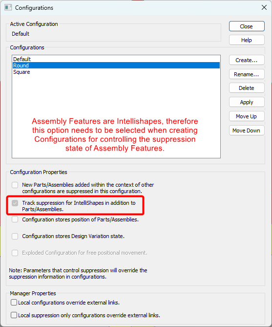
-
Point Clouds (PTS) - How to Set the Import Units?
Malcolm Crowe posted a topic in General Discussion
I have a Point Cloud (PTS file format) that imports at the wrong scale (x1000). How can I set the import units of Point Clouds? Our other software provides us with the option to choose the units when importing Point Clouds, but I can't find an option within IRONCAD. Malcolm -
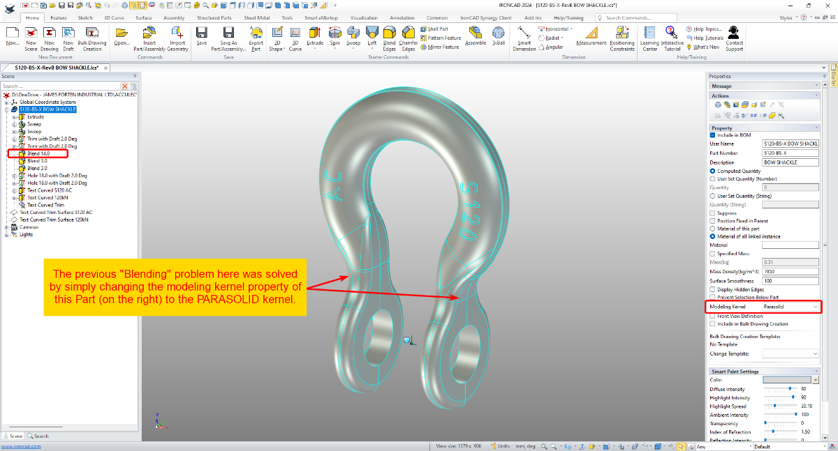
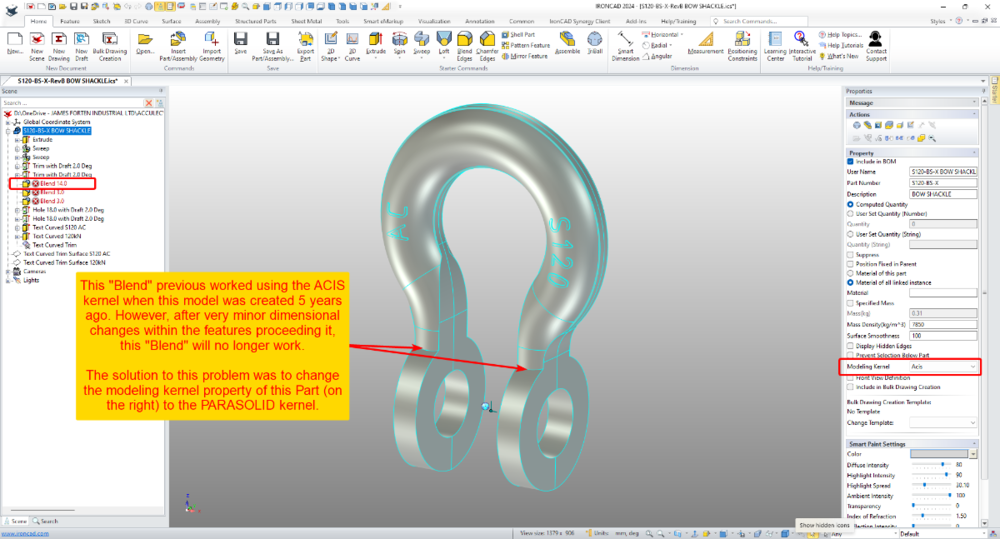
This is an interesting example from yesterday, where it was necessary to change from the ACIS kernel to the PARASOLID kernel for some Blends to work. This model was originally created 5 years ago (using the ACIS kernel), but after some very minor dimension changes yesterday, these Blends stopped working. Changing the kernel property of the Part to using PARASOLID solved the blending problem. Malcolm IRONCAD - Blend Problem Solved Changing from ACIS to PARASOLID Kernel - 20240313.mp4

-
Hi Kim, IRONCAD (CAXA) 2024 introduced the capability to have multiple "Papers" within a single tab. This was introduced specifically with the "Model" tab in mind (like the example in your image), but it is also applicable to the "Layout" tabs as well. Attached is a video demonstrating the principle of how this works. Regarding what file format to use in CAXA, we normally use CAXA's *.exb file format. We only save as *.dwg when we need to collaborate with other CAD software (like BRICSCAD that we also use). This might not be 100% correct, but I've noticed that when *.dwg files are used (instead of *.exb), then the dimensions applied to Generated Views within CAXA are not associative. That is, if the 3D Model changes and the Generated View updates, then the dimensions in CAXA don't follow as they do for *.exb files. It's more efficient to annotate drawings of IRONCAD Scenes within CAXA (with full access to 3D properties as well), rather than externally referencing into other software for this purpose. However, when you need to incorporate associated Generated Views from CAXA within 2D Models of other CAD software (like AUTOCAD, BRICSCAD, MICROSTATION, etc.) then externally referencing *.dwg files from CAXA is a good option to have. Malcolm CAXA - Multiple Papers within Model Space.mp4
-
Hi TaeGyu, The link below is to a new post created with your question in mind. 1. IRONCAD Scene (*.ics) 2. CAXA DRAFT Generated Views (*.dwg) 3. DWG Editor (BRICSCAD) externally referencing the Generated Views from the CAXA drawing. But why not just create the fully annotated drawing in CAXA? This would be more efficient, and you don't lose access to the 3D property information needed for BOMs. Externally referencing Generated Views from CAXA DRAFT is really useful if you're combining these within another drawing (like a building layout, etc.). But it is a more complicated workflow if all you are doing is annotating the Generated Views. Malcolm
-
One of the strengths of DWG Editors (like CAXA, AUTOCAD, BRICSCAD, etc) is the ability to externally reference (XRef) other DWG files, in a similar way that we can externally reference other 3D Scene files within a 3D Scene. This is hugely beneficial when DWG files from multiple users (or engineering disciplines) are combined into a common layout. An example could be the layout of a machine or production line (designed in IRONCAD) that needs to be overlayed with a building layout (and other services). The attached video demonstrates how Generated Views in CAXA can be saved as a DWG file, that can then be externally referenced (XRef) into other DWG files, within another DWG Editor (in this case BRICSCAD). When the 3D Scene changes, the CAXA file needs to be opened so that it can be updated and saved. Then within the other DWG Editor the externally referenced CAXA file needs to be "Reloaded" to update the link. The XRef then needs to be "refreshed" by editing a property of the XRef (such as layer, color, etc.), so that any associated dimensions correctly update. Malcolm CAXA - Referencing Generated Views as XRefs within other DWG Editors.mp4
-
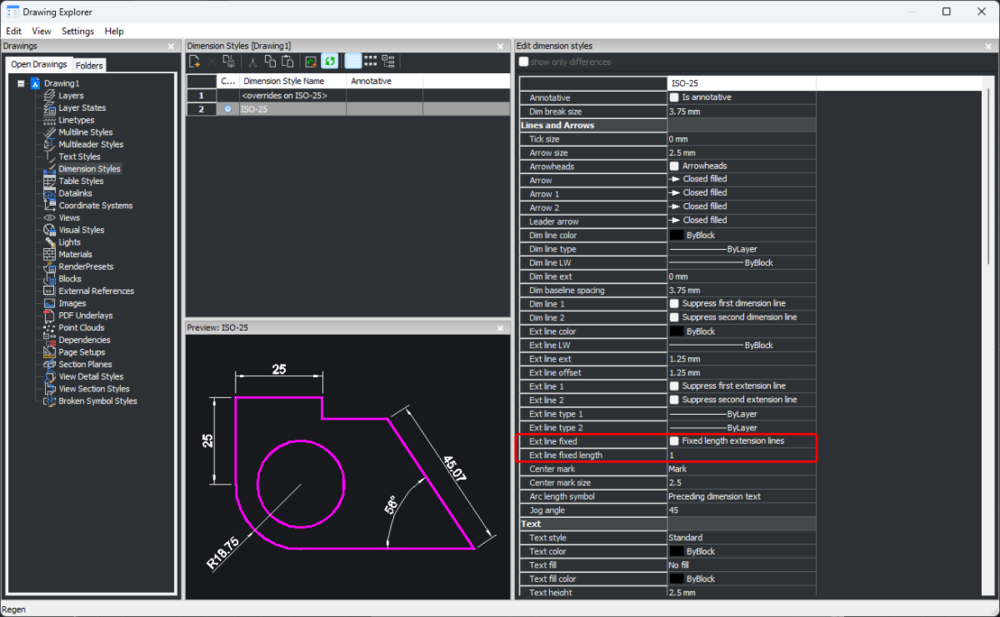
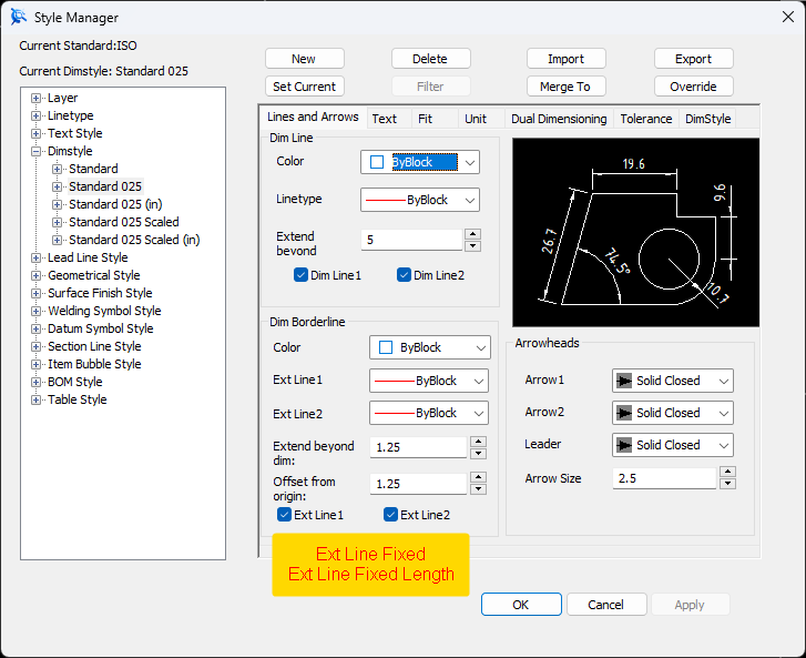
Some DWG Editors (based on the ODA Drawing SDK) include two settings for fixing the length of Dimension Extension Lines, as an alternative to the normal offset from the selected geometry. While CAXA hasn't implemented these two settings (currently), the attached video demonstrates how to achieve the same end result by turning off the generated Extension Lines, and manually adding Fixed Length ones using CAXA Symbols (Library). Malcolm CAXA - Manually Adding Fixed Length Extension Lines.mp4
-
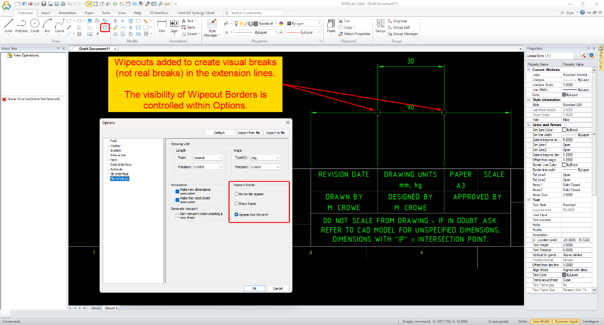
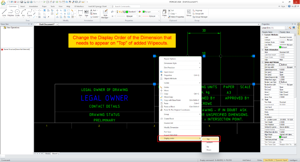
CAXA - Extension line break when dimensions cross.
Malcolm Crowe replied to PWATSON's topic in General Discussion
Hi Peter, While there isn't a specific tool in CAXA for this, the attached video demonstrates how to create Visual Breaks in Extension Lines using Wipeouts (to create the same end result). Malcolm CAXA - Using Wipeouts to Add Visual Breaks to Dimension Extension Lines.mp4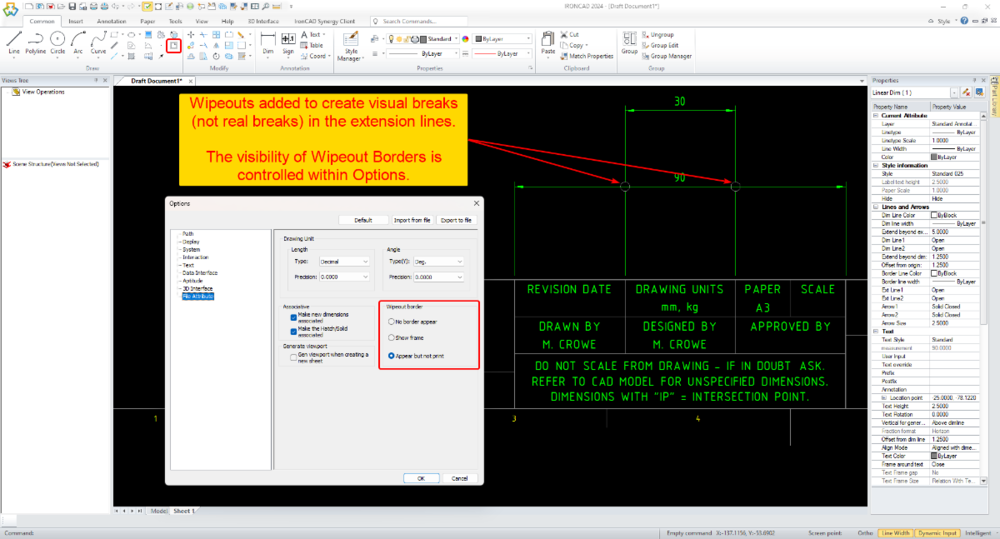
-
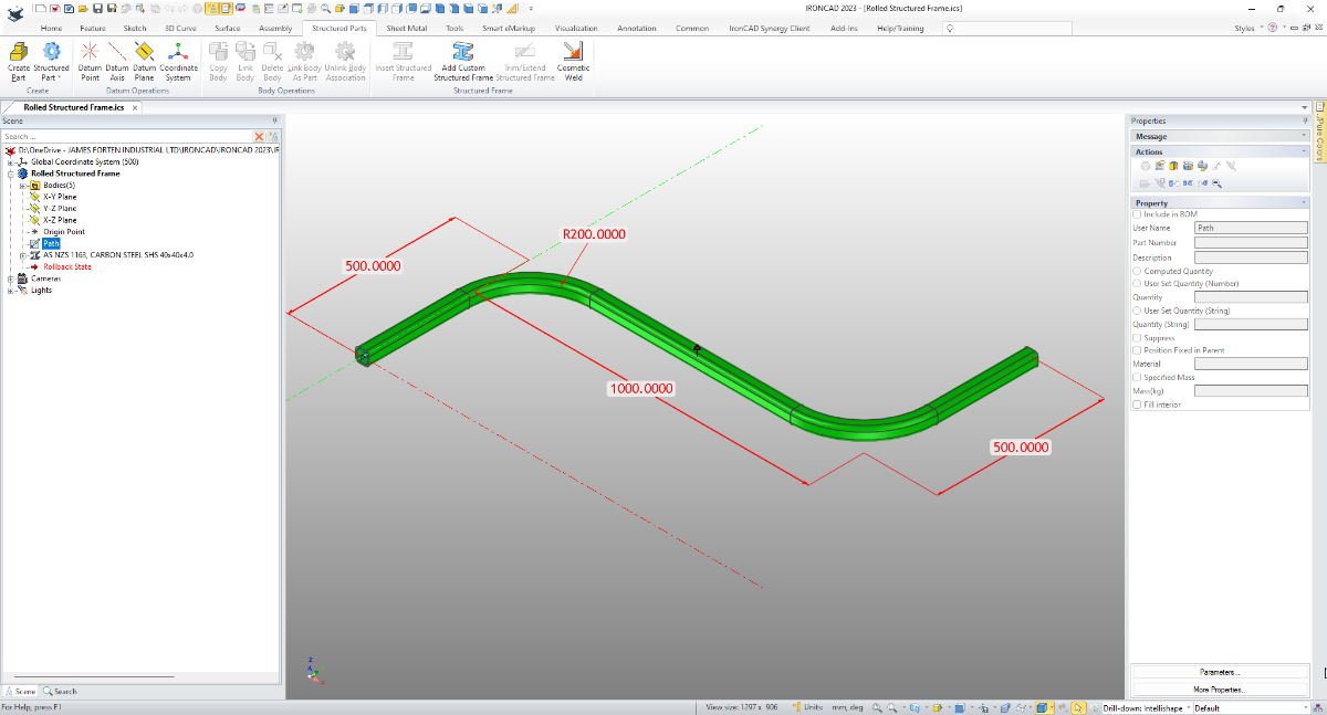
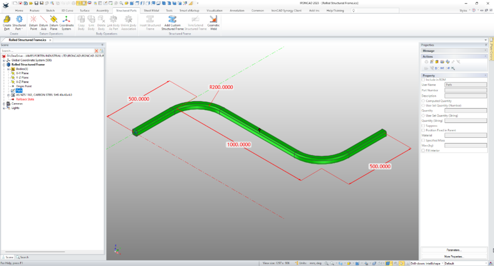
The "Structured Frame" tool is well suited for this. Create a new "Structured Part" and within that create a sketch of the "Path" that you want the Structured Frame to follow. Then use the "Structured Frame" tool to apply the desired section to that sketched path. See the attached video. Malcolm Rolled Structured Frame.mp4 Rolled Structured Frame.ics
-
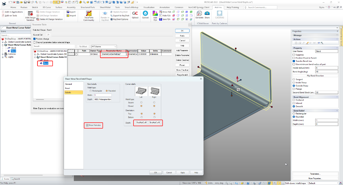
Hi Harley, I've tried to demonstrate how to control Bend Corner Reliefs via Parameters in the attached video. It's important to add the Parameter(s) first at the Feature (Bend) Level. Then you can reference that Parameter Name in the Bend Properties. Malcolm Sheet Metal Bend Corner Relief Parameters.mp4 Sheet Metal Bend Corner Relief Parameters.ics

-
Can I Add color at the assembly level only
Malcolm Crowe replied to PWATSON's topic in General Discussion
Hi Peter, I'm pleased to hear that it was helpful. For the sake of other users (who aren't necessarily interested in changing colors), the principles demonstrated in the video are applicable to any type of Design Variation (including sizing, suppression, and properties). Malcolm -
Attachment Point Connector - Default APs Limit Selection
Malcolm Crowe replied to Malcolm Crowe's topic in General Discussion
Thanks Kevin, that's good to hear. Malcolm -
Can I Add color at the assembly level only
Malcolm Crowe replied to PWATSON's topic in General Discussion
Hi Peter, The weather hasn't been favorable for cycling (one of my fun things to do), so I've been working today. It helps that my wife is away working this weekend as well. Attached is a video that I hope demonstrates well enough what is possible with "Design Configurations" and "Scene Configurations". I've also attached the Scene files used in the video. One of the great things about "Design Variations" is that they are saved with the Part (or Assembly), and not with the Scene. As a result, "Design Variations" are saved with the Part (or Assembly) when dragged into a Catalog. This is not the case with "Scene Configurations" (which are Scene specific). Malcolm IRONCAD - Design Variations - Applying Colors.mp4 ASSEMBLY.ics PIE.ics PYRAMID.ics SPHERE.ics SUB-ASSEMBLY.ics -
Can I Add color at the assembly level only
Malcolm Crowe replied to PWATSON's topic in General Discussion
Hi Peter, If you're using externally linked Parts that are inserted into Assemblies, then the following might work for you. However, you need to be aware, that it's not possible to have different colors for the same Part within the same Scene. "Design Variations" allow you to assign specific colors to each DV if wanted. So, for your Parts you could have "Painted" and "Unpainted" DVs. Then when you insert one of these Parts within an Assembly, you could use "Add to Active Configuration" within the "Design Variation Dialog" to link the desired DV of the Part (Painted or Unpainted) to the current Configuration of the Scene (into which it has been inserted). Let me know if this doesn't make sense, as I can potentially make a video in the weekend. Malcolm