HDEAR
-
Posts
1,017 -
Joined
-
Last visited
Content Type
Profiles
Forums
Blogs
Downloads
Articles
Gallery
Everything posted by HDEAR
-
It would also be handy to locate all ICS files that the CAXA ( exb ) files relate to.
-
 Thanks Kim, I was hoping to avoid the sketching, particularly the sketch bends as I find it difficult to control the dimensions and placements somehow. Maybe I need to practice a lot more? Cheers - Harley
 -
Hi all, If you convert a sheetmetal file from another programme, it's all well and good to be able to go an add features like holes and bends to the newly formed ICS sheetmetal part. However, if you want to change some basic dimensions to the shetmetal features of the actual converted part, this seems imposible. Or, is there a simple way to go about this? Harley Changing convert to sheetmtal parts.mp4
-
Selection drop down problem in CAXA Attribute column
HDEAR replied to HDEAR's topic in General Discussion
Sorry Kevin, I've been a bit distracted. I'll email it to you shortly. -
Hi all, Both my work colleague and I have problems with the Attribute column drop in the title block down taking several clicks before it works. It's annoying. It should just offer the drop down arrow once it's clicked. See video Does anyone else get this problem? Can it be fixed? Harley CAXA Title block attribute name auto selection problem.mp4
-
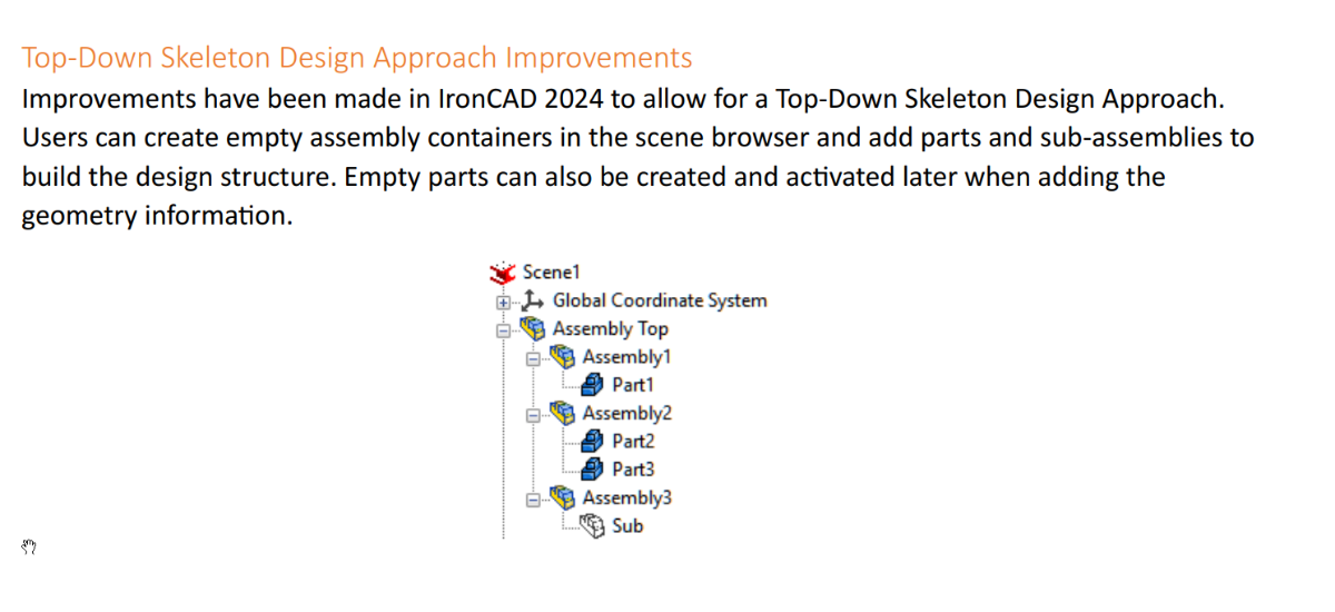
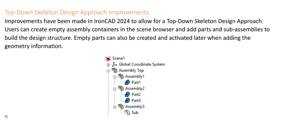
Hi IC Team, How do you go about creating these 'empty assembly containers' in the scene browser? How can you create an empty part and add later? It would be nice to have videos on all these new toys that IC has introduced in 2024 because you've spoiled us in the past with these Harley
-
Thanks Cary.
-
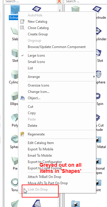
Hi all, I like the link on drop from catalogue option no available. Am I right though in thinking that not all catalogues offer that function? For example 'Shapes' doesn't seem to offer it. If that's so, how do you work out which catalogues offer it and which don't? Harley
-
Nice
-
Wallpapers for v2024 with and without a calender
HDEAR replied to emil.rindell's topic in General Discussion
Well done Emil. -
Season's Greetings to the Team and the Community
HDEAR replied to jolizon590016's topic in General Discussion
All the best to everyone for the Christmas festive season. -
Structured part - can't get sketch to lock to 3 points
HDEAR replied to HDEAR's topic in General Discussion
Nice - thanks Kevin. -
I brought this problem up a year 0r two ago and it was easily solved. I can't remember how, but if you look back on my posts, you'll find the thread.
-
On their way
-
Hi all, I have added center lines to a layout. Because the circular parts are from sheet metal and not complete circles, I cannot have center lines automatically added when bring in the view from the 3D scene. However, whenever I update the EXB, I loose the centre lines I added. Damned frustrating, it is. Disappearing centre lines.mp4 Disappearing centre lines.mp4
-
Hi tgjang. This topic came up a while back. I found this but can't find the post I made that I referred to in this particular post link. https://community.ironcad.com/index.php?/topic/15520-caxa-problem-re-attaching-dimension/#comment-59247 I will keep looking for you. Harley
-
Sorry Kim, unclear English syntax. I meant the bend corner reliefs that are the type that you would normally use to create closed corners and suchlike. Harley
-
Perfect - thanks Malcolm.
-
Bump!
-
Thanks Kim. I missed selecting the feature first and 'lock' also . Thanks Cary, I'll look at that but in complex scenes I have found ICMECH slows things down a bit. Also, the distance that the tab is set in from the start ( or end ) does not show up in the parameter list using ICMECH.
-
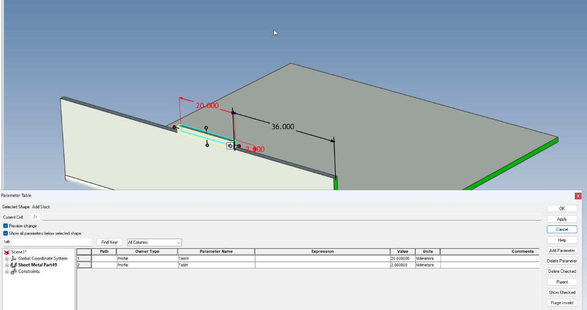
Hi all, I have a bend, on top of which I have a location tab. The tab is made from 'Add stock'. Because the bend profile itself cannot be edited with '2D sketch' the only way to position it is with a smart dimension, which is all well and good unless you want to drive the design of the part using parameters, which is what I want to do. I have given the tab its H and W parameters, but I would like to have a parameter for positioning as well ( the 36mm in the pic ). What's the best method of applying that positioning dimension as a parameter? I have tried 'Assembly/Positioning Constraints but cannot select the target entity face ( edge of the bend or sheet ) even though I can select the source entity ( face of the sheet metal tab ). Similarly, how would you make a parameter for positioning the matching slot ( on a bend on another part )? Positioning tab.mp4

-
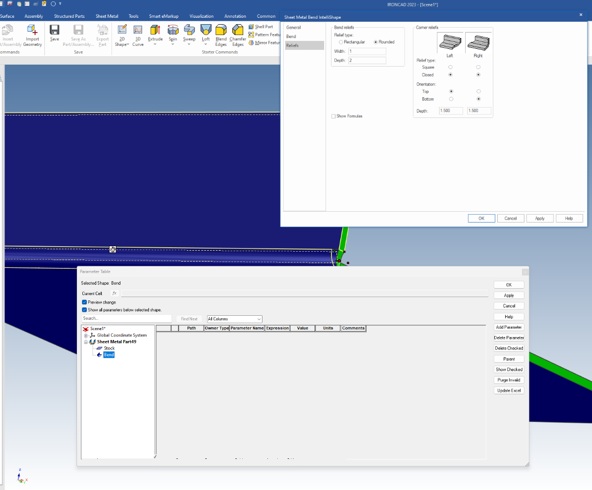
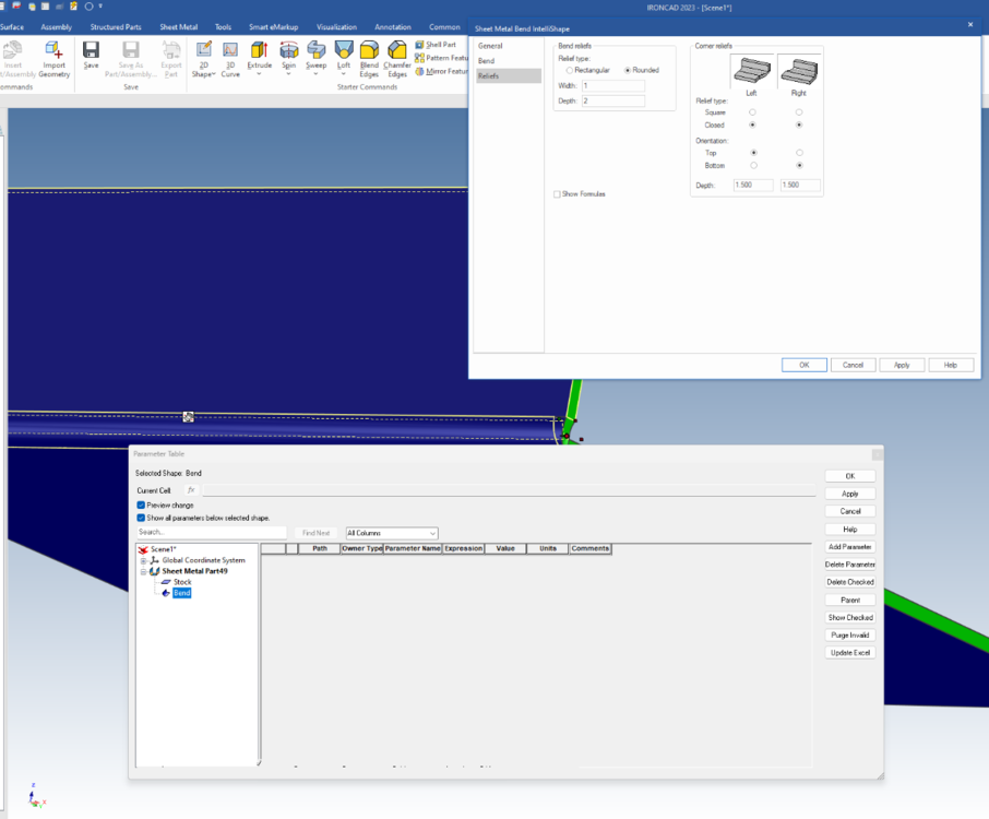
Hi all, Weird question I know, but is it possible to have the closed type bend relief values show in the parameter table? In this example below, Top=1.5mm, Bottom = 1.5mm. At present it doesn't seem possible. Many thanks, Harley
-
Well done on your 'Rocket Sprocket' Kim. Do you think it would be worthwhile making a training video for this with just the vital steps? Harley
-
Fold directions on saved parts from scene incorrect.
HDEAR replied to HDEAR's topic in General Discussion
Hi Spencer. Kevin thinks it has something to do with the sheet being mirrored. How this came about ( being mirrored ) I do not know, but this particular part shape has been used in various assemblies and it has grown a little like GrandMa's axe. Now I have the Mirrored parts filter on in the scene tree, I can keep an eye out for it. Harley -
Hi all, attached Incorrect fold directions on saved part.mp4 The video is self explanatory. I have a scene with various s/m panels. I noticed one of the panel I had 'saved as a part' has the bend direction incorrect on the saved part compared to that in the scene. The panel featured mitred bends and can't be fixed by simply reversing the bend direction. The files have been sent to Kevin and Cary to see what they can glean. I wondered if anyone else had struck this problem. ****UPDATE*** Kevin pointed out the part in the scene was mirrored, so now looking at what caused this and if there's a work-around. Harley