


ASPEER
-
Posts
53 -
Joined
-
Last visited
Content Type
Profiles
Forums
Blogs
Downloads
Articles
Gallery
Everything posted by ASPEER
-
For test 13, that is working as it should, you are multiplying a scalar (unitless) by a length. For test 14, that is a bit odd, however I suspect it is because they expect the numerator to always have units. The result is exactly as expected for 1m/1mm=Xmm if you consider the conversions done, ie 1m/0.001m=1000m * 1000=1 000 000mm.
-
Kim, default units in the parameter table is meters, if you specify a unit then it will use that unit for that particular variable. The units column is the display units for the evaluated expression. Scalar values are unitless and as such are converted to default units (meters) before addition or subtraction are performed.
-
what you could do is have 2 linked parts to control the thread or final part dimensions and use assembly features to add and remove parts from each so that they can mate together.
-
I have all my files on Onedrive, and there are no issues, but then I dont have other people wanting to edit the files either.
-
You can edit linked parts, but editing one will edit all linked parts. Any change made to one will be made to all of them. So you would essentially have multiple copies of the one part, although they may be mirrored. You could have the features you want copied to be made with parameters.
-
Getting slot to move with sheet-metal length change
ASPEER replied to HDEAR's topic in General Discussion
Under Assembly, positioning constraints will be able to lock its distance. You may also need to lock the constraint through. -
There is a tool like that in sweep, but I am not sure if it has all the same features.
-
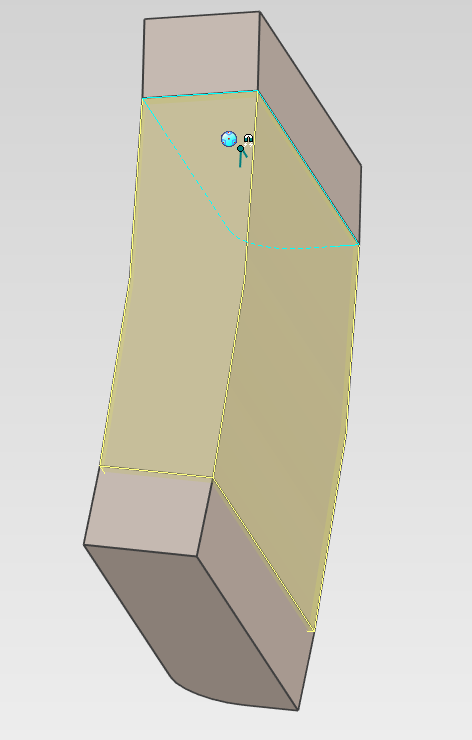
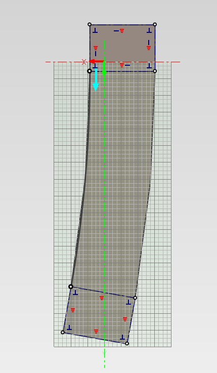
That is normal behaviour from my experience. Usually when I want to move the triball to a part of the cut I move the cut into a solid then move the triball to the point. I havent tried moving the camera around a cut shape, but neither would I expect it to work.
-
The webviewer has added another hole in the assembly, and given it's placement (in a pattern part) it would follow that it converted the assembly feature hole into a part-feature. IC2021 sp2. http://share3d.ironcad.com/5CB439C593135FCEA2EF442DF49DCBB61ECD77BD48337743FEEE59AD9CBE2925/917c6811-ce3c-471d-ac4b-a38554f6b373.html Opp no 52277.ics
-
Is there a difference between Kiwi and Aussie regional settings, because it seems to work fine for me. Running 2021
-
Thanks Cary, that works.
-
I am trying to make some sheet metal profile blades and want to add a large chamfer on the non-cutting sides, however, chamfer and sweep don't like the small radius and large cut. Is there a good way to get around this? In IronCad 2021.00.01 I should mention. 28mm rib Guillotine b.ics


-
The feature you are looking for is "boolean" it allows you to add or subtract parts to and from other parts.
-
If you right click on the feature with the intellishape selected you can select feature options which will allow you to select whether you want to add or remove material in the properties tab.

-
you can make a hole extrude to remove the section you dont want, you could even make it follow a curve so that the two blends are continuous, or perhaps a better option would be using a sweep with the side profile you want and have it sweep from face to face.
-
If you bring up the Create a Sweep menu (right click on the sketch, create, sweep) you can choose to remove material there.

-
I recently sent a toolmaker a drawing in .dxf and he said that the text in it lost all formatting and became essentially illegible when he tried to open it in Autocad 2014. I have attached what the toolmaker sent back saying he gets when he opens the .dxf, the .dxf file I sent (autocad 2013), and the .icd file I exported it from. Ironcad opens the .dxf perfectly fine. I am using IronCad 2021 (not SP 1). Doc3.doc 28MM RIDGE ASSEMBLED.DXF 28mm ridge assembled.icd
-
Attachment Points - Expressions Needed for Orientation (3 Axes)
ASPEER replied to Malcolm Crowe's topic in General Discussion
Looks like some matrix transformations are needed here, and unfortunately my matrix maths is a bit rusty so it may be easier for you to look up what you need down that path. The axis numbers look like eigen vectors but again my matrix maths is rusty so I may be wrong. This would be helpful: https://en.wikipedia.org/wiki/Rotation_matrix -
Thanks, looking forward to it.
-
Trying to resolve some of the issues, I decided to simply mirror some working assemblies, however, given the parts are chiral/sided I would need to adjust the attachment points to match the intended connections. When adjusting the points I tried to mirror them but the command didnt seem to take. I uploaded a video illustrating what I mean. 2020-11-06 10-17-40.mkv


