doodah
-
Posts
3 -
Joined
-
Last visited
doodah's Achievements
New Member (1/9)
0
Reputation
-
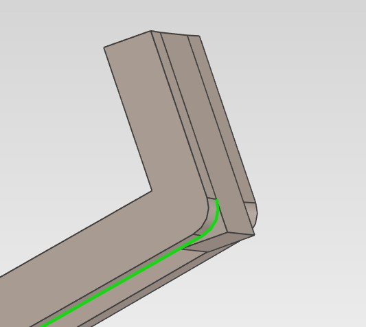
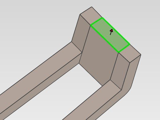
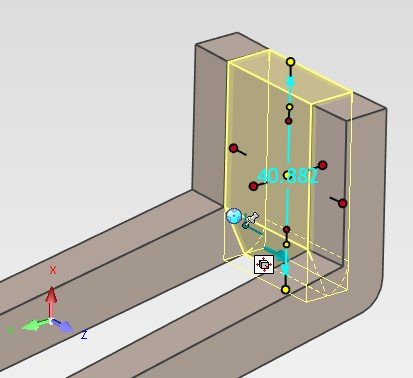
Sorry for the delay in responding all. It's been a busy couple of days in the real world. So I really appreciate all of the suggestions, and I think I'm slowly getting to grips with the basic sketch manipulation. I now appreciate the split function and how it's more-or-less the same for operations like this. So, I realise @SSIMMONS I didn't do a great job of explaining what I meant by my need to edit the same volume on two sketch planes. Even if that's possible (or not), I'm willing to bet at this stage you guys have a better way of doing what I'm trying to get to. (Again, really appreciate your guessing at what I was trying to explain with those vids). I'll try and explain things a bit clearer this time - with images! Now I have the joining part added as I was trying to do originally. The face I've highlighted is a trapezoid and meshes with the two angled pieces either side perfectly. However, the "other plane" I mentioned was the side profile of the part, where I want it to match the curve of the side parts, like this: I've played around with some multiple point chamfer and blend edges, but I can't get a good result. If I could edit this side as a cross section, then I'm sure I would b e able to add points and match it up perfectly. So this is my current issue.
-
Thanks Spencer - Actually that does answer the question and your insight into weld joints is really interesting. Perhaps I should have explained that my whole reason for getting into IronCAD was for 3D printing as the interface seems so much easier to get to grips with from other CAD / modelling software I've experimented with. The part boundaries need to be pretty exact, and your video explained precisely how to do this so thanks for taking the time to record that. My issue is now that I can't edit the sketch in the plane I want. Your video actually showed you had the same problem and re-orientated the block to get the sketch plane right, so that suddenly clicked that the orientation of the part is linked to the edit cross-section orientation... My new issue is that I shaped the joining block with it's cross section on the x-y plane, so that it has a specific shape in-situ. I need to edit the cross section in the y-z plane to mimic what you did in your video but can't rotate the part to do this without messing stuff up. I've tried searching for the answer, however I can't seem to find this particular scenario. I guess what I'm asking is; can you edit multiple plane cross sections for the same part?
-
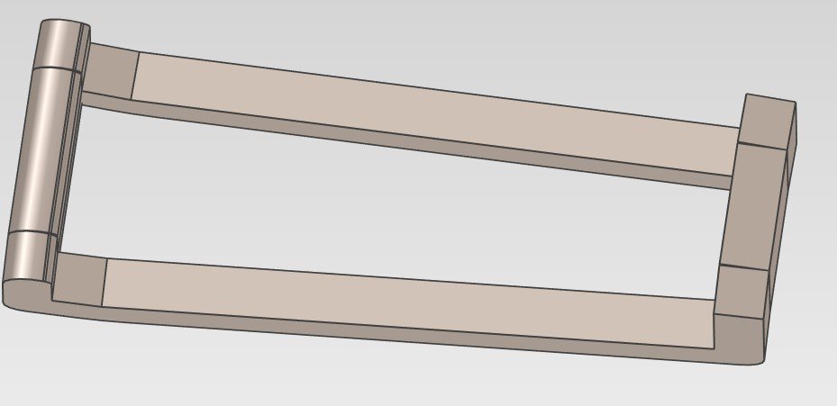
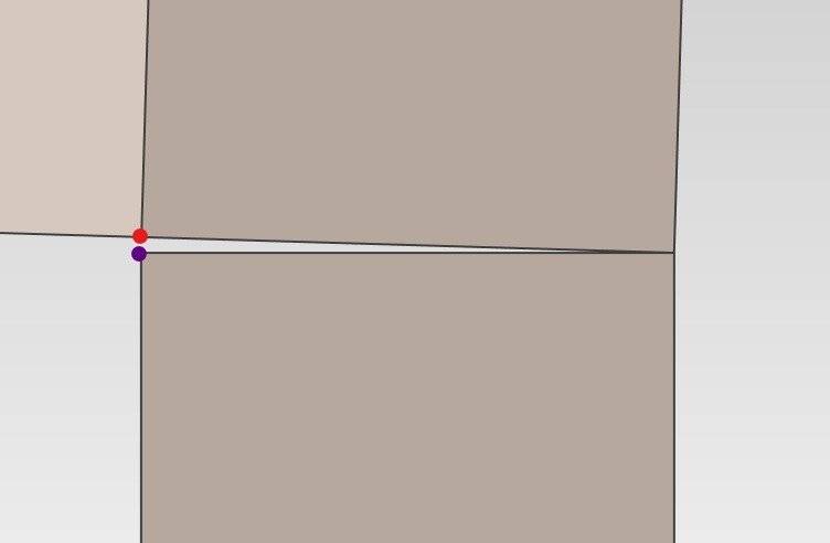
I've been following some tutorials and have got myself stable in some basic understanding and manipulation of the geometry, however all of the examples have nicely aligned parts, which is unfortunately different from my experimental real-world project. In my head, I'd want to move a vertex by deforming the shape rather than moving an edge or face (moving the purple vertex to the red one in my screenshot). You can see that the front (left side) is wider than the rear (right side), which, when rotating the two sides inwards equally has created a very small overlap in the front connecting piece and a gap in the rear piece. What's the common practice or technique for dealing with this?