


ASPEER
-
Posts
53 -
Joined
-
Last visited
ASPEER's Achievements
")
Cylinder (3/9)
3
Reputation
-
Kim, you may have to recreate a rounding function. The easiest way would be INT(2 x DEGREE - INT13). Basically the idea is to take the integer of the truncated plus twice the difference of the original and truncated numbers.
-
I can see that your sizebox has become offset from the actual shape, I certainly encountered that a lot when I was setting up my smart model, but the only way I remember fixing it was to literally backtrack to before whatever change caused it. There may well be better ways but I didnt find them. Your parameters look a bit odd to me, but that might be my inexperience. All your equations are integer based, which iirc round down, so the section of missing components looks like a working as written scenario to me. You should add a remainder fill section to your parameters and model, typically I would make this section always there and with range of [0,1) unit (if I read correctly 96" in this case), unless you want to have the model move in steps.
-
I strongly suspect I did something similar when I made a few of my smart models, however, fortunately for me the orientation doesnt matter. I think you may be able to fix this issue if you delve back into the construction of your smart models and re-orientate your sizebox part so it aligns with how you want your model to work (or the other way around depending on what is easier). Another option would be to change what your parameters are pointing to. Now I think on it does your model expand in a different direction to what the handles drag the sizebox to?
-
Is this the video you were after? https://ironcad.academy/tutorial/what-are-smartmodels
-
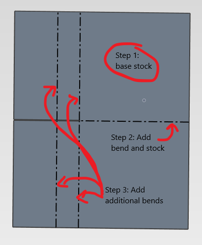
Aleman, I edited the image I posted above with the steps I took, but simply said I added each section one by one, rather than adding a section and then trying to bend it. The bends were dragged from the catalogue.
-
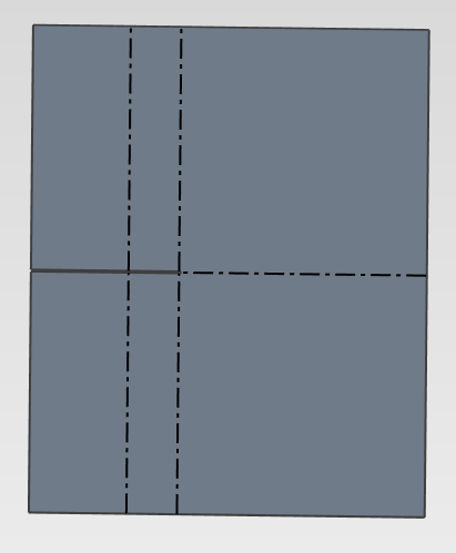
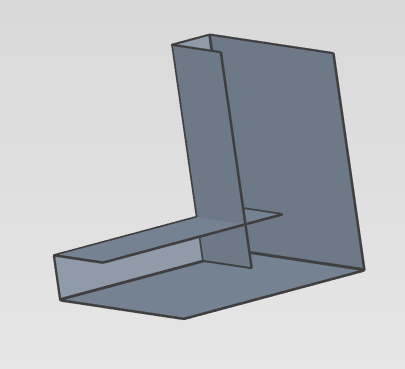
Aleman, for the first one you are attempting to make, if I understand you correctly, you want to have a cut along the horizontal bend line to separate the top and bottom halves of the vertical bends. It is my understanding that this will work just fine if you model it like you would make it, ie cut the notch before you bend it horizontally. If you want to model to work out what the notch should look like, you can not model a V at first, just a break between the different sides of the bend and remove the overlapping material later. I attached a couple images of what I recreated from your post. I made it from bend and stock parts, base stock in top right and then built out from there. Andrew
-
I am curious why you would use an air tool as a base for an electric tool, personally. Unless Lee meant air drill (the base looks like a screwdriver or impact driver). The way I would tackle the problem would be aalbe's method, but that is due to simplicity.
-
I use a crude RHS intellishape made from a shelled extrude with rounded edges. SHS is a rather simple shape so if you only need to have a representation with written in details it should be quick and easy.
-
Very nice Kim. Coincidentally I was looking at doing something similar myself, and in my research I came across a couple of technical details. The worm gear wheel needs to have a bit of space around the worm for the lube, this is usually done by either using a slightly larger cutter, or making a couple passes slightly offset from each other. The other concerns the worm, in that they often control the backlash in worm gears by having slightly different pitches on either side of the worm's tooth (teeth). I also note having more turns in your sweep cut would change the tooth profile slightly, towards a more involute profile.
-
Kim, it looks like the issue is with the units. Test23 has units of mm2 but it looks like the conversion from default units (m) to mm only accounted for linear units (m => mm) rather than area units (m2 => mm2). Test24 is unitless and has been converted to mm.
-
This looks like a Two Points blend use case to me.
-
The way I typically would do something like this is use the triball link the identical members to position. Typically the most difficult part to this is getting the distance between each right, however given you have the sketch, that info is readily available to you. The specific steps I would take: Take the brace and mirror it to the reverse position (rotate works too) Select the second, and translate both of the braces to fill the pattern Delete the excess brace Now the braces are linked.
-
Most of those braces look identical just orientated differently, if they were linked rather than copied/new instances, the property info would update automatically as Ironcad considers them multiple instances of the same item.
-
Another cause may be that the assembly is offset from the sizebox, unfortunately in my experience this requires a larger fix than the methods Kim put forward, so try those first. If this only happened on this assembly, I would delete and pull another out from the catalog if it is stored. Only after I determine that it is a model issue do I properly debug the model.
-
I opened a new scene and it was unable to save as well. Restarting the computer seems to have fixed the issue, although I will have to recreate the document.

