


GNÄSLUND
-
Posts
59 -
Joined
-
Last visited
Content Type
Profiles
Forums
Blogs
Downloads
Articles
Gallery
Everything posted by GNÄSLUND
-
How to Prevent SmartDimensions from Flipping Direction?
GNÄSLUND replied to Malcolm Crowe's topic in General Discussion
Hi Malcolm, I did some testing and I think that if you dimension from the top surface and not the edge it will work. -
Yes, that is an awesome shortcut Another tip is Alt+click to direct-select feature or intellishape
-
Try to put things that should move together in a subassembly
-
Importing - Reorientation of Sizebox Height etc
GNÄSLUND replied to Malcolm Crowe's topic in General Discussion
Looks like the "&" is not needed. This seems to work consistently =MAX( Shape\Sizebox\Length, Shape\Sizebox\Width, Shape\Sizebox\Height ) -
Importing - Reorientation of Sizebox Height etc
GNÄSLUND replied to Malcolm Crowe's topic in General Discussion
Yes, there seems to be something odd. I have tried adding the custom property several times now and sometimes it works and sometimes it dont. -
Importing - Reorientation of Sizebox Height etc
GNÄSLUND replied to Malcolm Crowe's topic in General Discussion
It works for me with at simple box part. See attached file and video. You can send me an example file if you like and I can try it from here Y3qep2mssH.mp4 StockLength.ics -
Importing - Reorientation of Sizebox Height etc
GNÄSLUND replied to Malcolm Crowe's topic in General Discussion
Correct me if I am wrong; but I understand that you want to be able to automatically extract the stock length of the imported tubes, regardless of orientation? A workaround that comes to mind is that you could make a Custom Property expression that gives the maximum of [Length, Width, Height] as result. =&MAX(Shape\Sizebox\Length;Shape\Sizebox\Width:Shape\Sizebox\Height) That would give you the stock length most of the time. -
I don't think you can't fold that curve with the sheet metal tools. It only works with "developable surfaces", see https://en.wikipedia.org/wiki/Developable_surface You can however model it in IRONCAD in its "folded" state with ordinary modeling tools. Extrude -> shell -> cut away excess material. And then create a drawing that can be used to manufacture the part. To manufacture it you either need to use manual forming tools (shrinker stretcher, etc) or machine a press-forming tool.
-
You can not use the triball to get an associative mirror of the bend. You can however use Feature -> Mirror Feature and use the edge midpoint as the mirror plane.
-
It all depends on how many display output connections you have on your laptop. I am running three screens from my laptop Albeit via a docking station. Straight from the laptop I have two outputs; HDMI and DP (displayport). If you have modern screens with DP-connections and you can also "daisy-chain" several screens to the same DisplayPort-output.
-
Can Dimensions / Smart Dimensions "drive" part size?
GNÄSLUND replied to Macktek's topic in General Discussion
You can also try adding the dimensions in the cross section sketch. They can then be edited from the 3d scene -
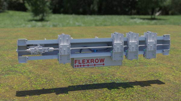 Demonstration project of using the novel HILA hydraulic technology in an agricultural application. * Modelled in Ironcad 2020 * Rendered in Blender 2.82 using Cycles * HDRI lighting from hdrihaven.com * Textures from texturehaven.com
© GN Tech AB
-
How to make mechanism mode respect assemblies
GNÄSLUND replied to BrentMckelvie's topic in General Discussion
Recorded a small video to perhaps explain a little better. Untitled_2.mp4 -
How to make mechanism mode respect assemblies
GNÄSLUND replied to BrentMckelvie's topic in General Discussion
Hi! My experience is that Ironcad will respect your assemblies as glued as long as the part you click and drag on with mechanism mode is part of at least one constraint. If you click and drag on a part in an assembly that has no constraints whatsoever it will rip the assembly apart as you describe. -
How to make a blend as an assembly feature
GNÄSLUND replied to BrentMckelvie's topic in General Discussion
This can be achieved using "Link Body As Part" found under the Feature-tab. 1. Go to "Structured part"-mode. (Must be done in structured part mode) 2. Create the profile cut part and save it. 3. Expand the part in the scene-browser and select the body. 4. Click "Link Body As Part" found under the Feature-tab. 5. Choose where to save the new file (that will be machined) 6. Open the new file and do your machining operations. To verify that it works: 1. Go back and edit the profile cut part, save 2. Go to the machining part. The base part should now ask to update. I can record a short video later if you need more guidance. -
Tips: If you select the front view when creating the BOM, you can choose "Top Level Only". This might be what you actually want.
-
Save External > Edit in separate window > bring in Updates
GNÄSLUND replied to WPONG's topic in General Discussion
This does not really answer your questiuon but my five cents are: When saving part/assembly to external file, subsequent parts/assemblies in that file are not inserted as you describe. But when inserting an external file that contain more than one top part or top assembly the items are wrapped in an extra assembly when inserted. This took me a while to realise that this was happening. An idea I have is that when I insert an external file I should be able to choose between, "insert everything in file" or "choose a certain part/assembly" from the file to insert. -
Nice!
-
Here I have modified your scene to add a loft. It is a bit of a hack since the two sweeps are in separate parts but it looks alright. Ceiling tee rail suspension wire with loft.ics

-
Another important tips is that the ACIS-kernel is recommended for lofted parts since it can tolerate much greater deviations between the ends than Parasolid.
-
Have you tried using a "loft" to connect the two loose ends? I have attached a simple example where I have lofted between the ends of two arbitrary placed cylinders. (Try moving one of the cylinders with the triball) To be able to associate the loft to the two ends so it follows the tangent; the two ends need to be intellishapes in the same part. This is easiest done by setting the part as active when creating the second intellishape. Set start/end tangency to something like 20. See also this video for an example in a slightly different way loft_between_ends_example.ics


