


Macktek
-
Posts
15 -
Joined
-
Last visited
Macktek's Achievements
")
Block (2/9)
0
Reputation
-
Thanks. I can now see them.
-
Can Dimensions / Smart Dimensions "drive" part size?
Macktek replied to Macktek's topic in General Discussion
Thanks again Malcolm, I see that option is useful. But unfortunately, I don't think it solves the general problem that I can't seem to use Smart Dimensions in the scene to drive line lengths, angles, etc... (as mentioned in another post, when I smart dimension a line segment of a part, editing the size of the smart dimension doesn't do anything. (Perhaps there is a setting that I am not aware of, such as "Allow Smart Dimensions to Drive Part Features"?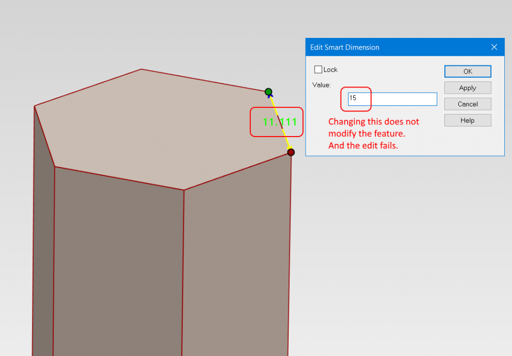
-
Can Dimensions / Smart Dimensions "drive" part size?
Macktek replied to Macktek's topic in General Discussion
OK so I am giving "Edit Cross Section" a try... and I am testing on a simple "Poly" from the shapes catalog in an attempt to make a Hexagon that I can adjust by simply typing in a dimension. So, I tried that but it warns me that "Any modifications to the profile will remove these variables and may yield undesirable results" (continue ?). I press yes, and continue. Adding the dimension allows me to adjust but, it deforms it out of shape, so I need to add constraints. I then add a set of angular and equal length constraints to the existing diagram, as well as 1 dimension across one of the faces. But when I attempted to use it, it gives me this error: (and oddly converts it into a rectilinear cube shape in preview)
-
Hello, Is there a way you guys can shut off or severely restrain this crazy forum search timer limit? When I am searching for information, its gotten to the point where I can't even press "NEXT" and I have to wait 12 or 14 or 8 seconds... its crazy.
-
Hello, When creating an "Innovative Part" and creating a Smart Dimension, for example between two edges on the face of a cube, it will display the current dimension (in this case 0.050). However, if I edit the dimension with a New Value (such as 0.1) , it goes thru the process as if it is being edited, but upon completion, nothing happens. How can I edit the Smart Dimension to change the Part Size? Or do I need to use another dimension type to do that? (I am aware of handles, but that's not the same as visible dimensions)

-
Hello, I am using the Smart Dimension Feature, but when I try to add another dimension or if I deselect my Part, the dimensions are hidden. I want to be able to set certain dimensions to always be visible. Is there a setting that allows me to "force" the dimension to stay visible even when the part is not selected? Or perhaps a global setting to "Keep Dimensions Visible" as a default ?
-
Hello Malcolm, Again, I really appreciate your efforts. I carefully watched your every step. AND I learned a lot. Definitely the First Method, using the Assembly Constraint is much faster and simpler than using the Triball. (So thank you for showing that!) As for the Triball method: that's A LOT of steps to use the Triball for something that should really be like 3 or 4 clicks!. As I watched you go thru the steps , there were many clicks and micro-manipulations to get where you wanted to be (and I counted ~12 just to just orient the face of the hexagon, not the chamfer). As opposed to other software, where I would simply press "C" for constraint, followed by selecting the face of the part, and then the "plane" of the coordinate system, followed by "OK". (And I am not here to argue about an extra click, but the Triball method is like 3 times more work). I really think that IronCAD has tremendous power, but sometimes the Triball idealogy gets in the way of simplicity... I will stick with the Assembly / Positioning Constraints method you showed first.
-
Dimension Sphere with Diameter Smart Dimension?
Macktek replied to Macktek's topic in General Discussion
I see. I really appreciate your efforts! -
IronCAD "Inovate" Brand Spelling consistency?
Macktek replied to Macktek's topic in General Discussion
Agreed! So why not call it "Inovative Part"? -
Hello, as a game developer, I frequently need my parts to be aligned to planes and for my part origin to be 0,0,0 or some specific location. Using "Innovative Part", I was able to figure out that I can set my part origin to 0,0,0 with the Triball. However, I am at a loss on how to align my Innovative part faces to the coordinate planes, such as constrain faces to be parallel to them, or to be ON the plane itself. This is required in order for the parts to be imported into the game in the "proper orientation" and position. Thanks.
-
I use Samsung SD850 Series 32" (LS32D85K) which is 2K. I found scaling the display to 128% in custom scaling to be optimal as IronCAD is a bit small on the screen for me. I really like these monitors. I don't have any issue with progressives on these monitors, but I am sure oureyes are a little different.
-
So, weird questions folks, as I am new to IronCAD, and I am just confused why IronCAD "Inovate" is spelled with one "N" but the "Innovative Part" is spelled with two Ns. For Branding, wouldn't you want to use consistency for that? or just go with a properly spelled word? (Its just confusing to see them both different). It also makes "searching" innconsistent (sic)

-
Hello, I am new to IronCAD Inovate, and I'd like to have visible dimensions on the parts, in this case of type: "Innovative Part" Dimensioning the Diameter for the top of a cylinder was no problem. However, I can't seem to properly dimension the diameter of a Sphere. Apparently, it picking some weird point opposite where I touch on the sphere and calling it a "Diameter" (Which it is not).

