


Umnik
-
Posts
15 -
Joined
-
Last visited
Umnik's Achievements
")
Block (2/9)
0
Reputation
-
Thank you Malcolm, great lessons!
-
That is helpful, thank you!
-
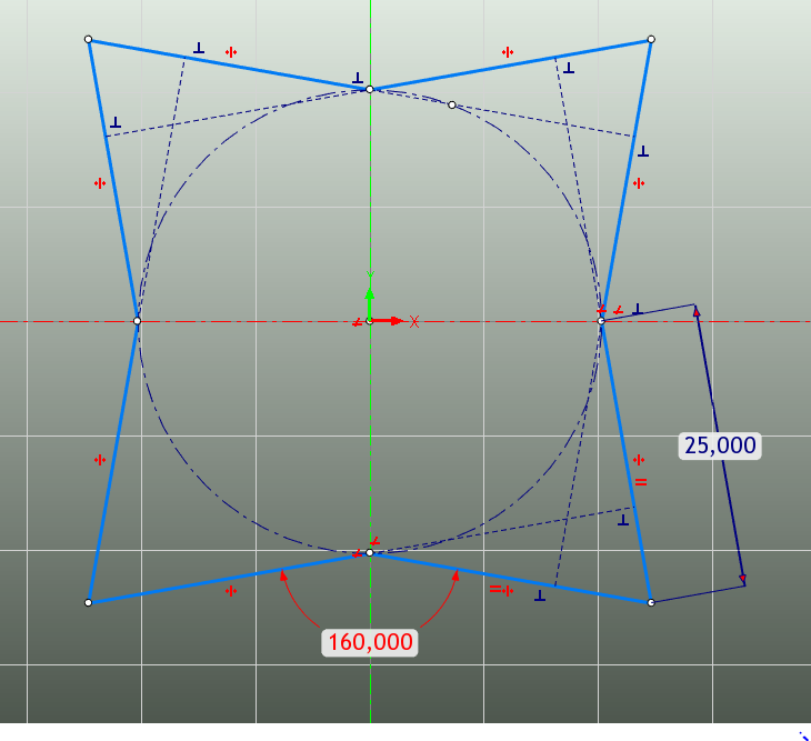
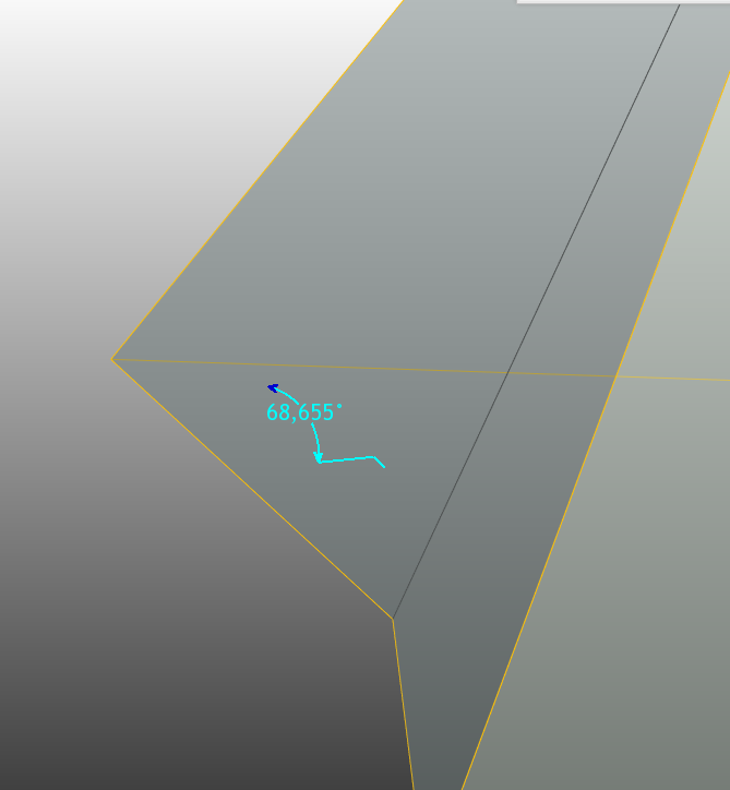
At the moment I can tell for sure that I need a video on how do you create your initial structured part from scratch). Then the geometry will be fully defined if we have both and the following angle between the faces (angle between base and any of the wall):
-
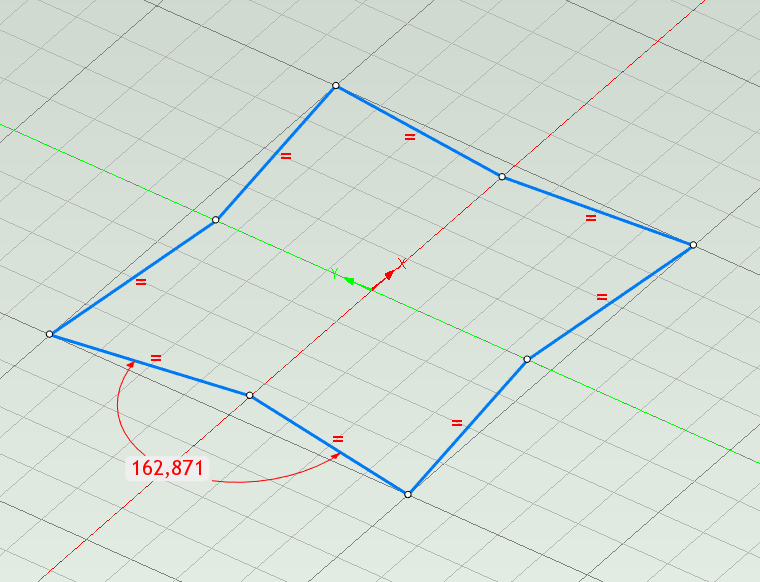
Thank you very much Malcolm! It is useful information for me. Now I have two problems: I cannot understand how exactly did you do that new pyramid cross-section based on a circle. Sketches in IronCAD are not so intuitive tool. The second issue is that I need directly set the pyramid faces angles, not via the height and width, because the precise angles are the main thing while developing the pyramid. Of course then I will measure all the final part sizes, but angles are main in this work. Therefore I cannot use the way you suggest, although the method you showed will be useful to me in the future. Due to the angles problem, I can suggest that I need use your 2d cross-section, but then attach a plane to each line of the sketch and then extract a 3d intersection curve of the planes.
-
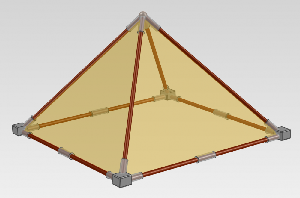
I need to develop several models of the great pyramids with different main angles. For that I need to prepare precise geometry for all the parts in IronCAD. Parts shall have connectors, therefore it is not trivial task. The ideal solution that I want is create a parametric 3d sketch. Such as following, but for 3d path: As I know, IronCAD doesn't have 3d sketch tool. Can you recommend some IronCAD's tools to create a parametric editable pyramid frame, which will allow recalculate all the geometry along the new path?
-
thank you, it works!
-
I applied the "Trim Steels by Surface Part" instrument to a couple of my steel tubes. Now I have no idea how to undo that action. I have a tube with trimmed end and there is no place where I can remove that:


-
For example, if want want easily change this length, without changing each part separately:

-
No, I'm talking about something like this behaviour, and I want this for three holes & pin at the same time.

-
I want to make a deck chair for myself, something similar to the following: For that I model the following assemble based on simple parts with cylinder holes, pins, concentric & mate constraints. As you can see, some connection nodes consists of up to 3 parts put on one axle. Once the sizes, holes and constraints were set, I cannot easily move the connection nodes and resize the parts because they are locked. What way & tools do I need to use to be able to handy edit all the part sizes and connection node places?


-
Thank you, seems currently I can imagine how to do what I need using ironCAD with user-defined parameters, patterns, linked copies, attachment points.
-
Thanks for your reply. I need to invent most optimal way to fasten disassembled constructions based on standard square tubes / profile steel corners. Therefore I need a handy tool to experiments with a various parts, need to move, rotate, re-attach them by different holes. IronCAD is a good thing for that. I also want some automatic tool for corner/plate/bracket connections. I think BRICSCAD is not suitable for my task, but anyway it is good advice. Seems there is no such the tool I want for IronCAD, but can one at least import some standard hardware connection elements library to it?

-
I need to develop bolted steel structure as esily and fast as possible. IronCAD has nice Add-ons for steel tubes and bolts - Mechanical and IronPro XT. But how can I easily use standard building corners, brackets, plates to connect my square tubes? I don't see such a tools or libraries. Does IronCAD have some way to create steel connections like the Autodesk Advance Steel? I need a convenient tool for developing and testing various variations of the steel structures. Now the most handy CAD what I found is IronCAD and I don't want to use Autodesk.


