GNÄSLUND
-
Posts
58 -
Joined
-
Last visited
Recent Profile Visitors
713 profile views


GNÄSLUND's Achievements
")
Cylinder (3/9)
17
Reputation
-
Advise on how to add triangular gusset to a pipe?
GNÄSLUND replied to Aleman15's topic in General Discussion
A triangular shape gusset can be created using an intellishape block and a chamfer. Create the block with side lengths 47" X 1 5/16 X desired thickness. Use the "dist-dist" option for the chamfer and then you can drag and snap the handles to match the length and height of the block. Then you need to position the gusset onto the pipe where you want it using the triball. If you look at exercise 1-7 at the web page below you should be able to do it https://ironcad.academy/tutorial/training-01 -
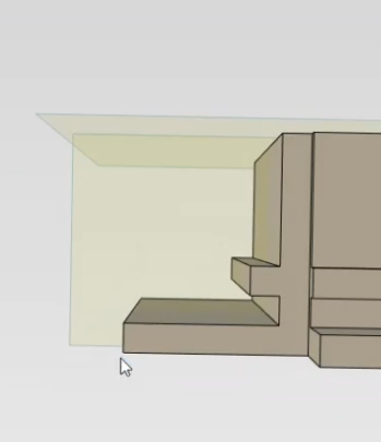
Regarding 1. I always use Ctrl+E to switch on/off hidden lines. (And after that I also adjust transparency slightly in the properties tab)
-
Adding miters to a structured frame is easily done with the "Trim/Extend" tool. https://www.ironcad.com/support/2023/IRONCAD_Help/Content/3D_Design_Environment/Part_Design_Process/Trim_Extend_Structured_Frame.htm?Highlight=trim
-
I tried a simpler sketch since I dont know how to extract that sketch you did to a standalone sketch. See video below. However there seems to be a bug, since the finished profile is not quite the same as I started with. It is missing the 45 degree part. See pictures below. IRONCAD_CustomProfile.mp4

-
I think you refer to "Add custom structured frame" in the Structured Parts toolbar I tried this earlier today and it was really easy to get going. Just create a new scene and draw a 2d sketch with the profile and add dimensions and constraints to that sketch. Save that single sketch to a new .ics Then follow this: https://www.ironcad.com/support/2023/IRONCAD_Help/Content/3D_Design_Environment/Part_Design_Process/Add_Custom_Structured_Frame.htm
-
Also you must use right-click to finish the command when you dont want to add any more views
-
Creating Hydraulic/Electrical Schematics w. CAXA
GNÄSLUND replied to GNÄSLUND's topic in General Discussion
Malcolm, your CAXA knowledge is invaluable, thanks for sharing! -
Hello, I am currently doing electrical and hydraulical schematics in another software but I am looking into using CAXA instead. Do any of you currently use CAXA for this type of work and what is your typical workflow? Here are some of the questions I have regarding schematics drawing in CAXA right now, I will add more as they arise Is it most common to draw the schematics directly in the Layout view or is there some benefit in using the model view? Is it possible to create a BOM with the components added to the drawing? How do I make the "dot" symbolizing connected wires?
-
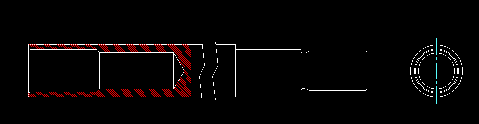
I found a solution: it is possible if the broken-out-section is created first and then the broken view after that.
- 1 reply
-
- 2
-

-

-
I have a long slender part with internal features that I want to draw using a view that has a broken view and then a broken out section in that view. Is this possible to achieve in CAXA? See example below from other CAD software
-
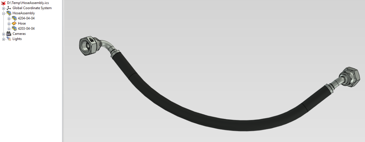
IRONCAD_Lofted_hose.mp4 A structured part with a loft gives a good approximation of a hose. The benefit is that it auto-updates when moved. The main drawback is that the length is not easily measured. Important to use ACIS when doing these kind of lofts. Parasolid seems to only be able to handle small deviations in the direction before failing. Lofted hose.ics
-
An improvement that I would like is the ability to move the endpoints of the 3d curve while maintaining tangency to the spline. Currently that is only possible for one side of the spline it seems. I have note filed a ER for that though
-
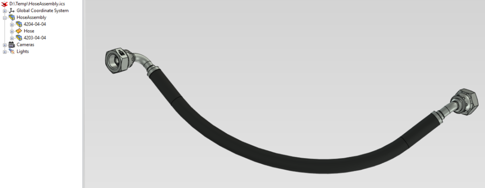
I create hydraulic hoses in a similar way. First position each end coupling on the desired spot. Then start a new part and draw a 3D-curve. First a short straight line from each coupling Then a spline between them with the tangent option. Create sweep with desired radius If I move one coupling I need to adjust the 3d-curve but that is quite quick to do.
-
I always drag-and-drop STEP-files and Parasolid-files directly into the 3d-scene in Ironcad. It is a bit annoying that this does not work for IGES-files... Is there a technical reason/limitation or can this be reconfigured to work with drag-and-drop?
-
One of the benefits with structured parts mode for this part is that the sketches can be connected to each other so that the model can be easily updated afterwards loft_structured_parts_mode.mp4