Leaderboard


Popular Content
Showing content with the highest reputation since 06/05/2019 in all areas
-
Recently I needed to create some 3D models from PDFs received from a client. These PDFs didn't include all of the dimensional information needed, so I was grateful to have at my disposal the "PDF Import" tool within CAXA (not to be confused with the "Insert PDF Underlay" tool). The "PDF Import" tool converts PDFs into CAD geometry (which is what I needed). Attached is a video demonstrating how this works. The PDF used in the video was originally created in CAXA, and the original "Layers" from the CAXA drawing were saved within the PDF. During "PDF Import" these same layers are again imported back into CAXA. Depending on what print driver (or software) created the PDF, "Layer" information may not be available. Malcolm CAXA - PDF Import.mp46 points
-
This will be obvious to some, but it won't be obvious to all, so I thought that I would mention it. After importing geometry from another CAD system, the resulting imported Body is a BREP (or dumb solid). We can use intellishapes to add and remove geometry to this Body, but we can also directly edit the faces of the existing Body. This is called "Direct Face Modelling" (DFM). The "Selection Filter" at the bottom right of the Status Bar is a really useful tool when you want to "Box Select" multiple faces at once for editing. In one of the attached videos the length of imported geometry (hydraulic cylinder) is edited by "Box Selecting" all of the faces at one end, and then "Moving" those faces. IRONCAD then adjusts the Body accordingly. In the second video a similar process is used for "Deleting" selected faces. Note the following regarding "Box Selection" within IRONCAD and CAXA DRAFT. When you create your box from "left to right", then everything that is completely enclosed by that box will be selected. However, if you create your box from "right to left", then everything that is cut by (and inside) the box will be selected. So the direction that you use when "Box Selecting" determines what is selected. Malcolm IRONCAD - Direct Face Modelling - Selection Filter and Moving Faces.mp4 IRONCAD - Direct Face Modelling - Selection Filter and Deleting Faces.mp46 points
-
Unlike other CAD software, IRONCAD is unique in that it uses both ACIS and PARASOLID geometric modelling kernels working in collaboration. For most users and applications this isn't important, but this feature provides greater versatility to IRONCAD, that isn't possible using a single kernel. For those interested in understanding the "Kernel Collaboration" within IRONCAD, attached is our own internal document. This includes a description along with practical examples of where manually switching kernels has solved real world modelling problems. Also attached is a video of our most recent example. This involved importing and converting of a SKETCHUP Faceted Model (also attached), followed by displaying with "Real Projection" within CAXA DRAFT. This particular example required using both ACIS and PARASOLID kernels to achieve the desired end result. Other users should feel free to add other examples here also. Malcolm IRONCAD - Dual Kernels - Facet Models (Real Projection).mp4 IRONCAD - Dual Geometric Modelling Kernels - 20230330.pdf AXION MSR 8300-8309 EMERGENCY SHOWER AND EYE WASH.skp5 points
-
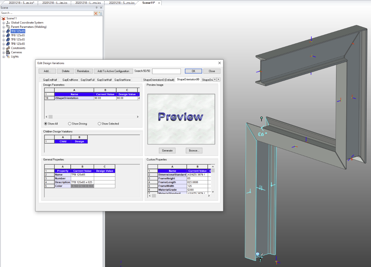
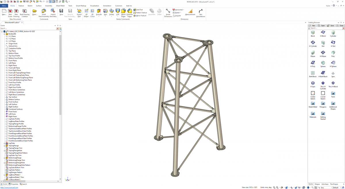
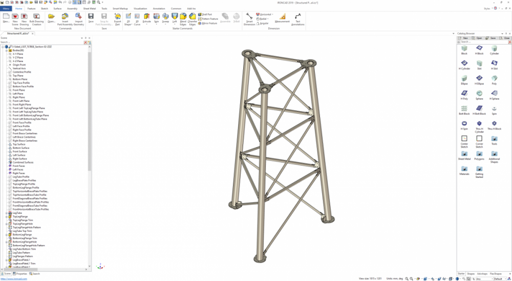
Regarding question 2. Attached is a video demonstrating how to provide "Control" over the position of the Vertical Frame Members. This method uses 2D Sketches, where the position of the Vertical Lines (Paths) can be controlled independently using Sketch Shape Handles (and unlocked dimensions). If the Sketch Dimensions are "Locked", these positions can also be controlled using Parameter expressions, so that they follow any size changes made to the top and bottom Frame Members. Also attached is a video demonstrating what Cary is suggesting, regarding adding vertical 3D Curves for these Vertical Members. This is a good solution if you always want these Vertical Members locked to the referenced geometry of the Top and Bottom Members. Malcolm STRUCTURED FRAME - Positioning Vertical Members with 3D Curves.mp4 STRUCTURED FRAME - Positioning Vertical Members with 2D Sketches.mp45 points
-
Within the "Structured Parts" tab of the Ribbon Bar in IRONCAD 2023 is a panel named "Structured Frames". This was previously named "Steel Frame" and is similar to "Weldments" within SOLIDWORKS. Structured Frame "Features" are inserted into Structured Parts, and within these "Features" are "Bodies" (Frame Members). The purpose of this post is to make users aware of the influence Structured Frames have on the Bill of Materials (BOM). Normally, the BOM references the "Part Level Properties" of a Part or the "Assembly Level Properties" of an Assembly. As soon as a "Structured Frame Feature" is inserted into a Structured Part, the BOM stops referencing the "Part Level Properties" of that Parent Part, and instead starts referencing the "Body Level Properties" of the Frame Members. As a result, the Parent Structured Part is no longer treated as a Part (or Assembly), but as an invisible Construction Object or Container (for lack of a better word). In the attached video I have tried to demonstrate this. Page 3 of the attached reference document also covers this. Malcolm Structured Frames - Bodies (Members) Displayed in BOM.mp4 IRONCAD - Structured Frames - 20230312.pdf5 points
-
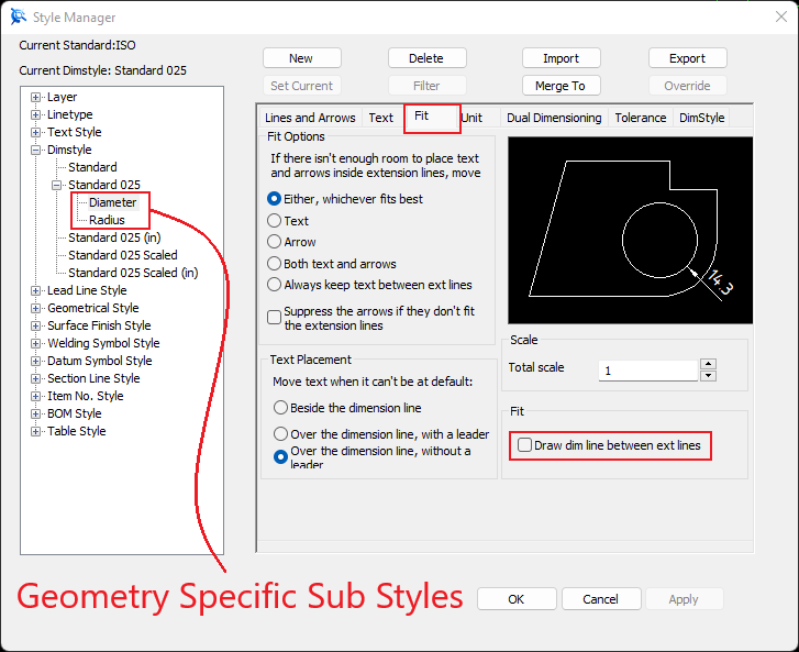
Within the Dimension Styles of CAXA DRAFT it's possible to create "Dimension Type Specific Sub Styles". In the attached video I have created a sub style for Diameter and another sub style for Radius. In each of these sub styles I've turned off the "Dimension Line Between Extension Lines". When the parent Dimension Style (Standard 025) is set to current, those sub styles within it will be applied to their specific geometry. This eliminates the need for manually toggling off the Dimension Line afterwards, when dimensioning small circles and arcs. Malcolm CAXA DRAFT - Dimension Styles - Geometry Specific Sub Styles.mp4
 5 points
 -
When deleting individual blends from a long list of selected edges, it can be difficult to identify the desired edge(s) within the list. The attached video demonstrates that while editing a Blend Feature, when the edge is selected in the Scene, it is then highlighted in the Blend Properties Browser, from which it can then be deleted. Malcolm Blends - Selecting Edges for Removal.mp45 points
-
I would like to especially acknowledge the great job that IC's support team and their Channel Partners provide. Nothing is too trivial or beneath them to help when you need it. Even late into their Sunday evening doesn't deter these guys from helping you out when you are stuck with a problem. To my mind, this makes using IronCad even more a pleasure. Also, while I am at it, the willing help from those IC users who take time out of their busy schedule to show us tricks, tips and gladly give advice is also so much appreciated - people like my fellow Countryman, Malcolm Crowe for example. This makes IronCad and its community quite special and I am glad I settled on this product in preference to all the other competitors in this 3D Cad market. All the best for the Festive Season and years beyond. And again, THANK YOU Harley P.S. ( yes I know - I was taught at school never to start a sentence with an 'And' but stuff it - why not )5 points
-
Hi Kim, IRONCAD (CAXA) 2024 introduced the capability to have multiple "Papers" within a single tab. This was introduced specifically with the "Model" tab in mind (like the example in your image), but it is also applicable to the "Layout" tabs as well. Attached is a video demonstrating the principle of how this works. Regarding what file format to use in CAXA, we normally use CAXA's *.exb file format. We only save as *.dwg when we need to collaborate with other CAD software (like BRICSCAD that we also use). This might not be 100% correct, but I've noticed that when *.dwg files are used (instead of *.exb), then the dimensions applied to Generated Views within CAXA are not associative. That is, if the 3D Model changes and the Generated View updates, then the dimensions in CAXA don't follow as they do for *.exb files. It's more efficient to annotate drawings of IRONCAD Scenes within CAXA (with full access to 3D properties as well), rather than externally referencing into other software for this purpose. However, when you need to incorporate associated Generated Views from CAXA within 2D Models of other CAD software (like AUTOCAD, BRICSCAD, MICROSTATION, etc.) then externally referencing *.dwg files from CAXA is a good option to have. Malcolm CAXA - Multiple Papers within Model Space.mp44 points
-
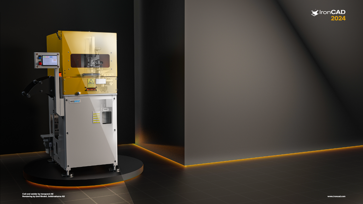
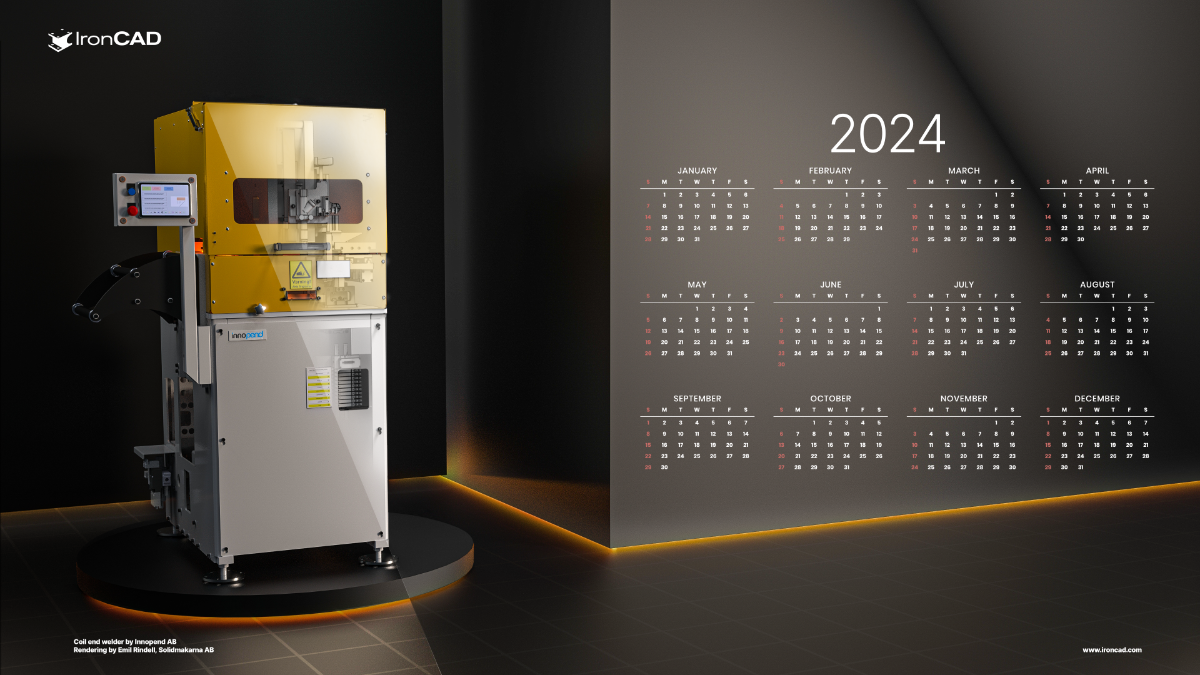
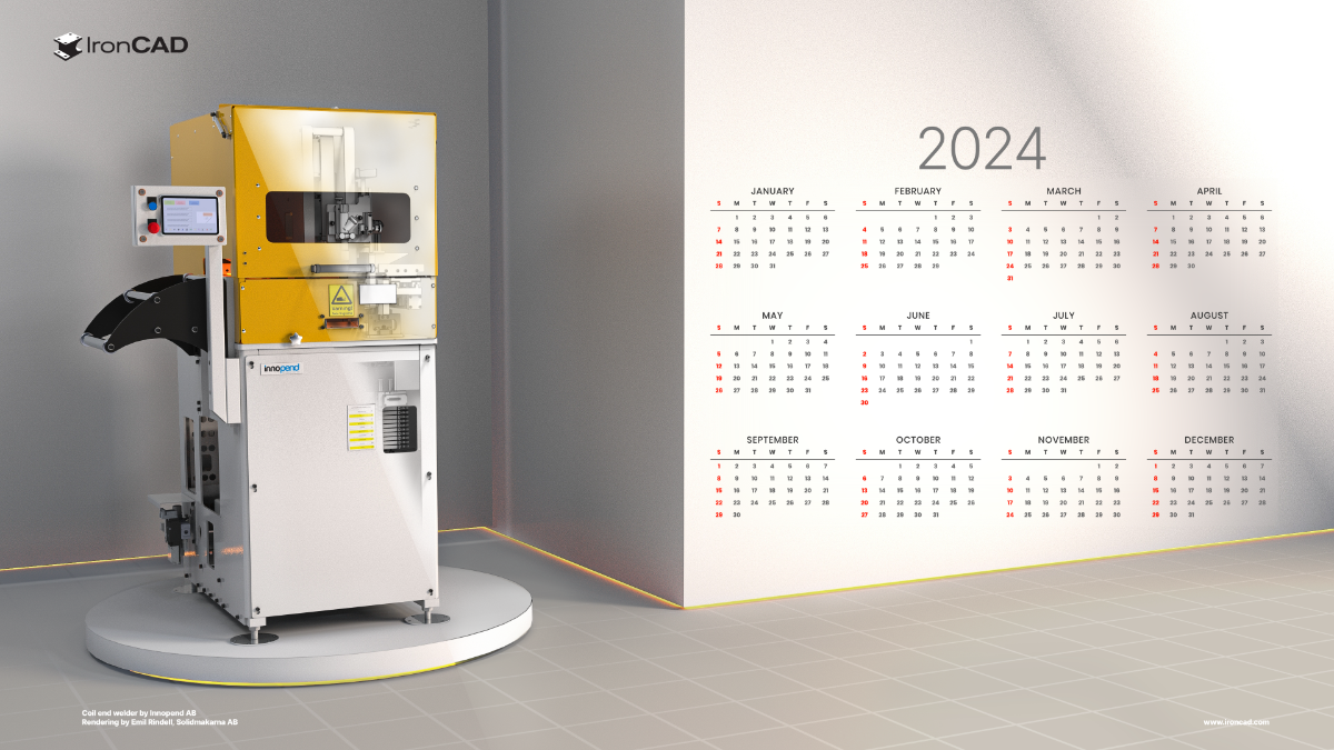
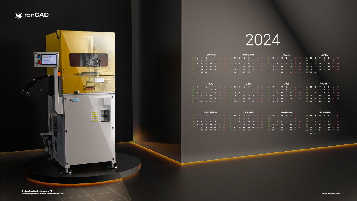
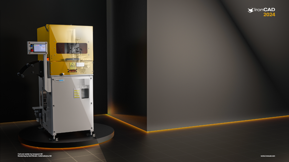
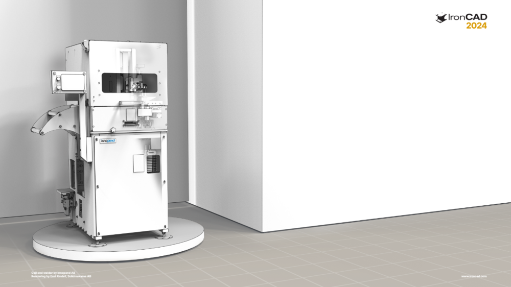
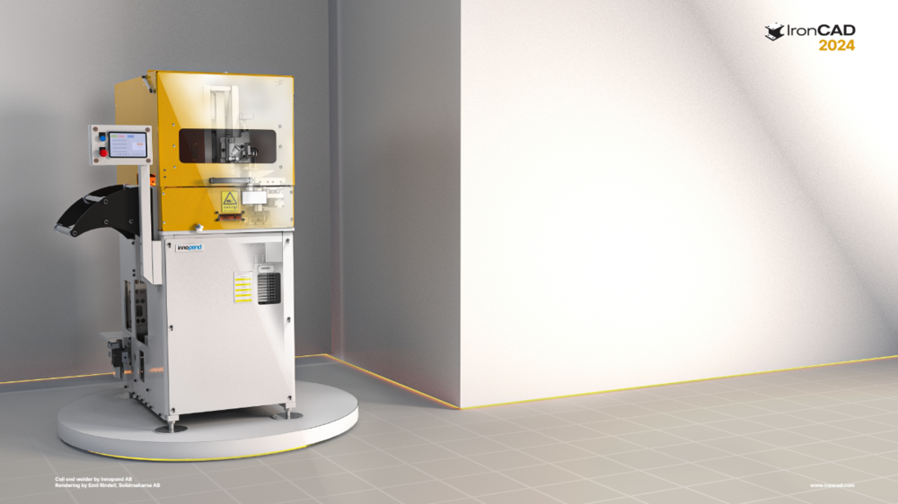
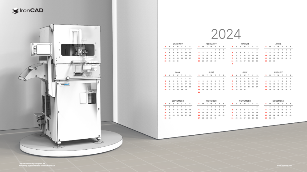
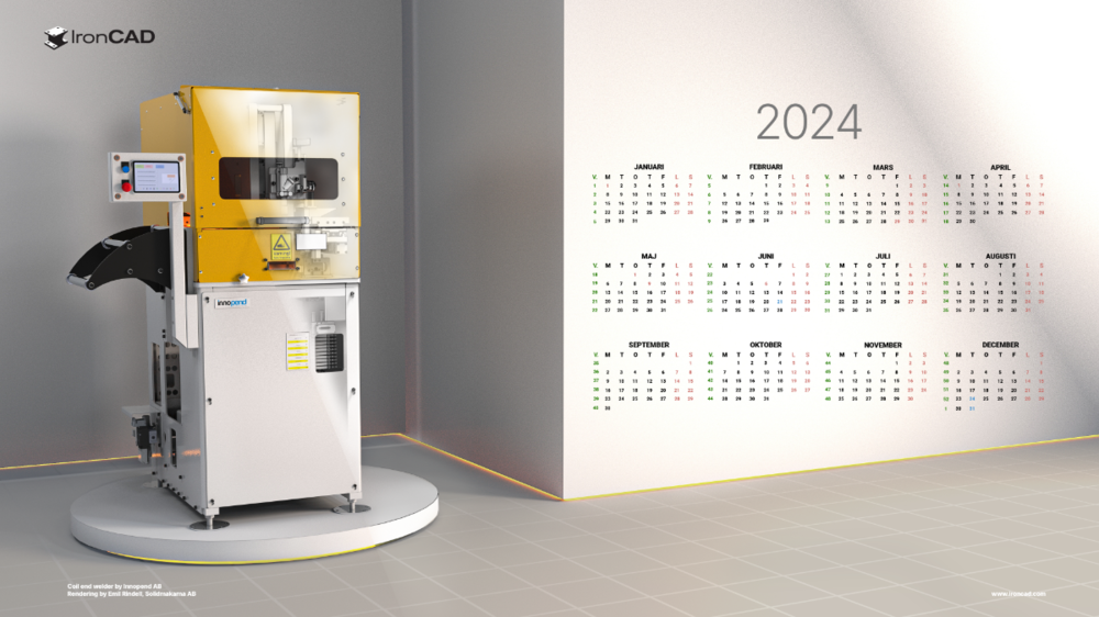
Hi all, Like the past years I decided to make some wallpapers with v2024. Model is a Coil End Welder constructed by the IRONCAD user Lennart Freidlitz at Innopend Teknikpartner AB. Hope you like it! Happy holidays IC_2024_BLACK_4k.png (10,8 mb) IC_2024_CAD_4k.png (3,5 mb) IC_2024_WHITE_4k.png (12,1 mb) English Calender Black (11,3 mb) English Calender White (10,6 mb) English Calender (3,8 mb) Swedish Calender Black (11,0 mb) Swedish Calender White (12,2 mb) Swedish Calender (3,8 mb)


 4 points
 -
Hi tgjang, I just used that old example because I knew it had many Sectioning Configurations already setup in it; but I don't consider that model to be complex compared to other work we do. For that particular project we needed to create a 3D model of an existing Multi-Storey Building (over 100 years old), so that we could then add various new Structural Elements for Earthquake Strengthening purposes. So, it doesn't include all of the details (such as steel reinforcement and connection details) that would have been needed for constructing the original building. We only needed to add details for what was to be added for strengthening. If you're curious regarding the types of structural drawings produced in CAXA from this 3D model have a look at the attached PDFs. Malcolm W140507c-S11-S19-BC1 Plan Sections.pdf W140507c-S21-S32-BC1 Southern Sections.pdf W140507c-S41-S44-BC1 Western Sections.pdf W140507c-S51-S60-BC1 Strengthening Details and Pile Cap.pdf4 points
-
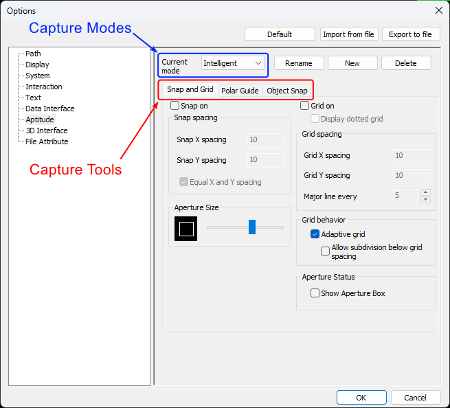
CAXA provides some really helpful tools to assist with selecting and creating geometry. The attached video and document provide an overview of these "Capture Tools" along with the associated "Capture Modes". When editing "Capture Tool" options it's important to be aware that these changes are only applied to the currently selected "Capture Mode". Malcolm CAXA - Capture Tools and Modes.mp4 IRONCAD DRAFT - Options - Aptitude (Capture Modes) - 20230905.pdf
 4 points
 -
This video specifically relates to the "Parallel Capture Tool". This is enabled when using the "Guide Capture Mode". Malcolm CAXA - Parallel Capture Tool within Guide Mode.mp44 points
-
Attached is a video demonstrating how to combine 2D geometry (located in a Block) with 3D geometry (located in a Generated View) within "Model Space". And to then display this combined geometry within "Layout Space" at different view scales using "Viewports". This includes how to use the "Align" tool to perfectly position the 3D geometry on top of the 2D geometry, and how to "Pan" (position) the model within the Viewports. This is a good example of when to "Generate Views" within "Model Space" (instead of directly within "Layout Space). Malcolm CAXA - Model Space - Combining 2D and 3D Geometry.mp44 points
-
Because we create a lot of Parametric Parts, we try to be consistent in how we construct and manage Parameter Names (regardless of who is creating the model). The naming conventions that we've used over the years have varied, but for those who are interested attached is our current internal document defining how our Parameter Names are to be constructed. Malcolm IRONCAD - Parameters - Name Construction - 20230708.pdf
 4 points
 -
So to share my experience with IronCad for architecture. The creation process is very nice and fun as we all know. It becomes more tricky when you need the production plans / drawings. So first create your own Styles and Layers! For Line thickness and all hatch. You can save them (IC saves them in the sheet so copy the sheets) and they are ready to use, quite tricky as a start but there is a benefit in the production. PS: Here a nice tutorial would help. So my tricks: 1. Never change the name of the main file, save backups with numbers… So the drawings are always corresponding with the file. (make a backup every day!) 2. in progress the architecture details change all the time …so you must make the same plan many times. Therefore, the ViewManager in IC Mechanical is perfect. With the view Manager you can save any view for each drawing. So you can develop the building and easily update every drawing, no matter which floor or detail. Easily change between the drawings. And then something new for IC: Maurizio of IC Mechanical helps you immediately. If you find a bug or a problem, next day you get an updated software! WOW! Thank you Maurizio! So finally I am relatively happy to make architecture with IC the bugs or ERs in drawing section are known. Hopefully the come. But without the view manager I guess it would be hard. So Mechanical is every doller worth. See the movie! View Manager.wmv4 points
-
If you need a free STEP Viewer for checking the 3D Models exported from IRONCAD, then the OPEN DESIGN ALLIANCE (ODA) recently released their free "Open STEP Viewer". This works in a very similar way to their "Open IFC Viewer" (for viewing BIM models). Attached is a video that I created for a client demonstrating some of the functionality within this STEP Viewer. Open STEP Viewer Open IFC Viewer Malcolm OpenSTEPViewer - Basic Demonstration.mp44 points
-
For users needing "Annotative Blocks" that scale with the "Paper Scale", there are 3 types of “Annotative Blocks” in CAXA DRAFT. 1. Drawing Frames 2. Title Blocks 3. Paratables The name “Paratable” is a bit unfortunate, as this tool doesn’t need to be limited to Tables. It can in fact be used for creating any type of “Annotative Block” (consisting of attributes, line elements, text, etc), that needs to scale with the “Paper Scale”. Attached is our in-house document regarding "Paratables", along with a demonstration video. Malcolm CAXA - Paratables (Annotatibe Blocks).mp4 IRONCAD DRAFT - Paratables (Annotative Blocks) - 20230522.pdf4 points
-
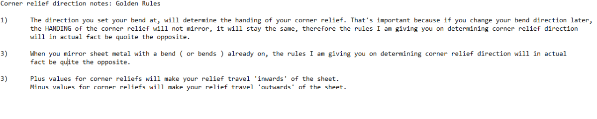
NOTE! The earlier video I made, had a major mistake. This has now been corrected ( noted May 22 20:24 GMT ) Here is a tip for those of you wanting to know which bend is affected when making closed reliefs. NOTE! The text 'Left' and 'Right' is only shown here to demonstrate which side is affected. Obviously you'd never put these texts on your actual model, In addition, Malcolm has kindly lent me his handy ICS file which shows bend directions and 'look-at faces' to share with you. Sheet metal bend reliefs left or right.mp4 Sheet metal bend reliefs left or right part 2.mp4 Sheet Metal - Bend Corner Reliefs - Look At Face - 20230522.ics
 4 points
 -
Many users will be familiar with creating "Patterns" using the TriBall or perhaps the "Pattern Feature" tool. But another option is using "Sketch Patterns" within 2D Sketches. This is especially useful when used with the "Structured Frame" tool. Attached are a couple of videos demonstrating what's possible. One example uses Parameter Expressions to calculate an "Equal Distance" between Patterned Objects. Whereas the other example uses Parameter Expressions to calculate an "Equal Gap" between Patterned Objects. Malcolm Structured Frames - Sketch Pattern - Equal DistanceX.mp4 Structured Frames - Sketch Pattern - Equal GapX.mp44 points
-
My original Engineering and Operational Management background was within high-speed Manufacturing Operations (24 hours per day, 6 days per week, and speeds up to 1,000 parts per minute). As a result, I have a very good understanding of the ingredients necessary to maximize “Productivity”. When consulting for new manufacturing clients, one of the typical questions that senior management ask is what new Plant and Machinery they need to invest in to “Increase Productivity”. More often than not, the missing ingredient that they need to invest in is “Training (Learning)” of their staff. The same is true regarding CAD productivity. The CAD software that you use is only one of the ingredients. The value of investing in expensive CAD software, add-ons, or upgrades, is greatly reduced if you don’t invest in learning how to use the capabilities they offer. You may as well have invested in far less expensive software better matched to your level of understanding and usage. So, if you've chosen to be in the design business, chosen to invest in the Hardware and the Software required, then “Choose to Invest in Training (Learning)” as well. You'll become a lot more "Productive" as a result. Malcolm
 4 points
 -
Within the "Structured Parts" tab of the Ribbon Bar in IRONCAD 2023, within the "Structured Frame" panel, a new tool has been added named "Add Custom Structured Frame". This newly added tool enables users to add their own Custom Shapes based on 2D Sketches and Size Data (which can be entered directly or imported from an Excel Spreadsheet). In the attached video I have tried to demonstrate the process involved. Pages 4 - 6 of the attached reference document also covers this. Malcolm Structured Frames - Adding Custom Shapes and Sizing Data.mp4 IRONCAD - Structured Frames - 20230312.pdf4 points
-
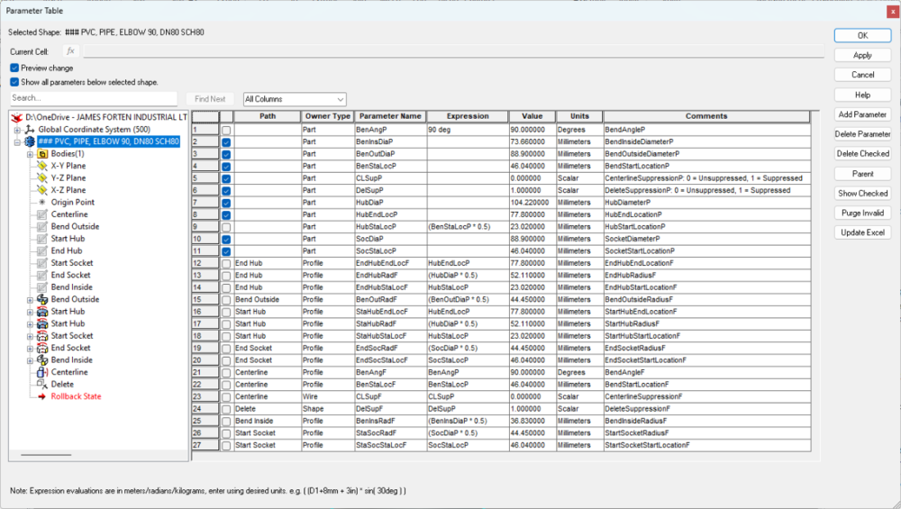
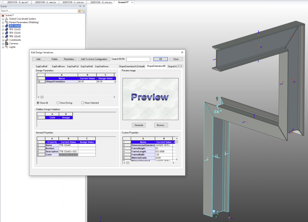
IRONCAD has some great tools for manually modifying the geometry of Shapes, but it also has some very useful tools for modifying geometry using Parameters as well. These tools can be summarized as follows: - Parameter Table: For creating different types of Parameters (Angle, Distance, Scalar and Suppression) - Design Variations: For simple user input (toggling) of Parameter Values into the Parameter Table - Attachment Points: For transferring Parameter Values between Shapes, Parts and Assemblies The attached video demonstrates a little of what is possible with some Parametric Shapes (Structural Steel). Malcolm Parameters and Design Variations and Attachment Points - Shapes.mp4
 4 points
 -
By default, all Parts and Assemblies within the 3D Scene should have "Include in BOM" selected (within the Properties Browser), as you normally want these to be included in a BOM. However, there are some exceptions, such as Construction Items (like Layout Sketches) and Reference Parts (like existing Parts or a Building etc...). For these items you would deselect "Include in BOM" when you create them. However, if the Referenced Parts have other 2D drawings referencing them (which might be the case with externally linked parts), DO NOT deselect "Include in BOM" for these Items, as doing so will affect those other drawings as well. In the attached video I demonstrate some options for excluding Referenced Items from the BOM in your 2D Drawing. This is specifically regarding CAXA DRAFT, but most of what is demonstrated is applicable to IRONCAD DRAWING (ICD) as well. Option 1: Within the CAXA BOM deselect the "Display" option. Option 2: Within the 3D Scene create a "Configuration" in which the Referenced Parts are "Suppressed". Then set the BOM to reference that specific "Configuration" while the Generated Views reference a different "Configuration". Option 3: Within the 3D Scene, place any "Reference Parts" within a specific "Referenced Parts" Assembly. Then in the Properties Browser of that Assembly select "Treat as Part", and then deselect "Include in BOM". Option 4: This is a variation of Option 3 above. Within the 3D Scene, place any "Reference Parts" within a specific "Referenced Parts" Assembly. Then in the Properties Browser of that Assembly select "Treat as Part", and leave "Include in BOM" selected. Then in the BOM of CAXA deselect "Display" for that one Item. This option allows the "Item Number" tool to be used for labelling these Referenced Parts within the drawing as well, without being listed in the BOM. Malcolm CAXA - BOM - Excluding Referenced Items.mp44 points
-
Hi Kim, As you have already said, IRONCAD accesses files from many different locations, including "Program Files", "User AppData" and "User Documents". None of these locations are helpful in a multi-user working environment, where its advantageous to share common configuration and data files. Therefore, wherever possible we direct IRONCAD and CAXA to a Custom Shared Folder Structure located on SharePoint. This includes folders for "copies" of customized AppData files that need to be copied to "Program Files" and "User AppData" of each local computer. I've just completed updating our inhouse documentation regarding these "Files and Paths", and I've attached these here for the benefit of other users. Malcolm IRONCAD DRAFT - Files and Paths - 20230729.pdf IRONCAD - Files and Paths - 20230729.pdf4 points
-
Within the 3D Scene, users have the ability to create "Local Coordinate Systems" alongside the default "World Coordinate System". Within CAXA DRAFT there is a similar capability, where users can create "User Coordinate Systems" alongside the default "World Coordinate System". Attached is a video demonstrating some examples of how "User Coordinate Systems" can be used, for creating geometry and annotations aligned to other geometry. Malcolm CAXA - User Coordinate Systems (UCS).mp44 points
-
Great video Malcolm! Expanding on this using the profile handles is another method. Video below will explain the process. 2023-01-18-13-36-12.mp44 points
-
Hi Gigi, I downloaded your ICS file, but I was unable to open it. So, based on what you've described above along with your previous post, I've tried to demonstrate in the attached video what I think you're trying to achieve. To solve these types of problems we typically use "Layout Sketches", so that is what I'm demonstrating here. My apologies if I have completely misunderstood what you're trying to achieve, but perhaps this will still give you some other ideas that you can apply elsewhere. Malcolm Sheet Metal Layout Sketch - 20230117.mp4 Sheet Metal Layout Sketch - 20230117.ics4 points
-
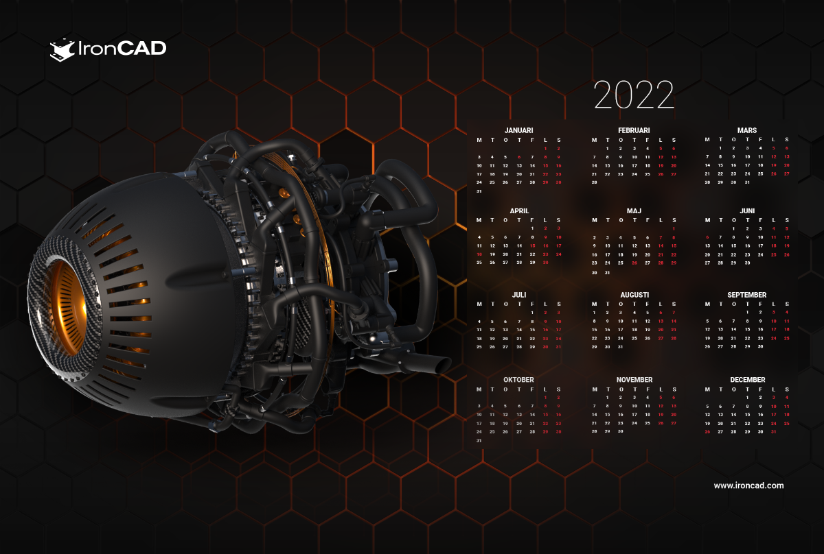
Hi all, I decided to create a calender wallpaper for 2022. I made a facelift on the turbine engine. Feel free to use it and hope you guys like it. Also attatched a calender for all the swedish users ofc:)

 4 points
 -
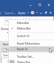
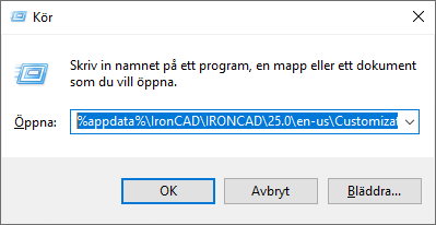
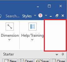
With version 2023 there's a new option to do this more easily. Right click in the top right "empty" area of the UI and choose Reset UI. This will remove those XML files automatically when you close IRONCAD. The XML files are restored when you run and then close IRONCAD again the next time (saving the state of the UI when the last open file is closed). Here is another way to find the path to the XML files, using a "general directory shortcut" that works for anyone exactly as it is (no need of the exact path). Just copy and paste into the address bar of the File Explorer or use the Run command: %appdata%\IronCAD\IRONCAD\25.0\en-us\Customization Other useful directory shortcuts; %localappdata%\IronCAD\IRONCAD\ - where the Cosmetic Thread data table and Sheet Metal Stock and Tool table files are stored but also the XML files that stores the shortcut keys (which you can actually manually manage (restore with a new version), if you know how to read and manage XML files, but please handle these files with care). %public%\Documents\ - where the IC Mech add-on stores tables and other data for the standard components. This could also be a useful place to store IRONCAD-files, if you are more than one user sharing the same computer. It can also be a "general place" to store files like IRONCAD catalogs (*.icc), backup copies of drawing templates (*.icd or *.exb), license documentation (*.pdf) and other useful stuff that doesn't have to be unique to a certain version. Unless you simply want to use your default %userprofile%\Documents\ folder
 4 points
 -
Cheers to all the IronCAD users world-wide who meet here on the Community. I especially appreciate those of you who help each other solve issues, you make my job even easier. Here's to a prosperous 2023 for everyone! IronKevin4 points
-
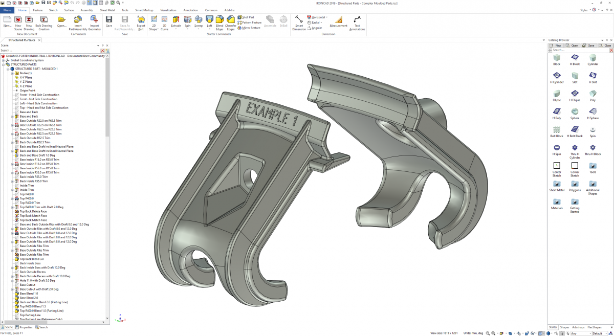
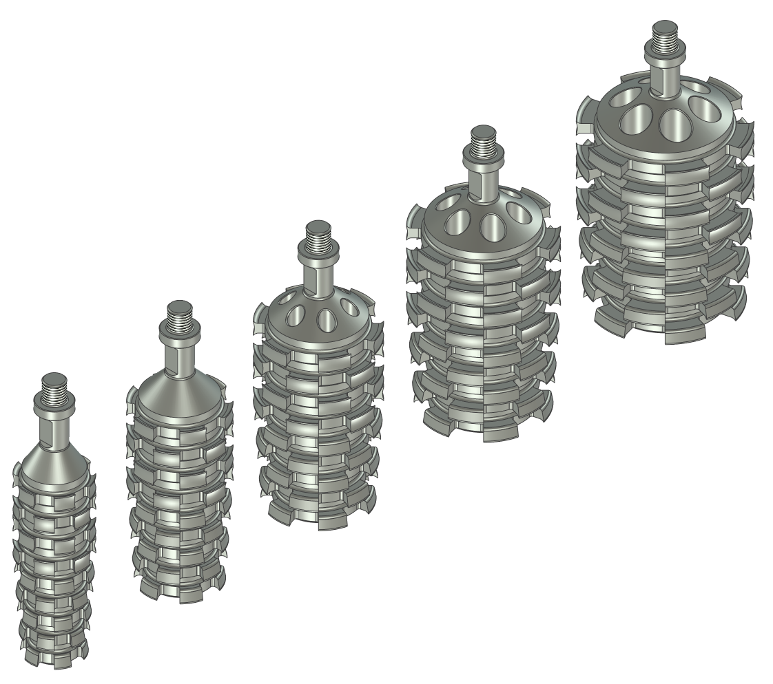
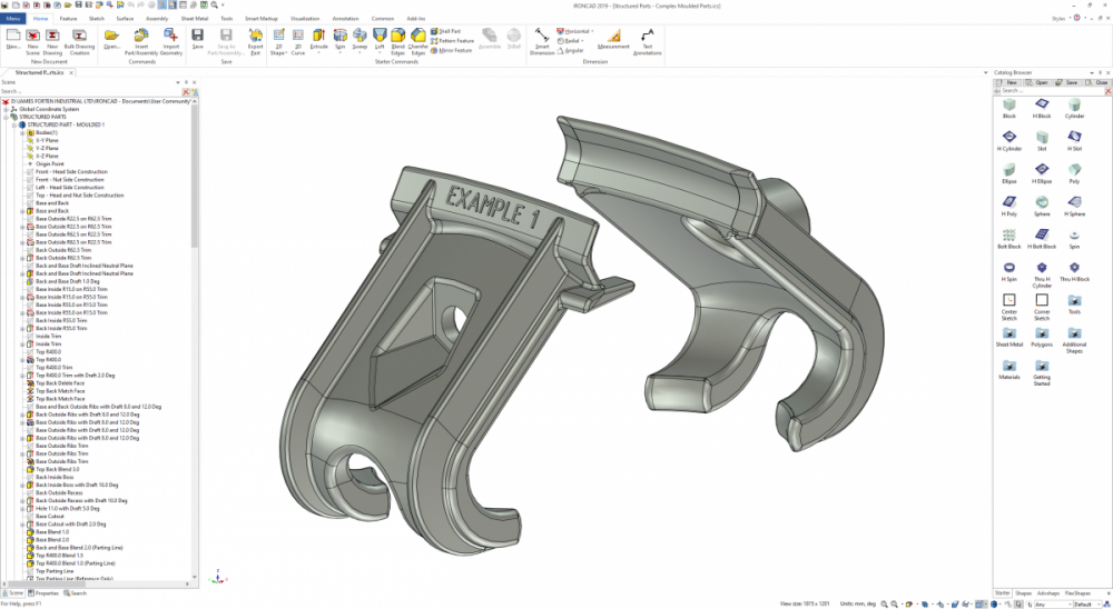
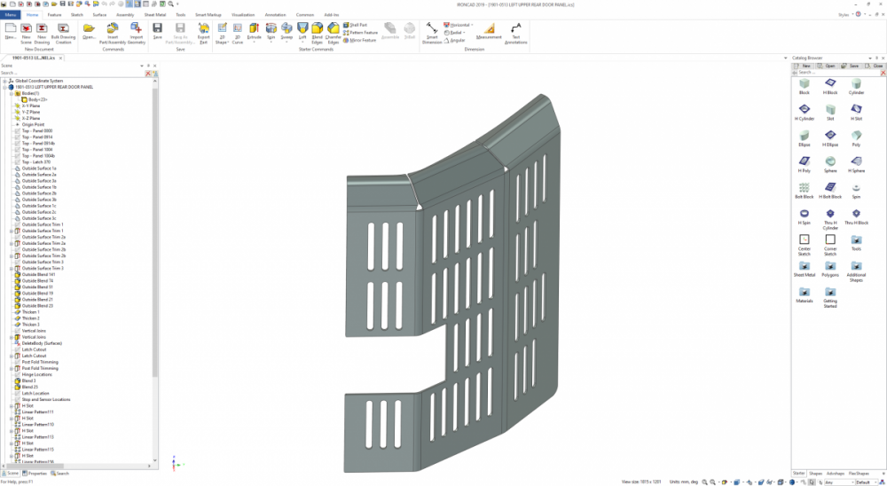
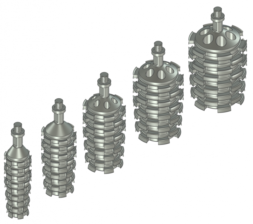
One of the key advantages of IRONCAD is that it offers users the option of working in either "Innovative" or "Structured" part modes. Personally speaking, "Innovative" is my preference for simple 3D models, as they are fast to create and edit. However, "Structured" is my preference for complex 3D models (and 2D layout sketches). These require more thought and take longer to construct; however, these can be easier and faster to edit (changing parameters) than "Innovative" parts and assemblies. Attached are some examples of "Structured" parts and assemblies. 1. Complex Moulded Parts (using multiple steps to construct the necessary features and draft angles) 2. Complex Sheet Metal Parts (using multiple construction elements within the part) 3. Parametric Part Families (family of parts based off common structured parametric part) 4. Parametric Assemblies (multiple associated "bodies" - that can be externally linked also) When you need to use construction elements (such as sketches, 3D curves, surfaces, and reference bodies), to help construct a complex part; then "Structured" mode keeps these construction elements within the part itself (and maintains the associations between those elements). Malcolm Structured Parts - Multi-Bodied Assemblies.mp4
 4 points
 -
Update #2: Doh! Installing a correct and current Bootcamp driver for the Radeon graphics card does wonders! Performance is now fine, screen content can be moved and rotated quickly, even with large assemblies. That's good news :-) Bernd4 points
-
2021-09-17-16-43-19.mp4 Here is a method using the Constant Face Blend versus the edge blend. Cary4 points
-
This may be obvious to everyone, but I just realized you can do this which is very helpful. When I create exploded views that require the endpoint of the 3D line segment to fall in an area that would generally need a node to snap to I now use this method. The video will show what I mean, but you have to click the middle of the triball at the end and then not move the mouse and click again for it to work. Hopefully someone out there finds it helpful. -Spencer 2021-07-23 13-54-50.mp44 points
-
If you have a 2D Sketch within an Intellishape that you would like to copy and use elsewhere, simply select the 2D Sketch (within the Intellishape) in the Scene Browser. While holding down the left mouse button drag it into a catalog and release; then from the catalog drag it back into the scene. No special tools or add-ons required. See the attached video. Malcolm IRONCAD - 2D Sketches - Copying from Intellishape.mp44 points
-
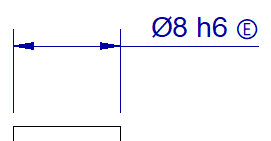
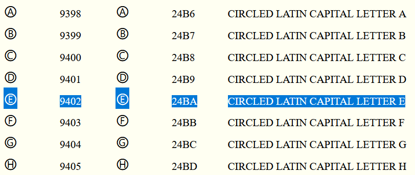
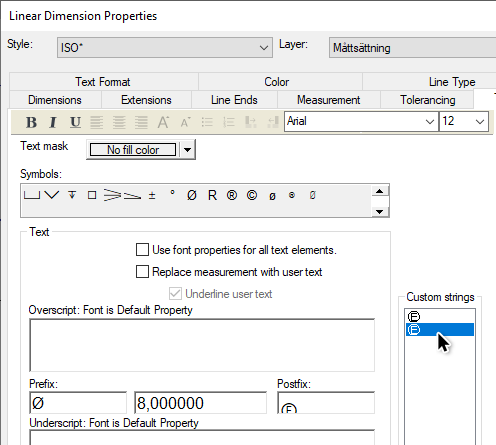
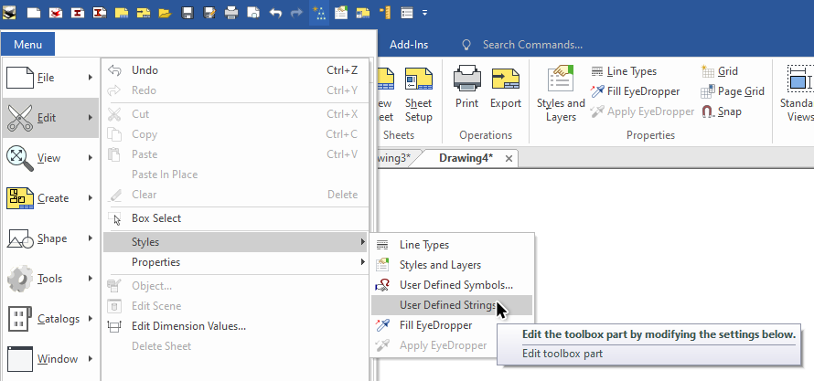
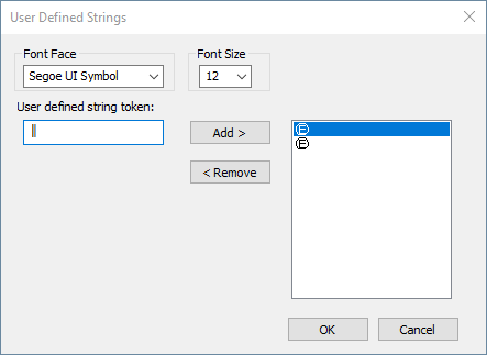
To place an Envelope Requirement on a diameter or linear dimension with an ISO-tolerance, you can use a certain shortcut key sequence to create the symbol as a postfix of the dimension text. Depending on your localization of Windows (language) there might be two optional ways of doing this in IRONCAD. One of these two (or both) ways should be working; Go to the postfix and type 24BA. Select the text string and click [Alt]+[x] and it will convert the "24BA" text to a circled E. Go to the postfix and hold down the [Alt] key while typing [9] [4] [0] [2] "in sequence" on the numerical key pad and a circled E will be created. See this list for a list of other fonts similar http://www.alanwood.net/unicode/enclosed_alphanumerics.html Also remember to place all special symbols in the Custom Strings library, for easy reuse whenever needed! Go to Menu > Edit > Styles > User Defined Strings Type the character shortcut key command (or whatever text string you'd like) and use the Add > button to add it to the list of custom text strings. For me, I had to change to the font named Segoe UI Symbol first and use the the [Alt] key while typing [9] [4] [0] [2] num pad function, because using the Arial font just showed me the wrong symbol.
 4 points
 -
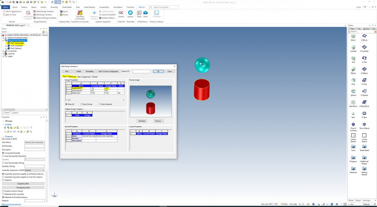
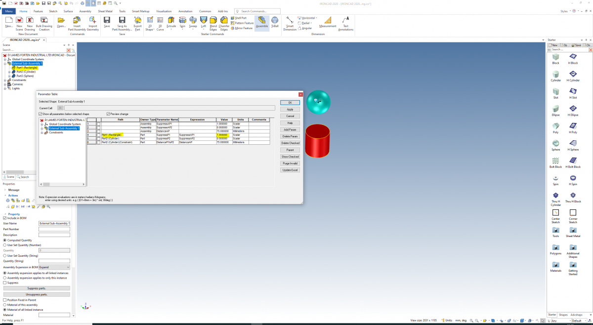
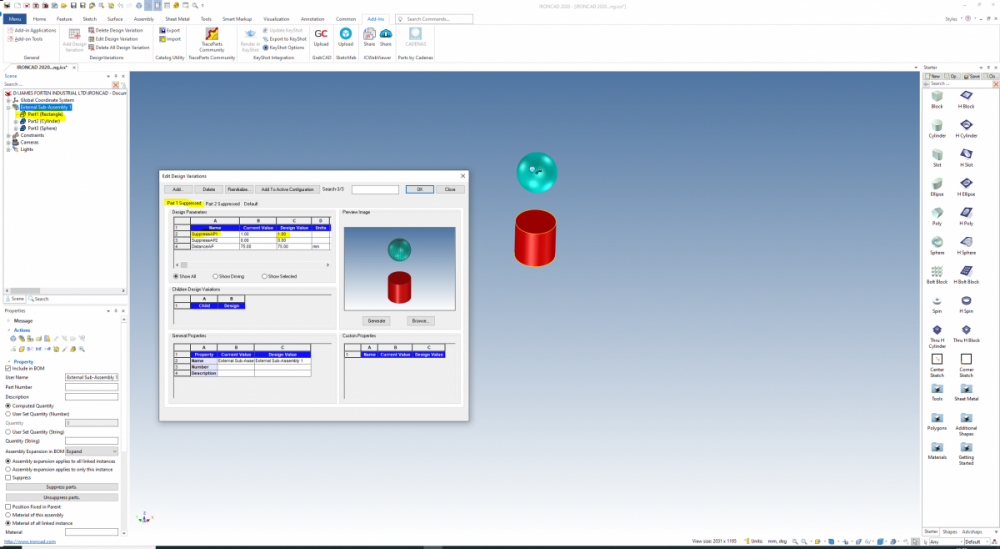
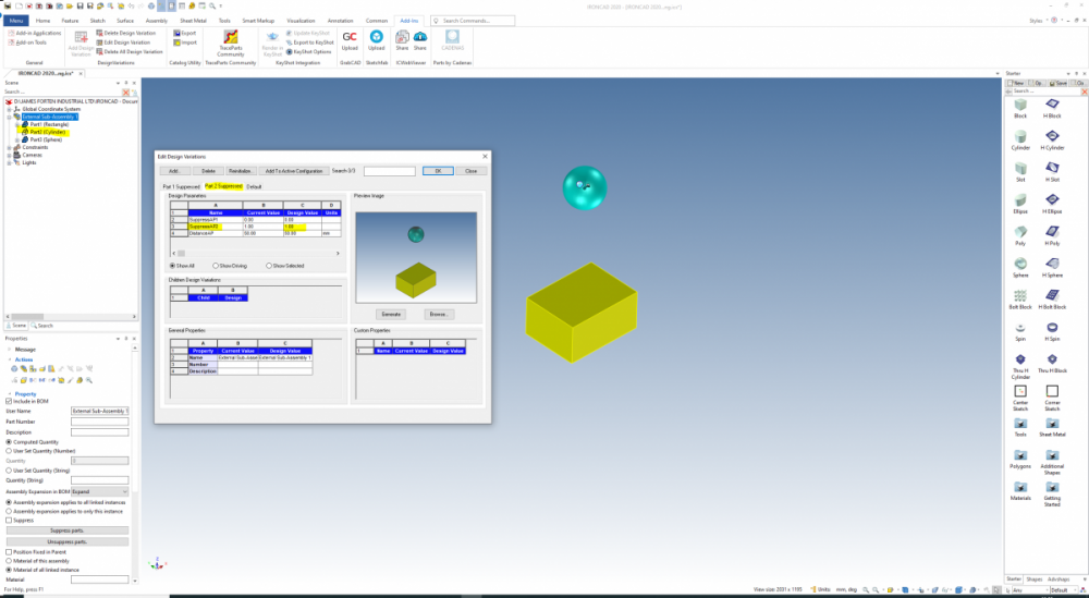
The easy way to suppress and unsuppress an assembly, part or feature is to simply right-click on it and select "Suppress" to toggle it on or off. These suppressions are stored with "Configurations", but they aren't stored with "Design Variations". When referencing externally linked assemblies and parts, there are occasions where it is beneficial to store these suppressions within "Design Variations". To do this you need to first create "Suppression Parameters" that can be toggled on and off with values of "1" and "0". Attached are images and a video demonstrating this. In a separate post "Configurations - Linking to External Design Variations" I'll demonstrate occasions where these Suppression Parameters are beneficial. Malcolm Parameters - Suppressing and Unsuppressing.mp4 IRONCAD 2020 - Parameters - Suppressing and Unsuppressing.ics
 4 points
 -
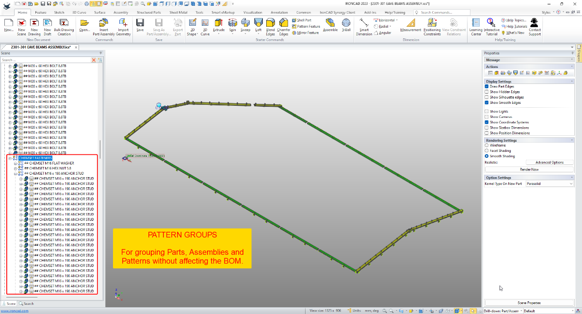
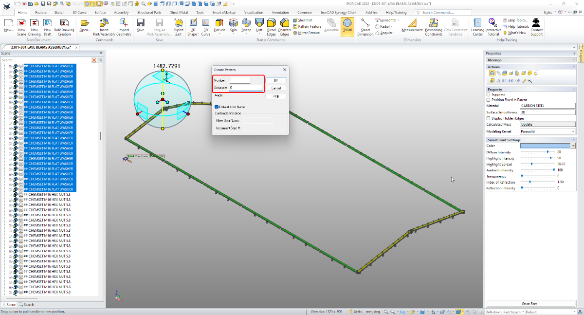
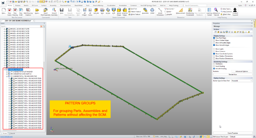
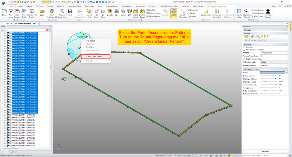
I use the term "Pattern Group" as a Group (of Parts, Assemblies or Patterns) created using the "Linear Pattern" tool of the TriBall; where the pattern number has been set to "1" and the distance to "0" (zero). "Pattern Groups" are extremely useful for simplifying the assembly structure within the Scene Browser, without affecting the BOM (which would be affected if an Assembly was used). The attached video demonstrates how this can be used for grouping hundreds of fasteners to greatly simplify the assembly structure, without affecting the BOM in the associated 2D Drawing. It also includes placing Pattern Groups within other Pattern Groups. Malcolm IRONCAD - Pattern Groups - Alternative to Assemblies and Groups.mp4
 3 points
 -
Hi tgjang, In the particular example above (and in the attached video) all of the Structural Steel components were modelled using Innovative Mode. However, the referenced Concrete Foundation and Tilt Slab Walls were modelled using Structured Mode. We always use Structured Mode for creating our layouts for referencing, as there will be a number of 2D Sketches (including the Architects Grid) that we need to be fully associated. And in this instance, the Concrete Foundation and Walls are separate "Bodies" within this Reference Layout. Our projects are seldom created using 100% Innovative Mode or Structured Mode, as both modes have their advantages (depending on the application). For example, for Structural Engineers involved during the design stage, using Structured Frames (rather than Innovative Parts) is actually more advantageous for them. During stress analysis calculations they work with Wireframe Models, to which they apply "Shape Profiles". The process is very similar to the process of creating Structured Frames, so it's a concept that is familiar to them. When the "Design Stage" is complete their basic "Structured Frame" can be added to by others (which will include Innovative Parts). So, whenever you're presenting IRONCAD as an alternative to SOLIDWORKS, INVENTOR etc..., I always recommend focusing primarily on IRONCAD's versatility (rather than ease of use, or Innovative Mode, or the TriBall, Catalogs, etc...), where IRONCAD users have the freedom to choose the modelling mode best suited for the application. The shapes required for Structural Engineering applications are very basic, so there is no benefit in having dual kernels for these. However, if you're doing Factory Layouts where you need to insert models from other sources (including facetted models which are common in architectural applications), then in my own personal experience the dual kernels have been beneficial. BRICSCAD BIM is truly versatile software as well, but in different areas to IRONCAD (although they do overlap). BRICSCAD BIM is specifically tailored for AEC (Architectural, Engineering and Construction) applications, and includes amazing Point Cloud and Civil Engineering tools as well (along with 3D modelling and 2D drafting capabilities that would surprise many IRONCAD users). If your client needs to create BIM models or collaborate with BIM models from others (whether IFC or REVIT), then BRICSCAD BIM is the way to go. Note that, BRICSCAD BIM can import 3D models created by other software (including IRONCAD) and automatically add the BIM data needed to turn it into a BIM model. That is something that we've done. So, your client could potentially use IRONCAD and BRICSCAD BIM side-by-side as we do (rather than either or). Malcolm STRUCTURED FRAME - Advantagous During Design Stage.mp43 points
-
Thanks Harley, This was prompted by your post regarding Weldments back on the 5th March. I chose not to reply back then, as I thought a more compressive explanation would be more helpful to you (and others). An important part of understanding Structured Frames is understanding how BOMs within 2D Drawings reference them (as this is different to regular Parts and Assemblies). This was the reason for the other post regarding "Bodies" displayed in BOMs. This all required some preparation on my part (along with the supporting reference document). Malcolm3 points
-
The attached video demonstrates how "Attachment Points" can be used for automatically sizing "End Plates" to match the geometry of the "Shape" that they are attached to. As the size and taper of the Shape changes, the parameter values are transferred (via the Attachment Points) to the End Plate, so that it can also change accordingly. Offset functionality (both inside and outside) can also be built into the End Plate, as can other features such as holes. Malcolm Parameters and Design Variations and Attachment Points - End Plates.mp43 points
-
Resizing_PMI.mp43 points
-
Hi all, Here's how I manually adjust bend reliefs when I want to change a specific gap on an existing sheet metal bend. In this exercise material thickness is 2mm with inside bend radius of 2.95. I want to close the gap of the bend up on the corner to 0.25mm. I already know that with the bend radius being 2.95mm, to make the gap I want I need to have the closed corner set 'Bottom' at 2.7mm. I then adjust the bend length snapping to the corner point and it's done. You note I measured first, I do this just as a pre-caution as that checks the bend radius as well. I could use the new property browser that gives you this but sometimes it's just nice to check. There may be other ways to do this, but I find this convenient and I don't have to fluff about working out which round and which triangular ( red or green ) handles I should push or pull. Enjoy Harley Adjusting bend reliefs.mp43 points
-
Just tried it myself, ACIS could handle that type of loft See demo in attached video. (Also demonstrates structured part mode) loft_w_ACIS.mp43 points
-
To be able to extract data from the 3D Scene for populating BOMs or Title Block Attributes within CAXA, it is first necessary to know the names of the Properties in the 3D Scene. I could be wrong, but to my knowledge there is no "List" available of these Part Properties. As a result, we have created our own list (as part of our own internal documentation). This document is attached for those who are interested. If there are any other Property Names that are not on this list, I'd be interested in learning what they are. So please share. Malcolm IRONCAD DRAFT - 3D Scene - Part Property Names - 20221117.pdf3 points
-
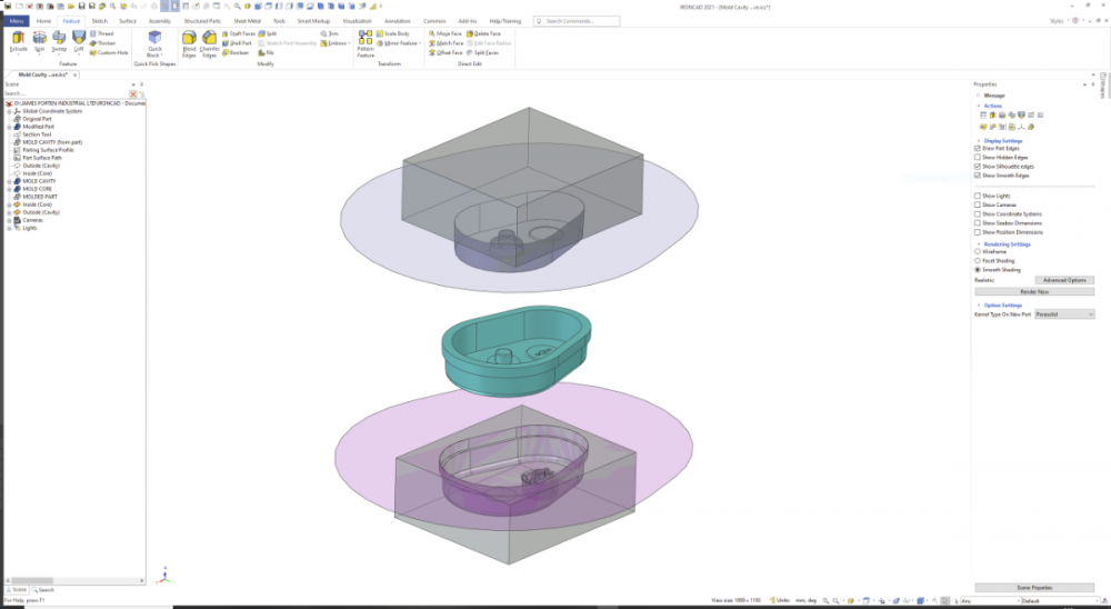
Hi, With the part now suitable for injection molding, attached is a video demonstrating how to create the "Cavity Parting Surface" and the "Core Parting Surface" needed to create the "Cavity" and "Core" halves of the mold. This demonstration was done using "Innovative Part" mode, but personally I would always create plastic molded parts and their associated mold cavities and cores using "Structured Part" mode, so that everything remains associated to each other. I've also attached the scene file used in the demonstration video. I hope this helps give some ideas. Malcolm Mold Cavity and Core - Parting Surfaces.mp4 Mold Cavity and Core - Innovative.ics
 3 points
 -
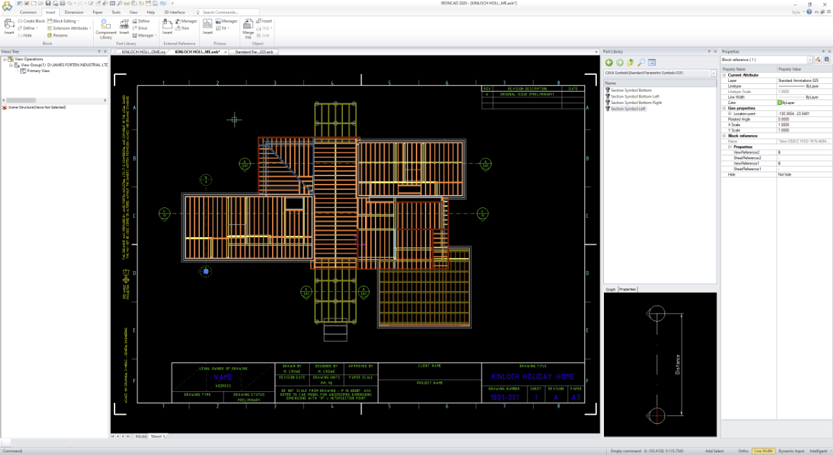
CAXA Symbols are special Blocks of Geometry (and Attributes) that are stored within the "Part Library". They are special in that they can be easily drag and dropped into the drawing, can contain multiple views, and can be driven by parameters (similar to AUTOCAD's Dynamic Blocks). The attached videos demonstrate how CAXA Symbols can be used for creating and inserting Parametric Sectioning Symbols (where the length can be adjusted). 1. Defining and Inserting (the process or steps involved) 2. The use of Expressions (for defining geometry locations) and Part Library Manager (for editing existing symbols). This is a very basic example of a Parametric Symbol, with only one driving dimension. Hopefully the process is simple enough to encourage users to try this capability for themselves. Note that the process is similar for more complex symbols with multiple driving dimensions. Malcolm CAXA - Parametric Symbols - Defining and Inserting.mp4 CAXA - Parametric Symbols - Expressions and Manager.mp4
 3 points
 -
Here is your teardrop shape along with our full MagSHAPES catalog. My gift to Everyone for XMAS! Tom https://magnacad.com/wp-content/uploads/2019/11/MagSHAPES_2020.zip3 points
-
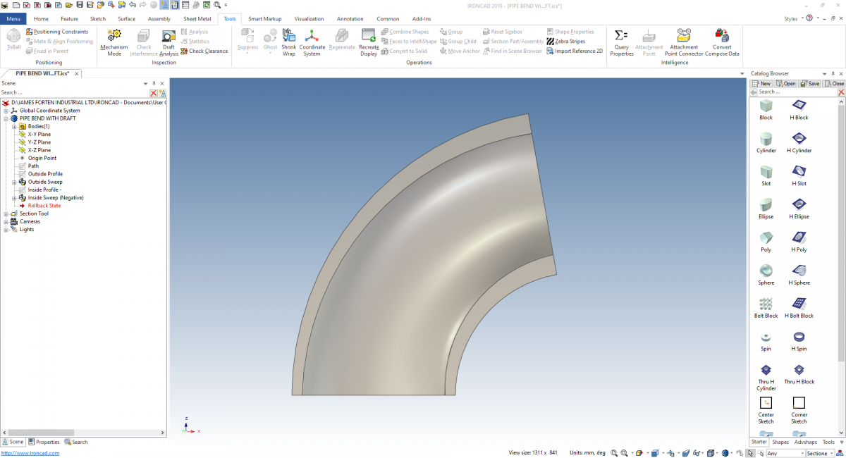
Hi Emil, The way to approach this is using the "Sweep" tool, as it has the option to apply draft through the sweep. Attached is a video, image, and model demonstrating this. I hope that helps. Malcolm PIPE BEND WITH DRAFT.mp4 PIPE BEND WITH DRAFT.ics
 3 points
EmilRindell.thumb.jpg.29678b5c5d1acabccc15c66d12b57b42.jpg)