


Jonas@Solidmakarna
-
Posts
2,287 -
Joined
-
Last visited
Content Type
Profiles
Forums
Blogs
Downloads
Articles
Gallery
Everything posted by Jonas@Solidmakarna
-
Bug? - See through sheet metal problem
Jonas@Solidmakarna replied to HDEAR's topic in General Discussion
You could try to reset the Camera (double click with the mouse middle button, or press [D] or [F8] on your keyboard) or turn off the Perspective projection with [F9]. Does it make any difference? -
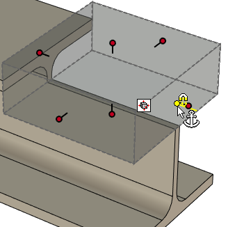
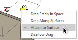
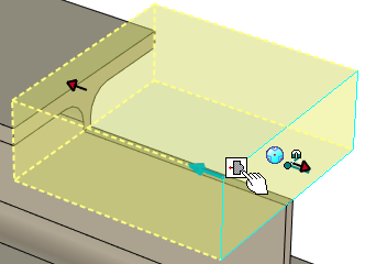
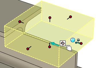
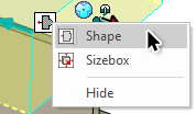
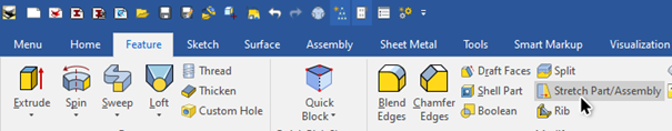
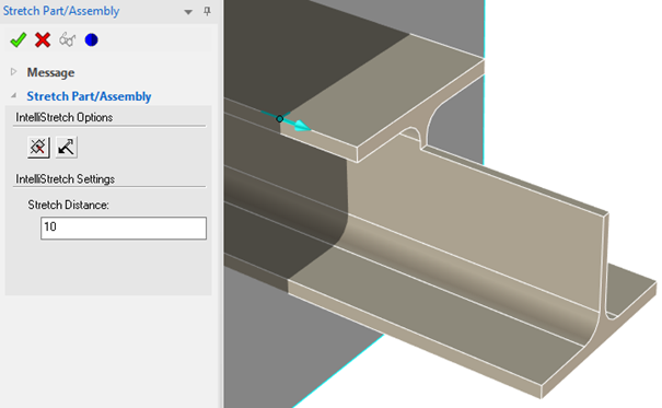
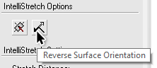
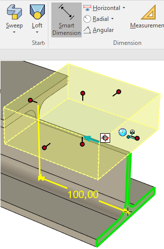
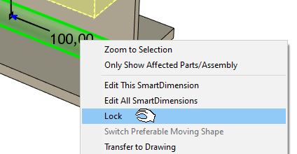
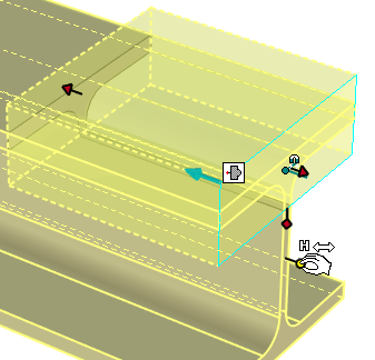
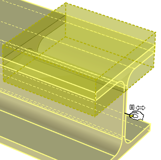
1) Using the Anchor Point as the sole master of position (Standard IRONCAD behavior) The (cut) feature will just "automatically" follow the length of the part when it is made shorter/longer. You need to make sure that the Anchor Point of the (cut) feature is placed at the front face of the part and set to Attach to Surface. Note: This is always being done when you drop objects from the catalog to a (green highlight) face. In general, you seldom think about this at all, but it is an important “fundamental rule” of the system! In case you need to move the Anchor Point, select it (yellow color) and use the TriBall to place it on the face. Then right click and set it to Attach to Surface. When the feature that controls the front face is changed, this will force the Anchor Point of the other shape(s) “attached to it” to follow. 2) Selection is the master of size and position (Standard IRONCAD behavior) As I see it - I am the (sole) master of size and position, not the system. When you are about to change the length of the profile by using a handle, also select the other shape and make sure it is using the Shape handles (not the Sizebox handles). This is easily done by a single tap on the [TAB] button or by the Edit Handle Toggle icon (white): <-> You can also right click on the toggle icon and choose. Selected shapes having the Sizebox handles “active” will change the dimension of the shape (being stretched in the same direction). Selected shapes having the Shape handles "active" will change the position of the shape (move in the same direction). Now, hold down the [Alt] and [Shift] keys and select the shapes (features only) to change and drag a Sizebox handle to edit the length of the steel profile. Since the cut shape is also selected (with Shape handles active) it will also follow. This example became quite long, but this is a lot easier to do than you think. Note: By combining different kind of shortcut keys, you can make an ("unholy") mix of assemblies, parts and features in one go! =) Just turn on the TriBall and move wherever needed. No constraints will hold you back! Note 2: The "shortcut keys" mentioned above; Hold down [Alt] [Shift] for Features (IntelliShapes) only. Hold down [Ctrl] [Shift] for Parts only. Start with the topmost level (assemblies) with [Shift] only or [Ctrl] select assemblies in the Scene Browser tree structure, then add Parts and IntelliShapes as you like, by mixing these shortcut keys accordingly. 3) Using the Stretch Part/Assembly tool Quite similar to AutoCAD and kind of like how point 2 works "in the background" - set at stretch plane and the dimension, done! All that is cut by the plane is stretched while all in front of the plane will move accordingly. Select an edge of the part. The stretch direction (blue arrow in the stretch plane center) might have to be reversed. Fill in the Stretch Distance and then hit apply. 4) Using a Smart Dimension as a constraint (my personal last option for general work in IRONCAD) First, select the (cut) feature and then select a face created by the feature as the first end of the dimension. Then click on the front face of the part as the second (or wherever you want it). This dimension can now also be used as a way to control the position of the affected shape. But it is not a constraint (yet). The TriBall positioning tool and the Anchor Point “rules” still apply. Right click to Lock the dimension as is - it is now also acting as a constraint. The TriBall and the Anchor Point will no longer work to move the shape, until the locked dimension is unlocked or removed. When the feature that controls the front face is changed, this will force the constrained shape(s) to follow. Note: Constraints can be very useful (and a must) in specific "fully defined", always-by-the-book situations, but as the names says they also "constraint" what you can do and how you should think! When you actually want to be free to do whatever change you need - it might not be possible! In IRONCAD, constraints are really not needed in many situations where you, in "old school parametric 3D CAD", always would use them for the same kind of control. With other tools and an open mind you will find nice solutions on your designs!
-
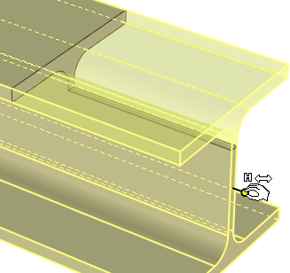
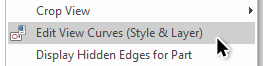
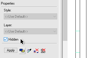
Maybe you can use the Edit View Curves (view needs to be set to Precise Mode), then hide the individual curves? Select the curves and choose the Hidden setting and hit Apply and then OK ("Apply and Exit").
-
Would be really nice to try them out! But seems to be NZ only! https://panheadcustomales.com/ https://panheadcustomales.com/pages/shipping
-
You should also take some minutes and watch the basic training material regarding catalogs and anchor points: https://www.ironcad.academy/tutorial/training-56-catalogs-part-1 https://www.ironcad.academy/tutorial/training-58-anchors-part-1
-
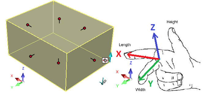
Everything is positioned relative the XYZ space in IRONCAD. This is controlled on each item by the Anchor Point. When dropped from a catalog it has a set direction parallel to the XYZ coordinate system. Long leg (blue) = Z and short leg (red) = X. You can download the Anchor Point guide (PDF) from here: https://www.ironcad.academy/downloads
-
No, I agree with you. But I've noticed in several cases lately that dragging the Part will also make the other parts within that Assembly to follow (as if I dragged the Assembly). I'm not sure if it is intended or a bug
-
There's a Ticket 9227 for adding a switch to control the default setting and Ticket 8738 for creating a new section for all default Mechanism Mode settings under Options, Interaction. Ticket 2670 for control of the default Dragging Behaviour and Ticket 8521 to be able to hide Scene Elements (like constraints, dimensions, patterns, attachment points etc). There's also a Ticket 7092 which includes the Recreate Display function to be used in the background when you leave the Mechanism Mode, since it sometimes happens that you get some graphical artifacts (green faces/edges) when closing the tool.
-
This model works fine! But you must adjust the value on the angle (0° to 90°) and add another 90°, like this: I also added a locked dimension from the top (or bottom)... You don't really need the Collision Detection and you don't need to change to the Assembly/Part filter either (where you must click another time to "drill down" to the sub assembly. Mechanism Mode.ics
-
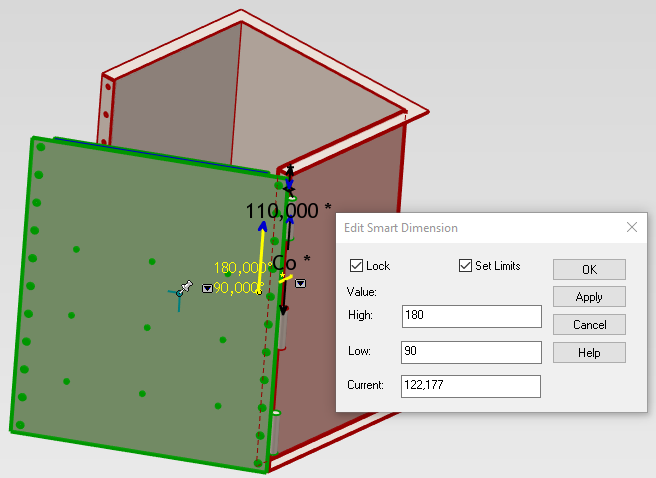
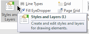
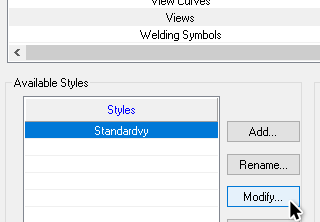
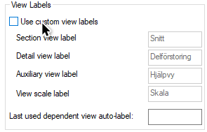
This is due to the new View Label for the Scale text string introduced in v2021. No such label has been available in previous versions, so the text box seems to fill itself with a random string from the code. You can turn off the View Labels for the drawing for now, which will solve this. Go to the Styles and Layers (use the [L] keyboard button) and then select Views at the bottom of the list. Select Modify for the selected Views style and turn off the View Labels (where the View scale label is new in v2021). I think the R&D team is looking at a way to manage legacy drawings better when using a View Label, specially when you have localized (due to native language) drawing templates.
-
For the more advanced short cut key user - left (not sure whether are available for all models) or right handed - I've been recommended this kind of keyboard from some users! I've seen it used in action while working in the 3D scene and I never felt so slow... https://gamepol.com/razer-tartarus-v2-vs-logitech-g13/

-
Instead of using the Move command, just select and move the selected lines directly. This was actually the only option until v10 when the current Move command was introduced. Sketch_MoveCopySelection.mp4 If you drag with the left mouse button there are no questions asked, but when you drag with the right mouse button you'll be presented with Move/Copy options (as usual in IC). The knee point closest to the mouse cursor will be the "origin" of the moved selection (I noticed now afterwards that the circle actually "stole" the origin from the bottom left corner in the video - the mouse cursor was maybe "close enough"). But make sure you don't drag the knee point! It will distort your shape. Tips'n'Tricks: Hold down the [Ctrl] key to create a copy directly (no questions asked) with Left mouse button. This is MS Windows standard and works everywhere with your selection that is moved. Hold down the [Alt] key to lock the Horizontal/Vertical direction.
-
Yes, the multi-thread is for Parasolid *.X_T and ACIS *.SAT, since they are the native formats. All other formats are run through the SPATIAL translator, so when the external developers of the translator has made it multi-threaded we will benefit of that as well.
-
The file import in IRONCAD is multi-threaded, but there are parts of the import process (file conversion) which isn't yet, until the third party application used for the conversion will support it too. Here's what I see (CPU at 92,2%) when I import in version 2020, on my HP Zbook 15 with a 2,71GHz Core i7.

-
training IronCAD Academy Feedback/Suggestions
Jonas@Solidmakarna replied to Josh's topic in General Discussion
I can only agree with Dariusz! I recommend everyone who has not been to the Academy to pay a visit! I've learned much myself och den finns på svenska! -
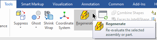
Try selecting the part and then click on Regenerate under the Tools tab.
-
Mechanical - Face to DXF - Saves in Wrong Location
Jonas@Solidmakarna replied to Malcolm Crowe's topic in General Discussion
Hi Malcolm, Check under your Windows Start menu for the IPROSettings tool. There you have all the settings for library folders etc. I think the path for export was affected by an IronCAD update recently, but I think it was fixed with a newer release of IronCAD Mechanical. The Face to DXF settings and export path are controlled under the tab Utils.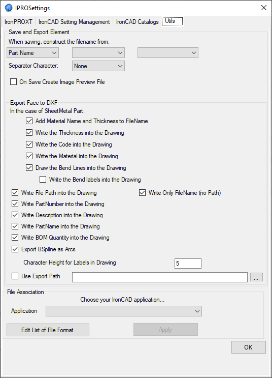
-
I think there is (or has been) a known issue with the direction of locked SmartDimensions that flip in the way you describe, which I'm sure Cary can answer better on. He might have some other workarounds too, maybe similar to what Gustav told us here.
-
Request: Dynamic Naming - Part (User) Name
Jonas@Solidmakarna replied to Malcolm Crowe's topic in General Discussion
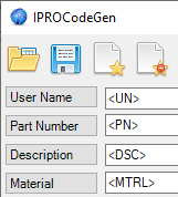
Good question! When I use the tool on "pre-set" parts = parts that already have values like a Part Number etc, I create variables that "recreates" them. <UN> for User Name (don't use the brackets when creating the Variable, only when they are being used) <PN> for Part Number <DSC> or <D> for Description <MTRL> or <M> for Material. Then I set any of those values "to themselves" . There's usually no point of adding them all at once like on the image below, it's just for show. This means that the values are never changed from what it was already using, whenever I use the tool.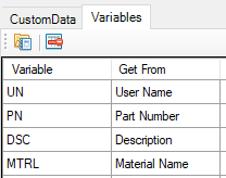
-
Edited Part Numbers Not Displayed in Patterns
Jonas@Solidmakarna replied to Malcolm Crowe's topic in General Discussion
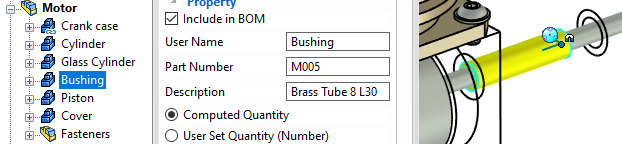
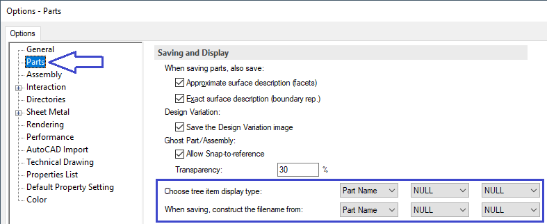
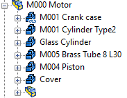
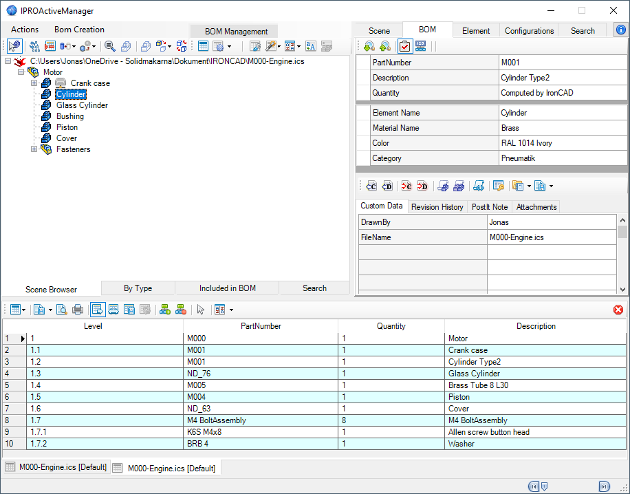
There are really several ways to manage the User Name, Part Number and Description values and don't forget the Material and all sorts of Custom Properties (such as Supplier, Color, Category, Surface Tolerance and others alike that can be shown in the drawing or used for creating configurations). The first three values are always shown at the top of the Property Browser, why it might be useful to place it beside the Scene Browser. The Part Number can be considered as the most important value, since it is the single property that tells the system about an objects identity (there's also a more hidden individual System ID on all objects, but we never need to care about that). Part Number is the main controller of the quantity for the drawing BOM, for example. The Description is for many users used as the same value as the User Name, which in a way is a bit of a waste of "property boxes". Some use it instead to describe the raw material of manufactured objects based on a standard item like a metal plate or a steel/aluminium profile. For example, Plate 130x45, T=5 or HEA100, L=1500 etc. For fasteners it is useful to describe the standard type, while the Part Number, at the same time, uses the individual values of the fastener like type and length. Unless you are using an internal numbering system for standard parts, then the type/length values can of course be set to the Description instead. The User Name is usually just the label or name of the item, such as Fixture Right or Left side Tube or similar simple names like that. It is also the default property being used for the File Name (and export based on selection) setup. Though it can be very useful to make it read combinations of other properties, to make it easier to find in the Scene Browser. There are settings under the IC Options, Parts to replace the visual appearance of the User Name (it doesn't actually replace or create the value) in the Scene Browser. For example to create a combination of Part Number and Description, instead of the User Name. This can also be set when saving. The settings below will change the appearance in the Scene Browser. Now, note that the Glass Cylinder and Cover is obviously missing a Part Number value and that the Fasteners assembly is "blank" since it doesn't have either a Part Number (it doesn't really need one) or a Description (might be useful, but not really needed either, it's "just" a simple container of fasteners that I've made to make the tree shorter). All of these values are managed manually in the Property Browser and personally I think that you end up clicking a lot, but still don't get the full picture. So, I use the IPROActiveManager tool from the IronCAD Mechanical extension to get a better grip of what's done (or really, what still needs to be done) in a more "administrative" purpose. It also has a built in BOM, where you can control (real-time edit) all the properties you expect to see in the drawing are added.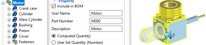

-
Request: Dynamic Naming - Part (User) Name
Jonas@Solidmakarna replied to Malcolm Crowe's topic in General Discussion
Hi Malcolm, This can be easily be done with the Code Generator tool of the IronCAD Mechanical extension. There are many variables that can be read from the model and the scene, to act as text/number properties on parts and assemblies. Very short video on what the tool does: An old video on how to tool works. It has been updated quite much since.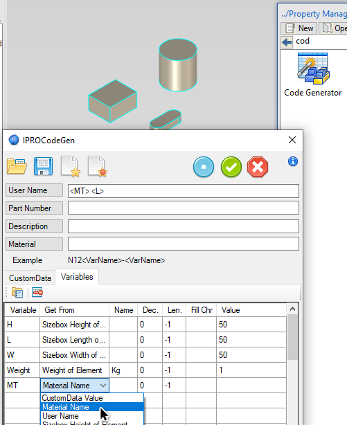
-
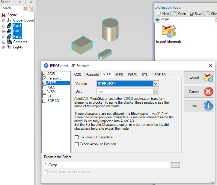
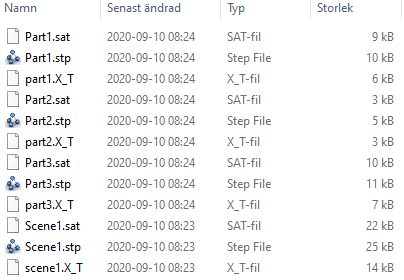
Hi Malcolm, With the IronCAD Mechanichal extension you can use the Export Elements tool for this. - Nothing selected -> the whole content of the scene (the ICS file) is exported to the selected format(s). - Items selected -> they are individually exported to the selected format(s). Here are two exports where the first was run with nothing selected (scene1...) and the second with the three parts selected when the tool was dropped from the catalog:
-
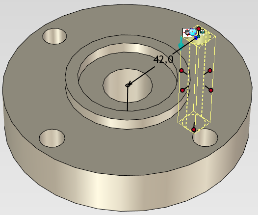
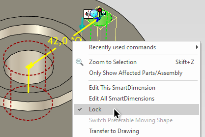
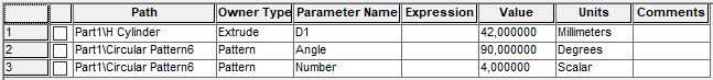
For fully predictable table controlled parts or assemblies, it doesn't have to be a problem do control them by numbers in a parameter table. Maybe even the opposite. But I would never do that myself on general mech parts that are made in a milling machine or general bent sheet metal parts in an assembly. Parameters are too much work and you don't even know if the rules will apply later when you or your customer finds that you must make some late and unexpected changes, whatever reason. Make sure to select the feature you want to "drive" first. The first " click" of the Smart Dimension must be somewhere on that feature (or whatever object that is selected). Btw, if you hold down the [Ctrl] key when left click, the Smart Dim will snap to the Anchor Point of the selected object, which is sometimes useful. You can then control the position of the object without necessarily "being" on the object itself. Holes usually (recommended) have the Anchor Point on the center point of the sketch location. Then, the Smart Dimension must be locked = act as a constraint. If you make the Circular Hole Pattern using the TriBall (not as rotated Linked Copies) or by using the Feature Pattern command, it will also show up in the Parameter Table. Then you can control the Angle between and Number of holes.
-
Better lighting tips
Jonas@Solidmakarna replied to MB-Furniture's topic in Realistic Rendering and Animation
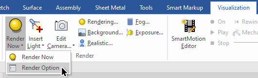
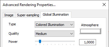
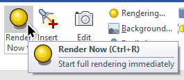
Hello Martijn, I think managing the lights is the answer to all your questions. With that said, it's not always that easy and I like using KeyShot better than tuning in IC. But it is possible with a few tricks.. 1) Turn off the lights and use Global Illumination instead. 2) Use a single color (white) background or an HDR image. 3) Use better materials/colors on the models which you can find in various catalogs. Here's a PDF compendium with more details on those tips and tricks regarding the rendering tools in IC. 08 - Image Rendering.pdf As stated before, it is important to turn off (all) the lights in the scene before rendering. Then use the Global Illumination functions instead. You need to fiddle with the Color (white or light blue or maybe even light grey) and the Power. Don't raise the Power too high, usually only a few "tenths" of the scale. Then Render the image with Render Now (or with [Ctrl] [R])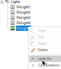
-
Here's a short video on the tool mentioned by Blake.

