


SHORNBRO
-
Posts
79 -
Joined
-
Last visited
Recent Profile Visitors
701 profile views


SHORNBRO's Achievements
")
Cylinder (3/9)
9
Reputation
-
Cary, I might have solved the problem, inadvertently. I had installed the 2024 Service Pack #1 Full Installation (had not previously installed IC 2024 yet). After this issue, I uninstalled and installed the original lease, and then installed the Service Pack #1 patch. It seems to now remember my added custom properties across various instances. - Sam
-
Thanks Cary, I tried running as Administrator and it still doesn't seem able to save the added properties to the list. I'll continue poking around. - Sam
-
Hi all, I'm having some trouble with my Default Custom Properties in the latest patch of IC 2024. For our BoMs we have a few custom properties that pull automatically into them and are set at the part level. It's been a while since I've tinkered with setting these up, but every time I close the instance of IronCAD, it wipes my added custom properties from the Default Custom Properties list in the Options menu. I'm likely missing something completely obvious, but was hoping to get some additional insight on here. Thanks! - Sam
-
Thanks Kevin. That's what I hoped for and figured it would do. Just wanted to check before taking the plunge. Best regards, Sam
-
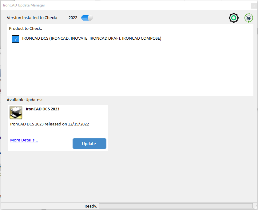
Hi all, On a whim this morning I checked my IronCAD Update Manager and noticed that it shows IronCAD DCS 2023 as an "Available Update" (see snip below). In our office, we haven't yet made the jump to IC 2023 - always paranoid about switching over while we have a bunch of active jobs running through the end of the year, just in case catastrophe strikes. My question is this: would "updating" via this option in the Update Manager actually update our install of 2022 to become 2023? Or will this "update" simply install the standalone IC 2023 application? Best regards, Sam
-
Hey there Kim, 1. I'm not sure I totally understand the question or intent here. Are you wanting to show the "B" Sheet's BoM on all of the other sheets in the ICD document? The way we work with ICD is a bit different from other users, I think, however we tend to use one ICD per assembly/subassembly/part. Occasionally, a complex assembly will have multiple sheets to capture all the details and views needed. With this in mind, on each sheet, the BoM is tied to a specific view or group of associated views (this is to control/unify item bubbling). Sometimes we have to get creative in order to show multiple (usually cropped) views from different configurations to "share" the same BoM (as visible on the sheet) by building BoMs for these other views off the sheet/paper space. This way item bubbling is consistent, although technically pulling from different BoMs. *If you're interested, I can put together an example as soon as time allows 2. To resize the BoM, you have to Right Click --> Edit (or double-click) to open up the BoM. Then you have to manually adjust the column widths (and heights) to fit your space. Hope this helps a bit. - Sam
-
I may not be totally understanding the question, but I put together a quick video and have attached a quick and dirty scene to show how I might tackle this. My test case is simplified, but hopefully will get the point across. Essentially, I would just project and trim the panel cross-sections to match my sketch edges/limits per panel. 2022-05-12 09-18-31.mp4 As far as accomplishing all of that within one command, I don't know. Typically, when we have to adjust grating profiles we will do something similar to this, although in my work I deal with relatively small areas to cover (narrow walkways and small platforms). Hope this helps come up with an idea that works. - Sam Scene1.ics
-
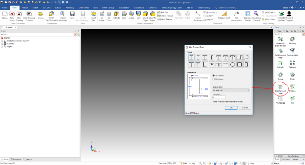
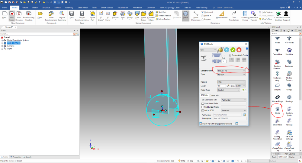
Hi there, If these Steel Sections are in an Item/Group in a Catalog, then it is simply a matter of opening that catalog on the other computer (Save the catalog from the 1st computer, transfer to 2nd computer via USB/Email/Network, then open in IronCAD on 2nd computer). Please find the two snips attached below showing a couple of options depending upon your setup. I personally use the Default IronCAD "Hot Formed Steel" catalog for the majority of structural shapes that I use while modeling. Best regards, - Sam ANSI Steel Shapes in Default IronCAD Catalog - "Tools": More Options Using ICMechanical Catalog - "ICM Mech":
-
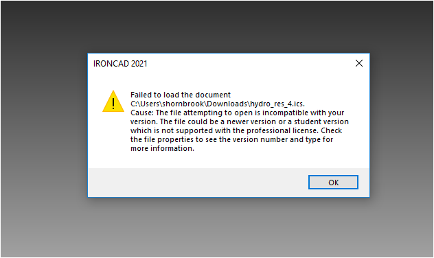
Hi, Unfortunately, I'm not able to open files made in the Student version with my 2021 installation (I keep several past version installed just in case something comes up in the office). I think I have an idea as to what might be your issue, though. Could you send a few snips or video of the model? We work with sheet metal almost exclusively and, occasionally, if you adjust your stock/bend Intellishapes in a way that will break the unfold they will just disappear from the model. It seems to generally happen when the add stock (attached to a bend) is edited, and then the bend handle is pulled (see snip and video below). The way around this for us has just been practice in building our sheet metal parts and developing a workflow that helps us avoid these kinds of issues. Typically with bends we adjust cross-sections to give appropriate relief and transitions into/out of the bend shapes. Please let me know if this doesn't seem to be the problem you're encountering. Best regards, - Sam 2022-03-01 09-07-35.mp4 2022-03-01 09-07-35.mp4
-
Hi Harley, Over here we have run into similar "problems". When we began externally-linking part/assembly scene files (with the goal of creating a 3D Standard Part library in which all of our standardized equipment shared externally-linked parts and subassemblies) trying to decipher some of the tool tips and dialogs was nerve-wracking. In your case, "Do not process linked files" just means that when you "Save As", it does nothing to the linked files associated with what you are saving, hence everything was still linked (any linked parts contained within the newly-saved assembly scene would point back to their original external link location). One method to achieve what you want is as you described - to use the "Find References" and unlink everything manually. This is, as you know, quite tedious. Another method that we have used is to use the ICMechanical tool called "External Link Manager", this will allow you to completely unlink everything in a scene (or individual parts). The only caveat with this is that unlinking everything also breaks internal links between parts, which can be annoying when you have a lot of linked parts/subassemblies that then have to be deleted and replaced (to maintain internal links, but have no external links). Using this tool seems to be the safest method we have found to quickly, and relatively safely, unlink many parts/assemblies. Hopefully this helps - I know how nerve-wracking it is working with externally-linked files and not being 100% confident it will work the way you intend. Best regards, - Sam
-
Inventor 'View cube' on scene positioning plane - equivalent in IC?
SHORNBRO replied to HDEAR's topic in General Discussion
Hi Harley, I had a similar experience when starting in IronCAD - the orientation cube in Inventor is really handy. As you noted, we do have the "Front/Back/TFR/etc" selections along the bottom row (I have most set to keyboard hotkeys), and these are useful, but not quite the same as the cube. In my first day of using IronCAD, I built my own orientation cube that I use from time-to-time and keep at the top of my catalog. Although not a perfect solution, it works in a pinch to help me mentally/visually work out certain view angles. Hope this helps. (Obviously anybody could make this in about 2 minutes, but figured I'd share it anyways). Best regards, - Sam 2022-02-17 09-16-19.mp4 ORIENTATION TOOL.ics -
Hi Geoff, Not a problem. Hopefully my previous examples (I went a bit overboard) can help someone else later on. The IronCAD Academy tutorials are helpful, but sometimes there are little tricks and techniques that may get overlooked. Much of the time while working on a scene, my fingers just go into auto-pilot and I have to really slow down and consciously be aware of what I am doing in order to teach someone new how I go about making models at work. Fortunately, everyone is pretty helpful here on the forums and eager to tackle problems big and small. Best regards, - Sam
-
Hi, For clarification, is there a specific shape/profile you are trying to build? Also, if you can, post a quick video of what you are attempting or the scene file (.ics) so we can try to troubleshoot a bit more. I've attached a quick video that shows me placing a base block, then adding another Intellishape block to that part. You can drill down (keep Left-Clicking) to cycle through Assembly-->Part-->Intellishape-->Faces-->Assembly-->Part-->etc. By default, I believe, Assemblies are yellow-outlined; Parts are cyan-outlined; Intellishape "blocks" are pale yellow-highlighted; and Faces/Surfaces are green-highlighted. Typically if I am building using blocks (most of my work is done with sheetmetal parts), I will place a base block and build off of that by dropping additional Intellishape solid and hole blocks (cube/cylinder/slot/etc.) and then edit their cross-section profiles once I have roughed-out the general feature structure. At the Intellishape level, I use the Shift key dragging on the handles to line edges up with certain features to edit the Intellishape. Generally, unless it is a specific case I don't drag the Face (green-highlight) to build Intellishape features. That being said, you should be able to drag the Face and have it Shift key snap to another Vertex/Edge/Face (see 2nd video clip). To my knowledge, the Shift key snaps should work by default. When you say that "it just shows the handles on the basic block instead of the green face or edge," are you actually grabbing the Extrude that is created if you already pulled a Face (green-highlight) in/out? It should show in your Scene Browser (assembly tree pane) what features make up your part. If you have only dropped in Intellishape blocks, it will show those. If you have drilled-down and dragged Faces (green-highlight), then that should have added an Extrude feature into the part tree. If clicking on the part itself to try to select the Face (to use its handles), then the Extrude (made from the face) might be getting in the way (see 3rd clip). Hope this helps and doesn't muddy the waters too much. Best regards, - Sam Clip 1: Clip 1.mp4 Clip 2: Clip 2.mp4 Clip 3: Clip 3.mp4
-
Hi there, If you want to keep pulling them in as a catalog item and have them internally-linked within whatever scene instance you are working from, the only way I know how to do this would be to externally-link the part, add that to the catalog, and then whenever you drop the part into a scene it (and any others you wish you drop in) will be externally-linked to that outside scene file (and in-turn, all "copies" within the scene you are working in will also be effectively internally-linked). *Apologies for the long-winded, run-on sentence there. For instance, my company builds a variety of different equipment, some of which are very similar and can reuse common parts. We have gotten into the habit of externally-linking out every part of each assembly of a machine. We can then insert these common parts into any other equipment we choose. The only caveat with this is that we have to be careful that we (or someone who isn't aware/knowledgeable of our processes) can't accidentally alter a common part which will affect a large variety of different equipment. My preferred alternative (and sometimes safer method) would be to keep the part in the catalog as you currently have it (not externally-linked), drop the part in the scene as you need it, then "Copy As Link" the part as many times as you will need it (for alternate instances or different assemblies). From here you can then "drag" those copy-linked (internally-linked) parts within the different assemblies using the scene browser for organization. They should retain their internal links, despite being pulled into many different assemblies. I will try to put together a quick video in a little bit to demonstrate if that will make it a bit more clear to conceptualize. Best regards, Sam
- 1 reply
-
- 1
-

-
Actually, there is a Checkbox, though it is not in "Part Properties." Intellishapes are treated as sketch extrudes, and as such you can toggle between "Add Material" and "Remove Material" within the "Edit Feature" dialog of the Intellishape properties. See the attached video - hope this answers your question also. With this in mind, I also use the method Spencer suggested as well - creating cataloged Hole Shapes is as easy as creating cataloged Solid Shapes. - Sam 2022-01-04 09-18-52.mp4


