
Jonas@Solidmakarna
-
Posts
2,277 -
Joined
-
Last visited
Content Type
Profiles
Forums
Blogs
Downloads
Articles
Gallery
Everything posted by Jonas@Solidmakarna
-
The 3D Scene ICS file is a database "container" of various data and sometimes it can happen that parts of the file becomes corrupt. When this happens it usually never affects the solid 3D geometry, but other parts of the file data. In your case it seems to be the graphical facet display data that was corrupt. If the file can be opened, you can drag the content into a catalog and then drop the content back out in a new 3D Scene file. If you cannot open the file, you can try to create a new 3D Scene and then Insert the problem ICS file into it. All you get is the solid data (the assembly tree structure will be intact). Remember to remove the external link (unless you didn't remove the link at Insert) from the top assembly. You don't want to have a link back to the problem file itself. You can then save the file in the same folder and add a little something to the file name. Then rename the files after you have closed IRONCAD. All other files with links will just look at the file name, so there's usually nothing more you need to do.
-
Transfer intellishape depth to 2D drawing for DXF export
Jonas@Solidmakarna replied to LSMITH's topic in General Discussion
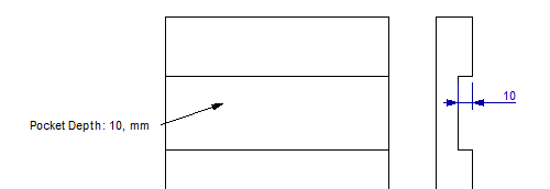
Hi Logan, Is the Panel part or the Pocket feature ever being reused? Do you create new parts and features every time, or do you use a catalog to store them or do you open old files and make the changes (then save as a new file)? If you reuse them (dropped from a catalog or save as new file) you can standardize this in several ways. There are probably more than these two. 1) Use the Smart Dimensions which are being transferred to the Drawing, like the ones that you have on the images. But as you say, I don't think you can (currently) show the dimension on the Front view. 2) Create parameters which are read as Custom Properties that are transferred to the Drawing. Then show the Custom Property info in a text block or in the BOM in the Drawing. In one way, even if it adds some clicks, this is pretty fast to to for any new feature if it saves time in the end. If this sounds interesting I can record a video later. You can control the direction of each part using the Front View Direction option on each one. Is the Drawing showing all parts in one View or do you create a View per Part in the same Sheet or do you create one View (or more) per Part in one Drawing file? Using the Bulk Drawing Creation tool could maybe save you some time here, and I think it can do any of those three choices above.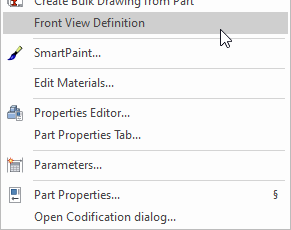
-
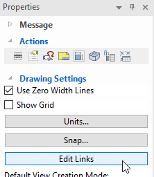
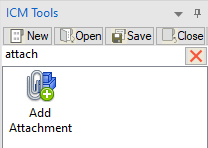
Hi Jeff, There is no association between the ICS and the ICD in terms of "where used" (from the ICD -> telling "I exist, you are being used here" back to the ICS). The ICS file can also be "used" in more than one ICD, but it simply "doesn't know" if it is or not. This information is not being (cannot be?) stored in the ICS file. The ICD has a list called Drawing Links (click on the Edit Links button in the Drawing Property Browser) of which ICS files it needs. I know of two ways to get this information; 1) Manually add the ICD as an "attachment" to the 3D model by using the IC Mech Add Attachment tool. It is then possible to create and export (spread sheet) lists using the IPROActiveManager tool of all this information. You can of course attach a PDF file or a web site url if you want to instead! https://ironcad.it/learnICM/en/tools-catalog/0310_add_attachment/ 2) Use a PDM/PLM system like the SQL based DesignDataManager (DDM). It has all of the "Where Used" and "Contains of" functions you need and much more. Btw, these two functions are nicely implemented in the files' tree structure in the DDM window. Expand an IRONCAD file and you will see all the files needed to open it ("downstreams" = assemblies or parts), but you will also see all the files where it is being used ("up streams" = drawings or assemblies). https://www.designdatamanager.com/solutions/ironcad-pdm/
-
Hi Tambolina! If you can spend some time with the basic training videos on the IronCAD Academy (from top to bottom or any of the videos that suits your thoughts), you will be an IRONCAD champ before you know it! This is the intro and the rest of the videos are listed on the left side, just pick and choose! https://ironcad.academy/tutorial/introduction-to-the-basic-training-course
-
Here is a page with a bunch of useful shortcut keys explained (auto-translated into English, but quite ok). https://en.solidmakarna.se/supportblogg/kortkommandon-i-ironcad
-
Cannot return to state after part becomes transparent
Jonas@Solidmakarna replied to tgjang's topic in General Discussion
Have you tried to cancel the new transparency setting that can be applied to the parts (it's not a color setting)?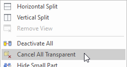
-
Creating a smart dimension on hole feature.
Jonas@Solidmakarna replied to tgjang's topic in General Discussion
There are at least three options! Kevins suggestion is usually the best. Remember that with the [Shift] key, you will always "Snap to Center" in many commands. But you can also; Rotate the camera to see the center of the hole placed in front of the "hole depth" (mantel surface). Typical case on thin models, like Sheet Metal parts. Hold down the [Ctrl] key when the mouse cursor is placed "within the Sizebox, touching the Shape" to place a Smart Dimension from the Anchor Point. A "cyan blue little dot" will appear "behind" the Anchor Point (hint hint, ER please! ). Since a Cylinder Shape dropped from a catalog usually have the Anchor Point placed in its center, it's a useful option. I most often use this when creating parametric models with some locked Smart Dimensions acting as constraints. I usually prefer controlling the Anchor Point (which always controls the geometry) rather than a green face/edge/vertex of the Shape.
-
Adding 'empty assembly containers' to scene tree.
Jonas@Solidmakarna replied to HDEAR's topic in General Discussion
I agree that we would love to see videos about many of the new functions in the What's New documentation. Kevin has added some videos here at the Community too. The new Assembly structure function is "simply" that you can click on the Assembly button and create an "empty" Assembly.
-
According to ISO 5455, there are a certain number of View Scales available. But it can be useful to have more scales available in the drop down menu, which is managed in the MS Registry. Here are some MS Registry (*.reg) files which adds more View Scales (32 in total, like in the picture above) to the ICD, depending on version: IRONCAD v2022 IRONCAD v2023 IRONCAD v2024 Download and run the MS Registry file. Answer Yes, OK, I'll do, All right just stop asking and so on ! Be aware that manually editing the MS Registry can lead to issues. It's good to always open/edit a *.reg file in a text editor to get a hint of what it will do, before you run it.
-
displayed filename as a :1 - what does this mean?
Jonas@Solidmakarna replied to RLUXTON's topic in General Discussion
It's because the Scene Browser has been set to be undocked by default or when a new scene is opened, which is also shown in the image, even though I don't know why it should add this :1 to the file name just because of this. To solve this, double click at the top of the Scene Browser, to dock it back into the program window. Then close and open the file again. -
If you can ignore the effect on other possible drawings etc, the absolute fastest way must be this! 1) Select the object(s) 2) Drop the ICM Set Include in BOM Status (left mouse button toggles all ON, right mouse button toggles all OFF) http://ironcad.it/learnICM/en/utils-catalog/010_set_include_in_bom_status/
-
Single line font for laser profiling of part numbers
Jonas@Solidmakarna replied to dbarber's topic in General Discussion
Here are some that we mention on our support blog (in English) - https://en.solidmakarna.se/supportblogg/20-gratis-typsnitt-for-laserskarning Though I'm not sure about if any of them is a true "single line". -
I see, that was far more complex! Well, then that catalog won't help of course. You'll probably need to make a Sweep shape from 3D Curves or maybe it's possible to build "good enough" even with quite simple drag-and-drop shapes. Perhaps also a Structured Part where the curves are associated with some of the edges from a "base shape". At the moment I don't have time to look at it, but I'll see if I can try quite soon.
-
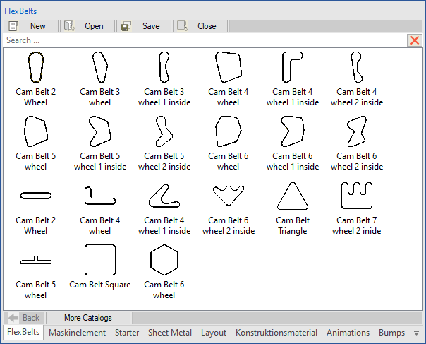
https://community.ironcad.com/index.php?/topic/11939-flexshapes-belts/ Here's the old post. Not that old though
-
Maybe this catalog can help you out? FlexBelts.icc It's a catalog (saved in v2023 PU1) with various "belts" that I made many years ago. There might even be a topic/post with more information about them here somewhere that I can no longer find.
-
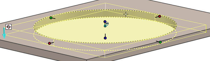
Thanks Kevin. Another thing I didn't know about this is the fact that you can also select objects that are behind the transparent object! So in the video, you should be able to select the various PCB models that you see inside.
- 1 reply
-
- 1
-

-
We placed an ER for that a while ago, Ticket #10643 - ICC, being able to store/drop only the Material value to/from a catalog. It would be a great function to change material without changing color.
-
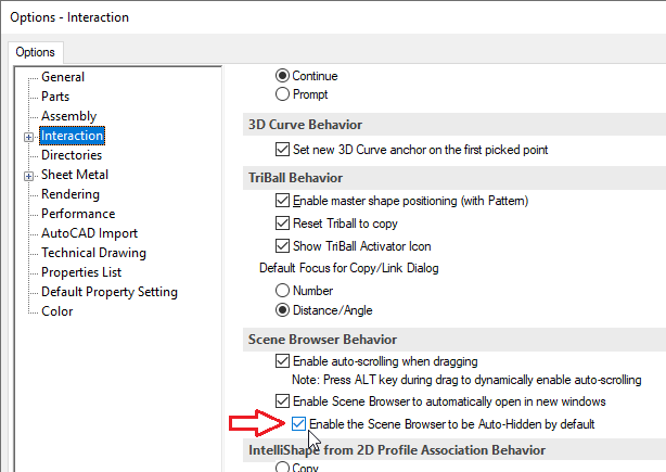
It was probably because of this setting, why resetting the registry also solved this problem. Back in the days (around v5.0) the Scene Browser wasn't shown by default and some didn't even know there was a tree structure for the models you made!
-
Question. When saving, construct the filename.
Jonas@Solidmakarna replied to tgjang's topic in General Discussion
Cary, you can have a look at Color separator for Tree Items Ticket #3552, which includes three other ER's for the tree item display. Add Tree Item Display separator - Incident # 103454. (has no ticket ID #) - what is being discussed in this post. Wants tree display option to show also as part name tooltip - Incident # 104027. (Ticket #1348) Items inside Patterns doesn't make use of Tree Item Display Type - Incident ID#: 108363. (Ticket #3483) I also think these tickets are related and worth looking at; Choose tree item display type - affect the search result in the search tab - Incident # 110494. (Ticket #4758) Filter by color in Scene Browser - Incident # 113335. (Ticket #7130 - similar to #3552) -
Placing a feature at the origin of the coordinate system..
Jonas@Solidmakarna replied to tgjang's topic in Tips and Tricks
Since the "first" part in the video is named Part22 (not Part1), maybe the scene template has some kind of issue with the "first part" dropped from a catalog? Like if it was already done once. Is it the same if you create a new scene and use another template? -
IronCad Academy - 3D curve training - will this be updated?
Jonas@Solidmakarna replied to HDEAR's topic in General Discussion
Hi Harley, You can also have a look at the basic training video 16 | Sweep from around 8:20 and forward. Several videos were updated with v2022 a while ago. https://ironcad.academy/tutorial/training-16 -
Placing a feature at the origin of the coordinate system..
Jonas@Solidmakarna replied to tgjang's topic in Tips and Tricks
In a new empty scene, the first shape dropped from a catalog will always have its Anchor Point placed in the world origin 0,0,0. No need to hold down any shortcut key. Note: The visible geometry and its Anchor Point doesn't have to be at the same location or even close to each other! If you hold down the [Ctrl] key when you drop a Shape (feature) out from the catalog into the scene background, the Anchor Point of both the new Part and the Shape that you dropped will always be placed in the world origin 0,0,0 (as tgjang first wrote). Note: The visible geometry and its Anchor Point doesn't have to be at the same location or even close to each other! If you hold down the [Ctrl] key when you drop a Part or Assembly out from the catalog into the scene background, the Anchor Point will always be positioned in the world coordinate where it was located when it was dropped/stored into the catalog. Note: The visible Part/Assembly geometry and its Anchor Point doesn't have to be at the same location or even close to each other! If you first select a Part or Assembly in the 3D scene and then hold down the [Ctrl] key when you drop a Part or Assembly out from the catalog on the selected Part/Assembly, the selected Part/Assembly will be replaced. For anyone interested, you can learn more about how to use the catalogs and how the Anchor Point is working, with the training material (videos 56 to 61) on the IronCAD Academy site: https://ironcad.academy/tutorial/training-56-catalogs-part-1 -
As far as I know, it is only possible with the IronCAD Mechanical add-on using the Edit TitleBlock tool. Here is a video where this is shown (about 1:45) http://ironcad.it/learnICM/en/ribbon-bar/ribbonbar_2d/020_edit_title_block/ Important: From ~v2022 it is no longer possible to use the "automatic reading" $PRP... text block functions combined with the ICM Edit TitleBlock tool. The $PRP... function in the text block will be overwritten with the plain text controlled by the Edit TitleBlock tool. Though the values can be automatically updated using the ICM Edit TitleBlock tool as well, which is controlled from the IPROSettings tool (from the Windows Start menu).

-
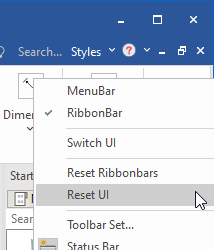
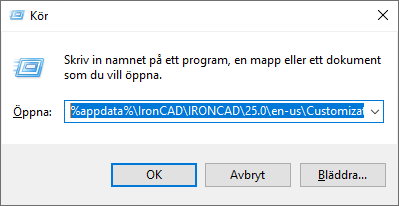
With version 2023 there's a new option to do this more easily. Right click in the top right "empty" area of the UI and choose Reset UI. This will remove those XML files automatically when you close IRONCAD. The XML files are restored when you run and then close IRONCAD again the next time (saving the state of the UI when the last open file is closed). Here is another way to find the path to the XML files, using a "general directory shortcut" that works for anyone exactly as it is (no need of the exact path). Just copy and paste into the address bar of the File Explorer or use the Run command: %appdata%\IronCAD\IRONCAD\25.0\en-us\Customization Other useful directory shortcuts; %localappdata%\IronCAD\IRONCAD\ - where the Cosmetic Thread data table and Sheet Metal Stock and Tool table files are stored but also the XML files that stores the shortcut keys (which you can actually manually manage (restore with a new version), if you know how to read and manage XML files, but please handle these files with care). %public%\Documents\ - where the IC Mech add-on stores tables and other data for the standard components. This could also be a useful place to store IRONCAD-files, if you are more than one user sharing the same computer. It can also be a "general place" to store files like IRONCAD catalogs (*.icc), backup copies of drawing templates (*.icd or *.exb), license documentation (*.pdf) and other useful stuff that doesn't have to be unique to a certain version. Unless you simply want to use your default %userprofile%\Documents\ folder
-
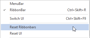
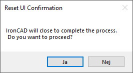
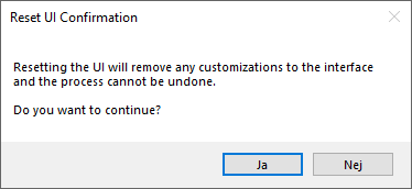
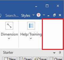
9. Reset UI and Reset Ribbonbars - two options under the right click menu of the user interface. Right click in an "empty area" under the ribbon bar (usually to the far right side). Reset UI - will close IRONCAD and remove all the UI XML files (under %appdata%\ironcad\...). The original UI setup from the default installation will be used instead and the XML files will be created in the %appdata%\ironcad\... folder again when IRONCAD is closed the next time. Reset Ribbonbars - will try to reset the UI (XML-files) while IRONCAD is still open - (probably) similar to the previous Reset UI option that was available before v2023.