
Jonas@Solidmakarna
-
Posts
2,287 -
Joined
-
Last visited
Content Type
Profiles
Forums
Blogs
Downloads
Articles
Gallery
Everything posted by Jonas@Solidmakarna
-
Cary, please check out Ticket #2268 - Add Sweep and Loft shapes to be allowed to be dropped as Assembly Features
-
It seems to differ depending on which image I'm using. Have a look at the attached ICS made in v2022. I cannot repeat this in another scene with another image. Floor.ics
-
Maybe you can try using the Quick Block shapes under the Feature tab? It's quite simple, but you still need the exact points to get it right. I made a little video which might help. QuickBlock.mp4
-
For me, the TriBall moves in the "opposite" direction when I try to re-position it (after hit [spacebar]), so it doesn't work as it should when working with a Decal (set to Slide Projector).
-
Can't open x_ref from assambly
Jonas@Solidmakarna replied to Tomas-Nor's topic in General Discussion
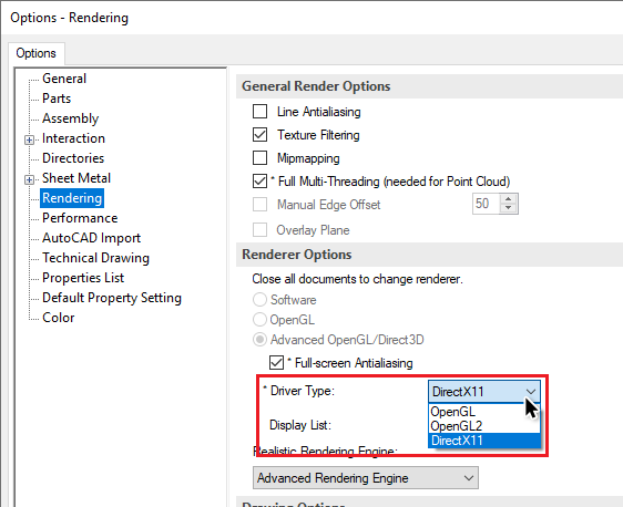
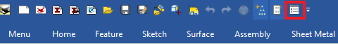
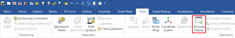
To me, this sounds like a graphics issue with the ICS file or a perhaps even a graphics card (driver) issue, in case you see it on multiple files? Sending it to support will help for sure, but if others have similar issues it might be good to run through some of these things: You can try to run the Recreate Display function under the Tools ribbon tab, to reset the graphical cache data of the ICS file. You should try switching between the rendering engines under the Options, Rendering settings: Also, check the driver version for you graphics card and see if you can update it. You could also try to copy all data (select all models in the tree and do a [Ctrl] [C]) and paste them ([Ctrl] [V]) into a brand new "fresh" ICS file and then just save it over the original (keeping the same file name, but remember to close that file first!). One can also use a Catalog to "jump" over - drop the assembly there and drop it into another file. Maybe the original ICS file is corrupt in some way, making it hard to restore the graphical data. In a way, the ICS file can be compared with a ZIP file and can contain all kind of sorts of data (not that you would want to use it as a ZIP file...). Spencer, I think what you are using is the Visual Load function, which will load the HOOPS graphics data of the ICS file pretty quickly (enabling the camera tools) while the geometrical data for each model takes longer time to read in (models cannot be selected etc until then). I don't know if it really gives the feeling that the file loads quicker? But it's an option and some like it, some don't. You find it under the Options, Performance: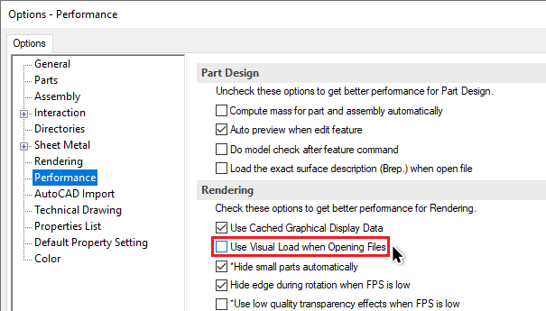
-
Here are some Swedish high quality parts from Alfa Laval, loads of clamps, pipes, fittings, butterfly valves etc! https://ironcad.partcommunity.com/3d-cad-models/alfa-laval?info=alfalaval&cwid=0540 When using the CADENAS Part Library you can choose to download up to 10 file formats at once (in one ZIP file) which I really like! As standard, I have set ACIS 7.0, (which also works great for import into AutoCAD 3D -> exported from IC!) Parasolid V15 Text (not Binary!), STEP AP214 (which usually includes color) and a few other images, PDF etc. Btw, I searched for "tri clamp" parts and found that the "old" standard ISO 2852 has been withdrawn by the ISO committee a few years ago. The active standard now seems to be ISO 2037, which is used by Alfa Laval and others.
-
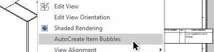
I agree with Sam that you should avoid placing "visual references" (item bubbles, in this case) to hidden objects. But if you show the hidden edges, that might be fine. Though, you should be able to find one of the two dashed vertical hidden edges with the Item Bubble tool? The hole itself isn't visible other than those "edges". Anyway, there's another fast and very simple solution to your question! As soon as you've created a BOM, you can right click on a view and choose to AutoCreate Item Bubbles. In general, it might be too many item bubbles, or placed on the wrong place etc. But it should solve this specific case. Another good option (as Sam also mentioned) is to use a Text with Leader where you can show properties from the selected part. Below is a catalog that you can open (from the Catalog Browser, or just drop into IC when an ICD is opened) in the IronCAD ("White Sheet") Drawing with pre-made text boxes that reads properties from the part you drop on (green snap color). I made this for another user who wanted to read the length (Height/Extrude distance) from pipes, instead of placing dimensions to/from points which was often hidden by other stuff at the ends. TextProp.icc There are also text boxes which reads User Name, Part Number, Description, Weight (based on the weight unit of the drawing), Material and has different directions of the Leader Line and Arrow.
-
I thinks it's the same for all 4 letter file types, like STEP files! STP files are fine and so are X_T, SAT, ICS, ICD and so on... Try changing to 3 letters -> IGES to IGS and STEP to STP. I think it should work.
-
I can also confirm that it doesn't work when using the Apply button. I usually never use the Apply button unless I switch between the tabs in the Property window.
-
As far as I know I don't think you can get the information sent to MS Excel in a way that the values from IC are updated in MS Excel in "real time". But through export of BOM information from the scene or the drawing. It's the same the other way, you must run some kind of function to read the information and the files usually must be saved (I think) before the information is being updated in the other program.
-
Or create another parameter which uses an L/1000 expression and use that parameter to control your shape instead.
-
The default metric Parameter table units are in meters, not millimeters. So divide the expression with 1000 and the value 1 in MS Excel will become 1 mm in IRONCAD.

-
No, the file I tried on wasn't saved.
-
Works fine for me with Swedish Win 10 in both v2021 PU1 HF1 and v2022 Customer Beta #3 (build 17828).
-
Hi Carlo, Here you can download the customized Starter catalog that we use here in Sweden, where we have turned off the "active handle" setting for almost all shapes. https://www.dropbox.com/s/8o7fv81n4bcmi2i/Starter.icc?dl=1 It also contains a lot more other stuff, but you can of course remove all the junk that you don't want or need Though I really like this active handle setting itself - as an option when it feels useful. For example, when I create a shape on a part where it makes sense that "this particular handle" is the active handle (read "the diameter handle of a hole"), because it saves me some time as I most likely (90+% of the time) want to change the dimension in that specific direction. There are a couple of other really useful news coming in v2022 in the same "area", where you can control more settings on individual shapes, like minimum and maximum dimensions and incremental snap distances -> per Sizebox handle! Very powerful!!!
-
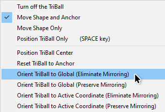
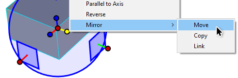
Btw, to remove the "mirror function" of an object in the 3D Scene, select it and activate the TriBall. Right click in the Background and select Orient TriBall to Global (Eliminate Mirroring). In case the plate/model/object isn't "symmetrical with itself", you might have to reposition some of the features withing the parts. Usually this isn't a big task - use the TriBall!
-
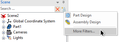
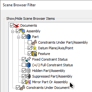
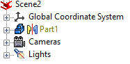
Maybe the part is mirrored (about it's own axis = with the TriBall)? For me, and in practice / IRL, something that has been mirrored is in relation to something that isn't mirrored. But in CAD you can mirror about itself without the need for a "none-mirrored" pair. Click on the Filter icon in the top right corner of the Scene Browser: Select to show the Mirror Part or Assembly filter. An object that is being mirrored "about itself" with the TriBall... ...will now be shown with another text color and an extra "mirror icon" in the tree structure. Remember that this is a function of the position/orientation in the XYZ space and not a relation to another object. In v2022 there will be a new setting for the Part Number and Description to be set differently per object, when it is being mirrored, even if it is linked (in geometry) with other objects.
-
Default method for creating 2d sketch
Jonas@Solidmakarna replied to GNÄSLUND's topic in General Discussion
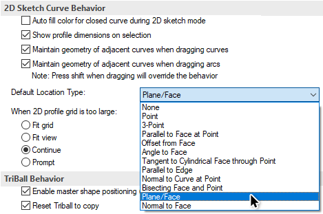
Hi Gustav, If you change the Default Location Type setting for the 2D Sketch under Options, Interaction to Plane/Face, this also seems to fix the automatic "Use Part Origin Point" setting.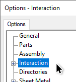
- 1 reply
-
- 1
-

-
As far as I know it isn't possible yet, but it would be very much appreciated if it was added. I have an Incident No #101994 which should be connected to an ER to allow us to control the default setup of the BOM (Item Bubble) Text Frame in the template.
-
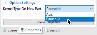
It might be useful to set the default kernel before you import a "neutral" STP/STEP file, depending on which system that exported/created the file. The result from the import might differ depending on the default kernel. With "result" I mean if you end up with more or less surface parts or possible topological issues which can be quite common with STEP files. The fastest way to switch is by clicking on the Properties tab at the bottom left corner and click once in the background ("nothing" selected) and use the drop down menu at the bottom. All new parts created in your scenes will now use this, as this is a global setting and not only for the active scene/file. If you work against//together with a "none Parasolid" kernel based 3D CAD system, then sometimes ACIS might be a better "base kernel" for your models before you export to STEP (or keep the native ACIS *.sat file format to avoid too many conversions between systems).
-
Hi Harley, The only way to control the order is by docking them one by one in the order you want them to be shown. I didn't even know this could be done until I saw your post! Cool! So having each catalog window floating and docking them one by one seems to be working fine. I think the reason Kevin asked about the version was that these"vertical tabs" were the only way to manage the catalogs up until v10/2007 and the "new UI". Then we "lost" the vertical tabs for horizontal ones instead.
-
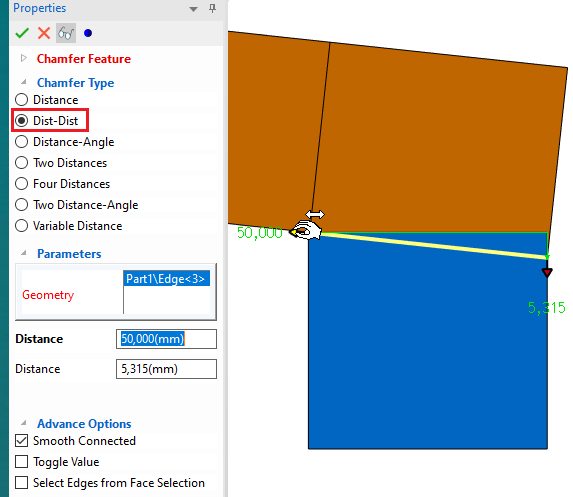
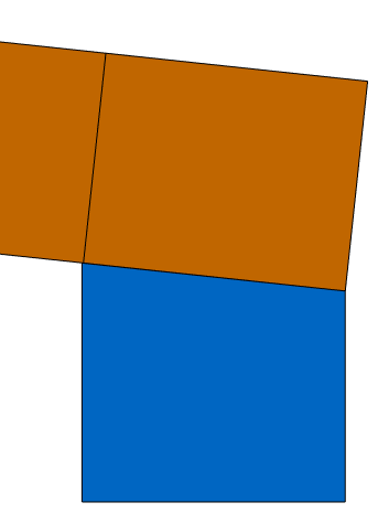
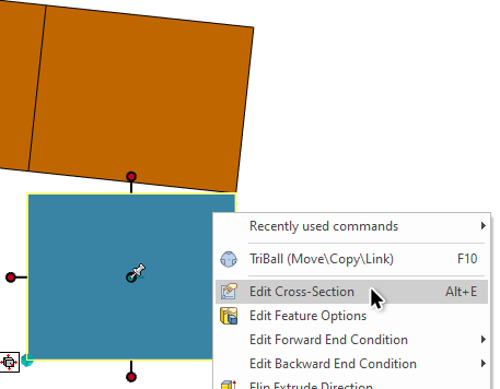
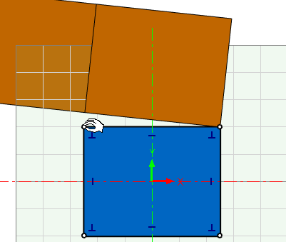
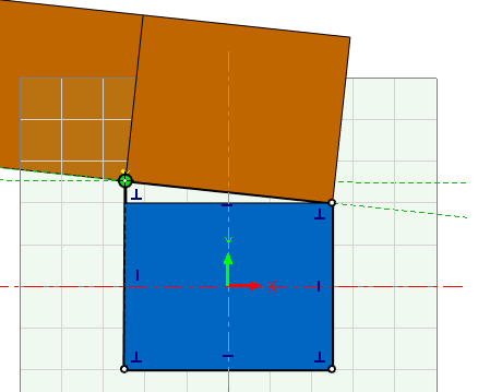
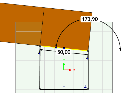
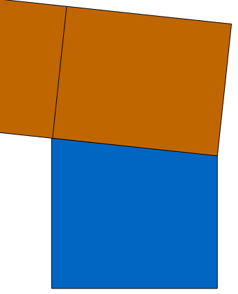
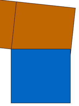
As Mike says, creating a new Sketch based model is a fast way to go! The shapes (pre-made features) in the Starter (and Shapes) catalogs are symmetrical and "simple" in many ways, but they can all be manipulated. If you have dropped a Block shape, you can edit the 2D Sketch (also called Cross-Section) of that shape and make any kind of change to the curves there. But there are other options too! Here are two simple ways with the standard tools; Chamfer feature (Distance/Distance): Make sure the part you add the Chamfer to (the Blue Part in this case below) is larger than (or "crosses over") the other part and matches at least in one corner (top left, in this case below). Chamfer from the top right corner and use the Chamfer feature handles on each side to snap (while holding down the [Shift] key) to the values as needed (or just type them if you know the values): Sketch based edit: How to make the curve fit exactly as how you want it, that depends on your preferences and the shapes. I think dragging a knee point could work in this case. You could also remove the curve and Project a new curve from the edge of the other part. Then trim/extend to make an "unbroken" single contour (of the blue part below). The upper curve will now "match" the other part edge. Finish the Sketch.

-
How to pull out my sketch from an extrude?
Jonas@Solidmakarna replied to Afwe Rew's topic in General Discussion
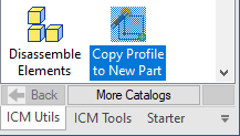
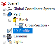
If you have the add-on IronCAD Mechanical installed, there's an easy to use tool there to extract the sketch from any sketch based IntelliShape, like an Extrude, Spin, Sweep or Loft (which has multiple sketches). Expand the part and the feature and select the sketch (Cross-Section). Then drop the tool Copy Profile to New Part, from the ICM Utils catalog into the scene. You will now have another part (2D-Profile) at the end of the tree structure with your sketch!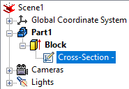
-
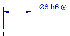
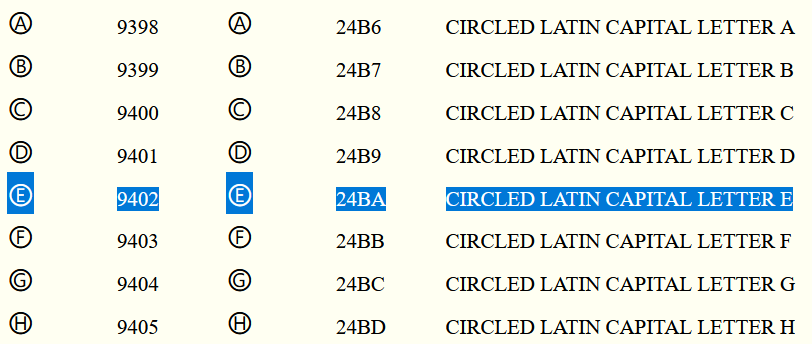
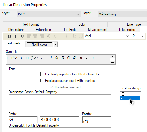
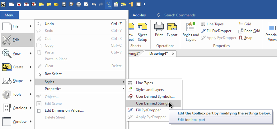
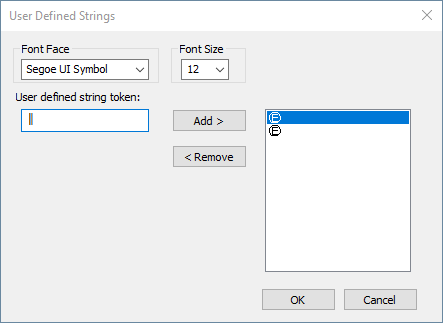
To place an Envelope Requirement on a diameter or linear dimension with an ISO-tolerance, you can use a certain shortcut key sequence to create the symbol as a postfix of the dimension text. Depending on your localization of Windows (language) there might be two optional ways of doing this in IRONCAD. One of these two (or both) ways should be working; Go to the postfix and type 24BA. Select the text string and click [Alt]+[x] and it will convert the "24BA" text to a circled E. Go to the postfix and hold down the [Alt] key while typing [9] [4] [0] [2] "in sequence" on the numerical key pad and a circled E will be created. See this list for a list of other fonts similar http://www.alanwood.net/unicode/enclosed_alphanumerics.html Also remember to place all special symbols in the Custom Strings library, for easy reuse whenever needed! Go to Menu > Edit > Styles > User Defined Strings Type the character shortcut key command (or whatever text string you'd like) and use the Add > button to add it to the list of custom text strings. For me, I had to change to the font named Segoe UI Symbol first and use the the [Alt] key while typing [9] [4] [0] [2] num pad function, because using the Arial font just showed me the wrong symbol.
-
Bug? - See through sheet metal problem
Jonas@Solidmakarna replied to HDEAR's topic in General Discussion
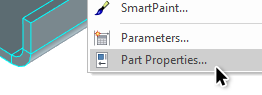
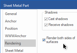
Ok! Try changing the kernel once or back and forth? Looking at your video again I don't think it is a graphical or camera issue. More of a topological or feature issue. You can try using the Render both sides of the surfaces setting under Part Properties, Rendering.