HDEAR
-
Posts
1,019 -
Joined
-
Last visited
Content Type
Profiles
Forums
Blogs
Downloads
Articles
Gallery
Everything posted by HDEAR
-
Couldn't help myself Spencer -
-
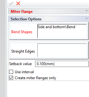
Please post the ICS and also add a sketch as to how you want the bend/s changed and I'll have a go at it. But Spencer's right - it takes bugger all time to make a new box with mitre tool ( unless the box is complex ) If you use 'Add stock' onto bends, then you limit your chances to change when using Mitre Flange or any flange for that matter. Here's the toggle in the mitre flange tool that Spencer was talking about. That needs careful thought when designing boxes.

-
I voted Perspective on. Sheet-metal and engineering fabrication design industry. My colleague who sits next to me in the office is 100% perspective OFF so when we try and work on each other's screen we have to make the change to make it work for us. Even when I was drafting by hand in the mid 60's on, isometric always felt alien to me and I never liked it. In fact, I even made up perspective backing sheets I could trace over to make my 3D models look decent ( in my opinion ). And no, there's nothing wrong with my eyesight. I just had it checked the other day and am still in the top 2% of the country's population in terms of 20/20 vision. Seems designing in perspective makes me the odd one out
-
Hi RJ. Are you meaning the scroll casing when you talk about the curve? Harley
-

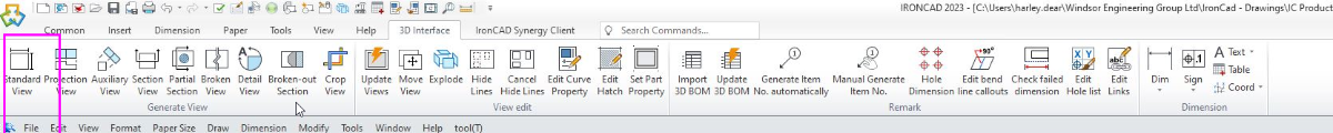
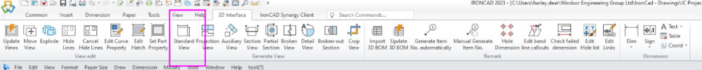
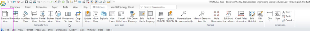
CAXA - 3D interface menu keeps changing position
HDEAR replied to HDEAR's topic in General Discussion
Thanks Kevin. Is there a "yet" to go on the end of your sentence? That would provide some hope -
Hi IC Team, I have brought this up before. The CAXA 3D interface menu keeps changing around - it's quite annoying to say the least. Has there been a bug filed for this previous? Harley
-
Combining Images, 2D Geometry and Generated Views (CAXA)
HDEAR replied to Malcolm Crowe's topic in Tips and Tricks
Hi Kim. Yes, but some of us old farts were brought up with the British Imperial system until the country metricated between 1967 and 1974 ( last stage was road distances going from miles to kilometers in 1974 ). That makes us multi-lingual Harley -
Finally! My Easter Holiday structured part training projects DONE! Thanks all Harley
-
Thanks Malcolm, Those sneaky little arrows aye! Didn't think to even look for those. Much appreciated. Harley
-
Structured part - can't get sketch to lock to 3 points
HDEAR replied to HDEAR's topic in General Discussion
Thanks Malcolm. I found another work around between posts. If you refer to my video about the surface loft not working, you'll see by drawing a line in the Rib Loft 1, using that line point as a reference for the 90 and 270 degree and then turning that line into construction afterward. I think your last method works best though as it is the least amount of work. Harley -
Thanks Malcolm. I knew there'd be a 'trick' to it.
-
Structured part - can't get sketch to lock to 3 points
HDEAR replied to HDEAR's topic in General Discussion
Thanks guys, refer my next post where I managed a work around by drawing a line and using the point to complete a 3 position sketch. However I ran into another road block when it came to surface loft. -
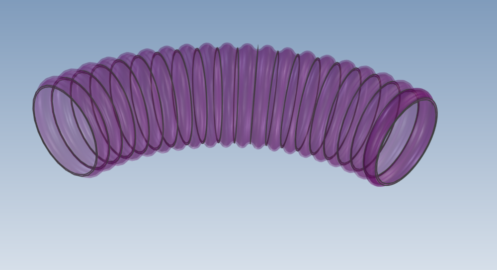
Hi all, Following on from my previous post where I had a problem with 3 point positioning of sketch. Refer attached video. I managed to get a 3 point sketch position by drawing a line in the Rib loft path 1, and using that point to do the positioning. After I had completed my 90 degree and 270 degree sketches, I made the line that I had drawn in Rib loft 1 into construction. Then when I tried to carry out a surface loft, I could not get it to work. It looked ready to work at point 3, but failed miserably after that. I've tried various ways to get it to work but to no avail. Harley Flex hose surface loft failure.mp4 Flexible hose HD exercise.ics
-
Hi all, Just making up a flexible hose a la Malcolm's videos and examples. I can't get the sketch to lock into the three positions - see video. Harley Can't select point for sketch 3 point positioning.mp4 Flexible hose HD exercise.ics
-
My mistake Kevin, he was using IC2021 but here's the part fromm his video, Constrain and extend.mp4
-
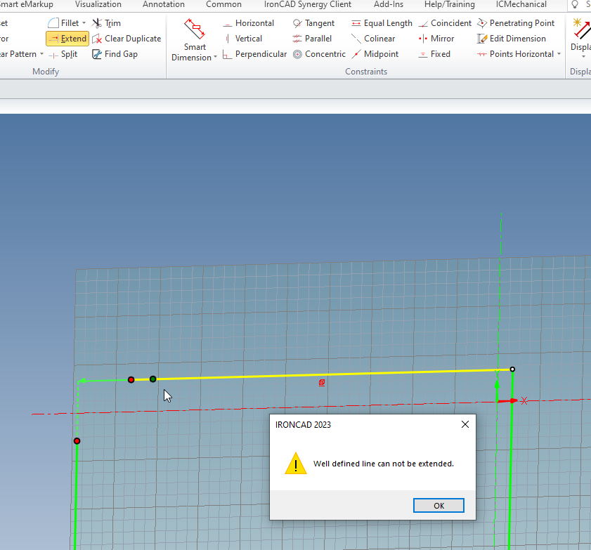
Thanks Kevin. According to Malcolm's video using IC2022, he was able to use extend in that video and I can't use extend using IC2023.
-
Also seems to be a bug on the Extend for the Sketch as well when using the project/Constrain. Or have I done something wrong?

-
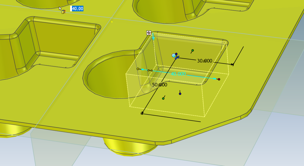
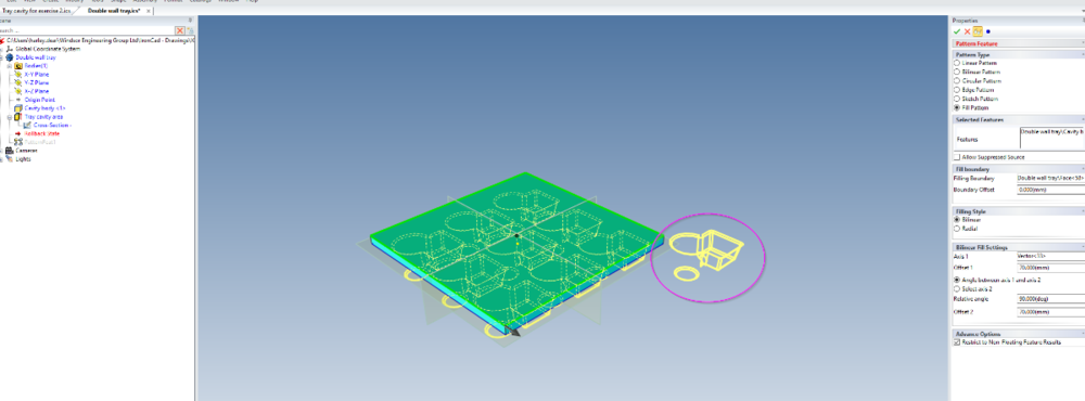
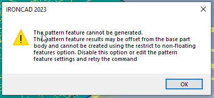
Carrying on from the previous structured part pattern problems, when I place my second wall cut-out pattern in the opposite direction, the 'up to surface' feature of the sidewall cutout is ignored and an error message occurs. Pattern woes.mp4 Double wall tray.ics
-
Pattern feature in structured part giving grief
HDEAR replied to HDEAR's topic in General Discussion
Actually, the spinning wheel of death finally goes away and you can edit the feature, so it's no longer freezing. Still, there's something not right caused by that Pattern feature failure @IronKevin Thanks for logging the bug. Much appreciated. Harley -
Pattern feature in structured part giving grief
HDEAR replied to HDEAR's topic in General Discussion
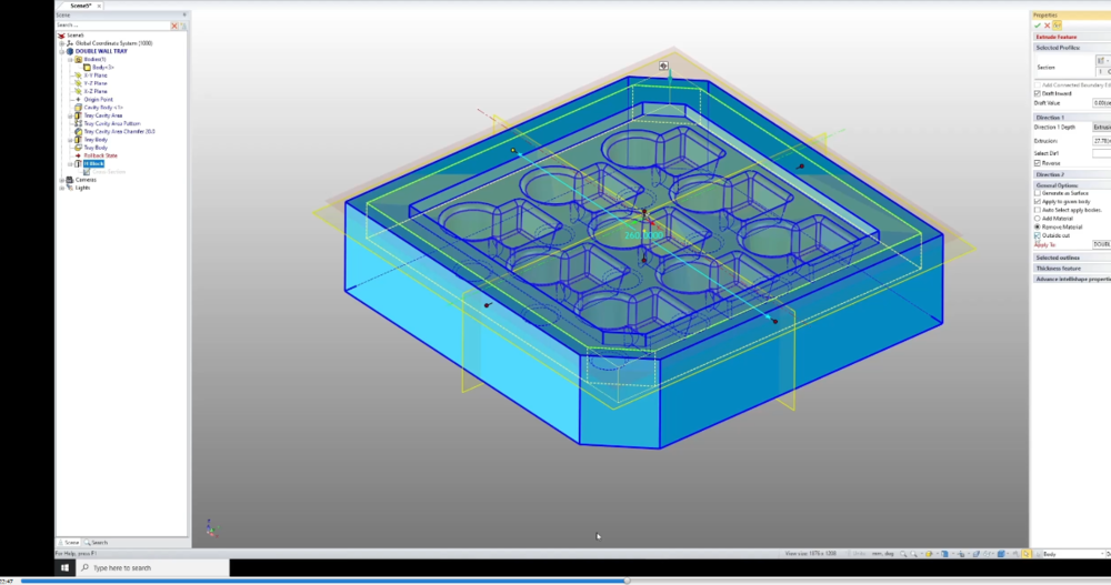
Thanks Malcolm, I thought for a minute that when I constructed the original tray to make the STP file that having the Constraint for Features enabled, that's what caused the problem. However when I killed these dimensions and re-created the STP, it made no difference. You'll find that when you get to the step in your video where you modify the extrude cut to an outside cut - the system freezes as soon as you hit Edit Features, and you cannot go any further. Even with the cut extrusion having and inside and outside boundary, Edit features freezes. MAJOR bug I'd say! Darn - I was wanting to finish this project.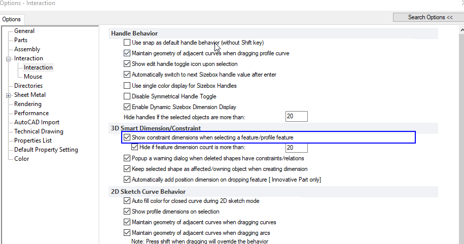
-
Hi all, I'm following a video lesson of Malcolm's for the structured part Tray - session 2. The pattern feature is giving me some grief. It seems to be adding an extra pattern to the outside of the fill area and gives me an error when I click OK. I'm doing something wrong but can't figure out what it is. Any clues anybody? Harley Double wall tray.ics
-
Hi Yeo, There's already a recent thread about this
-
Hi Tom, that's an amazing piece of work there. That would have taken a while to do I am betting. Did you do a Boolean subtract with those profiles? Harley
-
Here's a video with notes. I edited the note to add the deletion of the side bend before adding stock. Anyhow, the video should give you an idea. Also I only labelled one finished part - you should really label as you go because it can get confusing. Harley Westfalia bin.mp4 Westfalia bins.txt Westfalia Bins.ics
-
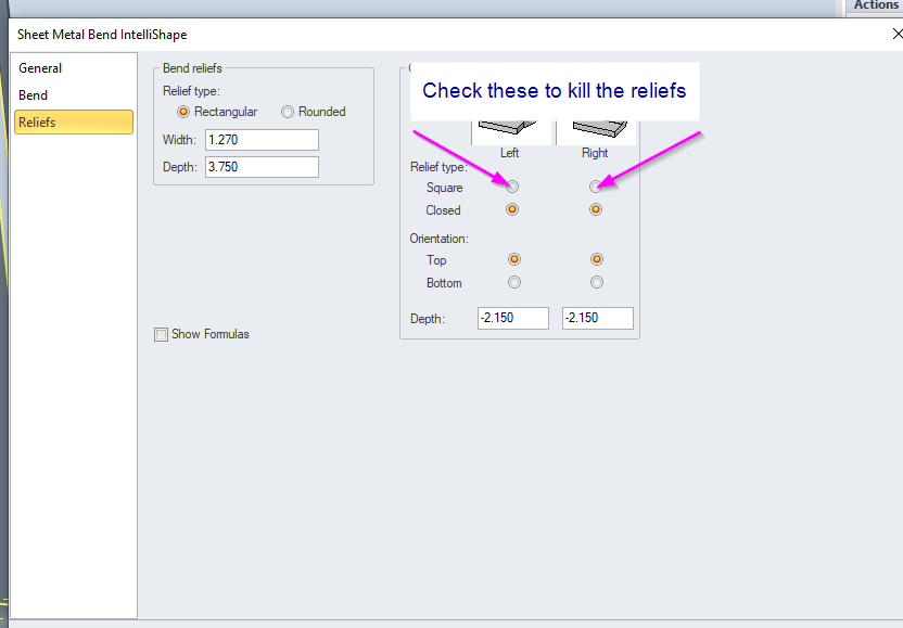
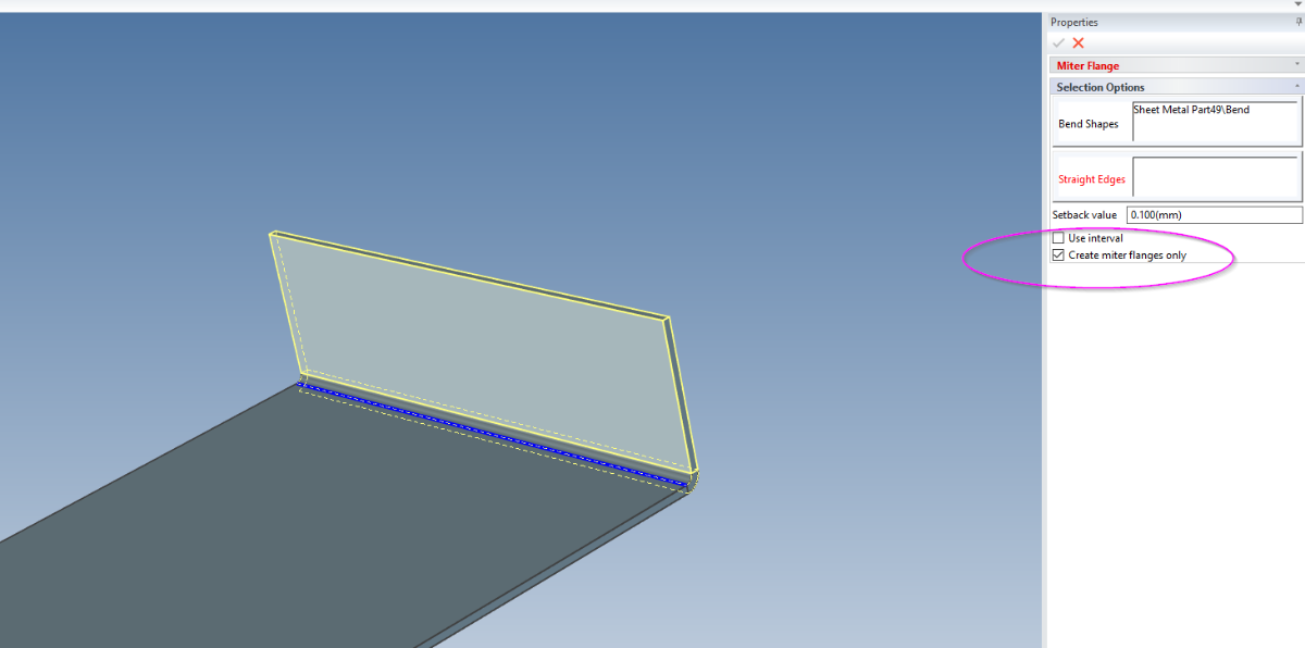
Here you go, First trick is to NOT use out bends - use smooth bends. use your maths to work out sheet sizes deducting thicknesses and bend radii. 2nd trick is to create all the mitres from the finished bottom sheet size BUT check the create mitre flnages only Make the whole assembly THEN make two copies of that. On the original, copy delete all the end and the rear side bends. Also delete the corner reliefs so the bend is parallel On the other copies delete the bends you don't want. Move them into position and extend the bottom sheet to make up for the reliefs you deleted. If you look at my model you'll see where I deleted bends and then added stock. Then you can change the sheet sizes to match and your top mitres will follow into position. It took about 3 minutes Westfalia wash bins welded.ics