Mike Hatch
-
Posts
162 -
Joined
-
Last visited
Content Type
Profiles
Forums
Blogs
Downloads
Articles
Gallery
Everything posted by Mike Hatch
-
The problem is you have to go through a process of de-selection and re-selection to get to where you want to be, rather than being able to select straight away. Is there not some way of the system knowing or figuring out that when it places the sizebox it will cover up the handles for itself or another axis, and then place it so that it does not.
-
Seen a few spams and suspect posts on the forums recently from new members with no history. Can new members have their first say, five, posts moderated to stop these "drive-bys" ?
-
I agree with several of your findings - 4. I do find the angle dimension a bit haphazard in what it will allow you to select. 5. The automated tool to reattach dimensions can sometimes completely miss, and mangled dimensions result. For our drawings I do find it does work better with the match range set to 0.01 not the default 0.001. Individual dimensions can have their attachment points edited back to the correct positions though, but occasionally i do find it quicker just to delete the dimension and place new one. 6. Yes, hole centers just disappear, sometimes jut one or more, they have to be replaced. If this happens with a view update and its a dimension to a hole center that disconnects, if you replace the center first the automated tool will usually find it.
-
Amazing IC support during Wuhan Flu lockdown
Mike Hatch replied to HDEAR's topic in General Discussion
Most certainly agree HDEAR, great help and community. Keep safe. -
The Chinese characters I've seen before, not often, but not the save external problem. Usually it pops up for me when editing catalog entries where the path gets displayed in full with that Chinese ending. Correcting the file name manually sorts out the problem, I then restart IC just in case. Have you set backup in Options ? I've not been to impressed with the backup so have got into a habit of regular "file save as" appending a -1, -2, etc, got me out of trouble once or twice. Sorry, not much help.
-
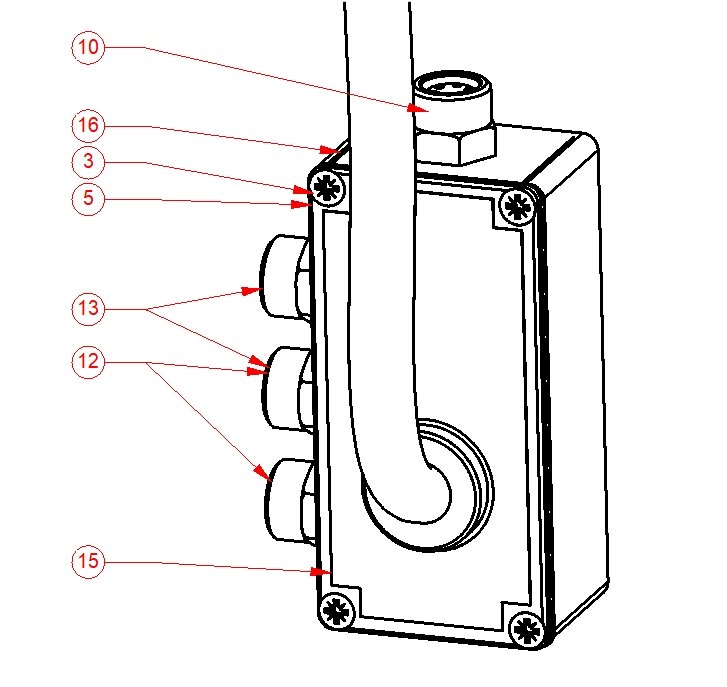
When modifying item details for a BOM table it appears that on doing an "update" to the table, the table seems to re-order the contents rather spuriously, occasionally adding new items at the bottom of the table, and at other times somewhere else within the table. Our guys checking the drawings find this a bit tedious. I know the table can be sorted buy item #; part #; quantity and description, but for a plain vanilla table in item # order is there a way to keep the sequence, I.E. new parts are added at the end, or deleted parts just shuffle up the ones below it up, rather like the way Excel does it. Also for a sorted list, if an "update" is done the list needs to be re-sorted, again tedious.
-
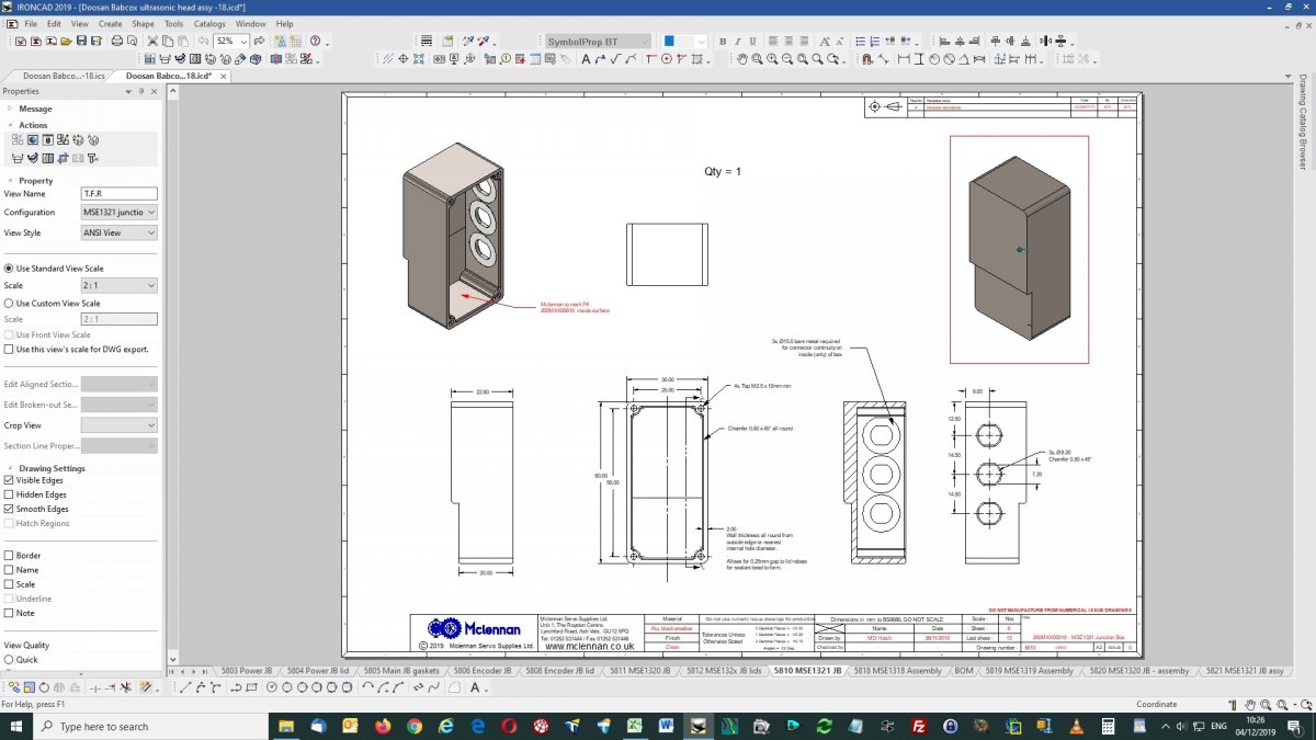
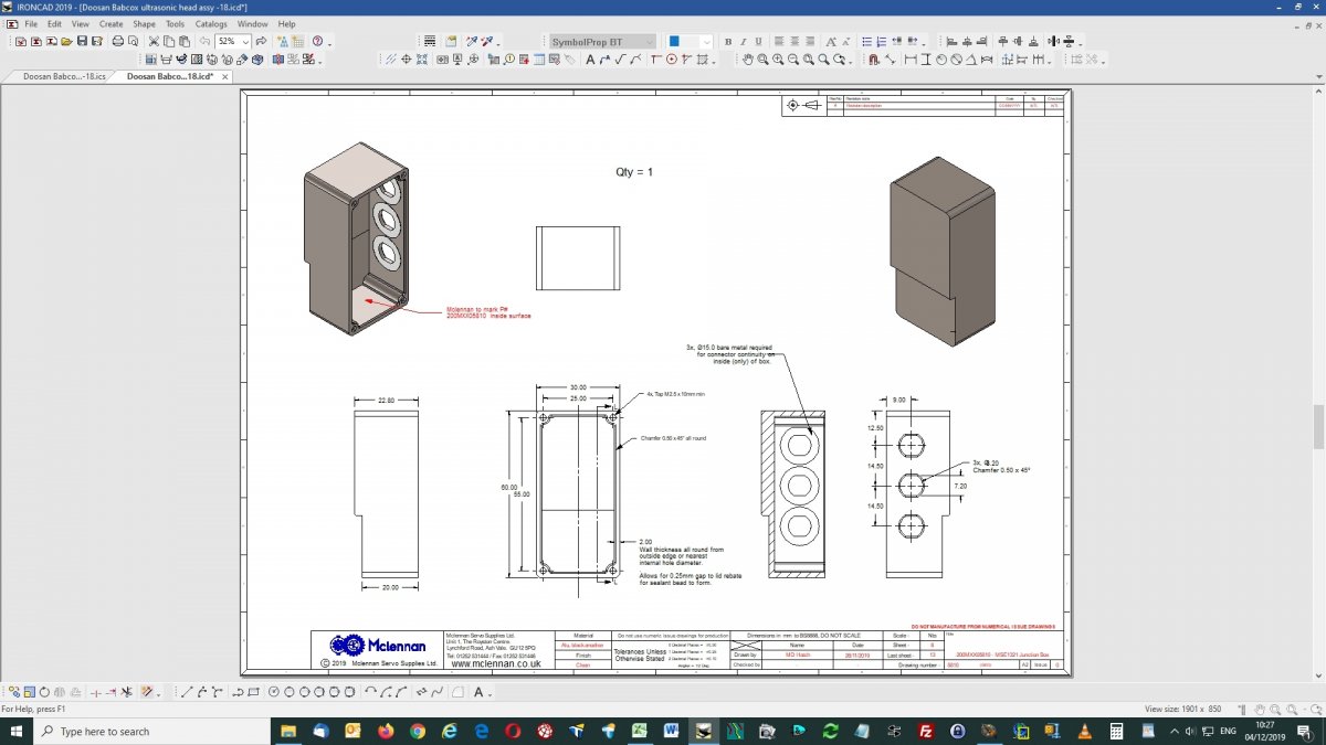
The view and the BOM are "disconnected", it can see the top left assy, but not the rest. If your view has "shaded rendering" turned on, the view will not update correctly depending on the view quality in the view's properties, turn the rendering off until you are finished whilst you go through the add bubble and update process. At the point of turning the rendering off you should see the view update automatically, hopefully the bubbles should resolve. Another point I've found that sometimes sends it screwy is when a part is set to "expand", or "set to part" where it cannot find the parts you want to bubble. Can you post the .ics and .icd files for that view to look at ? (stripped of company info if needed). Also see my post - with the comment at the bottom of "Shaded rendering not updating". Also watch out for item bubbles with more than one leader line, as the second leader line can be dragged to item not associated with the bubble.
-
That was another way that did not occur to me Doug, would still be interested to know why that right hand edge caused the problem though.
-
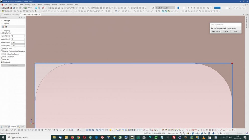
Deleting the affected rectangle, re-drawing it solved the problem, although I'm confused as to what it might have been, but I presume it would be with the original DXF, can you post that file ? Deleting the corner blends and extending the edges, once, seems to suggest the right hand edge is not placed correctly (red dots), left hand edge is OK (white dot). Delete both right edge blends, extend the corners to fit (white dots), re-blend to R30mm, the extrusion will complete correctly. Now pretty sure its in the original DXF or the way it imported.
-
Is there a way of stopping BOM's randomly altering the order when an "update" is done ?. Ideally it would be nice if the BOM just added new parts at the end of the table, however it seems to completely reorder it. If I want to "sort" later that fine, that was my choice. For a large assembly with a multi-drawing set, previous views can have their item bubbles completely re-ordered if a new view is added with new parts, and you might not remember that previous views from several years ago have also to be reprinted. Item bubbles to differing parts. Once an item bubble is placed, the end arrow can then be moved to a different item without it updating. I know the view can be "updated" later, but perhaps the update could be checked when the bubble arrow is placed. This can lead to the following situation - #12 & #13 point to differing parts, in this instance doing an "update" later does not resolve bubbles #12 or #13, it just stays the same. Shaded rendering not updating This has been mentioned before, views with shaded rendering set to "draft" will not update, those set to "quick" will. To update a "draft" view shaded rendering has to be turned off. As we usually have shaded views this is a right p.i.t.a.
-
I know its an old post, but I eventually found out (and forgot to reply) that the "blank" rows usually are for the item in the BOM immediately before the blank line. It's usually a part set to "expand" rather than "treat as part", but not always. The Scene quick search facility is also useful in drilling down to these parts.
-
Hi, We output pdf's with PDFcreator (https://www.pdfforge.org/pdfcreator) from the menu File - print. Exporting pdfs with "use individual view settings" would appear to give the same result. Exporting with "forced true representation" sets the shaded render view to outline, generates the pdf, and reverts to shaded render, not what we want. See attached files. 5803-c - exported from ic with use individual view settings.pdf 5803-c - printed with pdfcreator.pdf 5803-c - exported from ic with forced true representation.PDF
-
Thanks Cary, the failing curve (#2) was a modified version of #1 with points added by "insert point", redrawing it picking points along the way cured it.
-
If there is one thing we have troubles with its sweeps along a 3D curve, as an example see attached file. 2D Profile1 - sweeps along its curve. 2D Profile2 - does not ?, eventually ending up with a large block and error "path may be too tightly curved or a cross section too large". Profile 2 is the required path of a cable within an assembly, Profile1 a test, the only thing I can get to work. Scene1sweep.ics
-
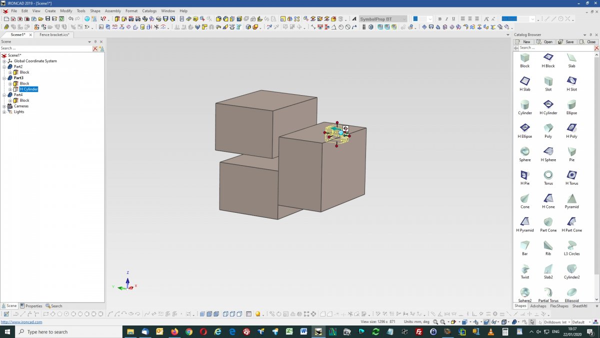
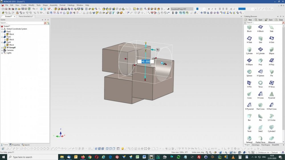
Thanks Spencer, it worked, but I had an anomaly (?) at the point of dropping an H Cylinder - Rclick drag - "Drop As Assembly Feature" - I get a 40mm x 50mm cylinder. Lclick drag - I get a 8mm x 10mm cylinder. Just wondering why I get differing sized cylinders when dropping onto the same point ? where as you don't seem to on the video.

-
Left click drag & drop, or right click copy & paste, either way works for me.
-
Hi, the design files are very large (>180Mb) and proprietary with restricted access and have also changed from customer requirements, I'll see if I can cut them down and anonymize them first.
-
A new configuration will assume the settings of the current displayed configuration. So select your "alternative configuration" with its suppressions from the "Active configuration" drop down in the bottom right hand corner, so that it is displayed. Next create a "new" configuration from the "Configurations" drop down beside it, the new one will now be displayed and have the settings of the "alternative configuration". Now change the suppressed items in this "new" to match your needs. It has been suggested that a "Suppress Selected" and "Suppress Unselected" be added to the right click options of part and assemblies to make the Suppress options more like the Hide options, not sure if this has made it into IC2020 though.
-
Not sure if this is related but I do know you have to be very particular about a parts "Part Properties" and "Assembly Properties" with the "Include this shape in BOM" and the "Assembly Expansion in BOM" selectors, if these are askew then large BOM's with many empty rows can result, and tracking them down can be tedious. I have found that the part above the first block of empty rows can usually be the culprit. We recently had an assembly from a customer with thousands of Brep1's all set to "include in BOM", the BOM table was huge for a dozen or so actual parts.
-
Do you have example files ?
-
We find that printed drawings from .ICD (to an A3 OKI 8800, or to pdf files with PDFcreator), seem to suffer with some anomalies with shaded render views. When printed various surfaces of shaded render view appear see through. Attached files have screen grabs of the page on screen, a print preview grab (both as expected) and a pdf file print, printed pages are the same as the pdf files (both mangled). The result is the same if the shaded render view property is set to draft or quick or differing scales are used. Running on - IC V21, PU1, SP1 - DELL3620 64-bit, Xeon 3.5GHz, 16Gb ram, Win 10 pro, Nvidia Quadro M2000 graphics. IronKevin - ics and icd files available commercial in confidence. On screen - Print preview - Printed result - pdfprint_x.pdf

-
Where are you ? I would recommend ours in the UK if that's the area, otherwise one of the admins should be able to advise. Is it not available on-line ?
-
That seem to have got it, many thanks.
-
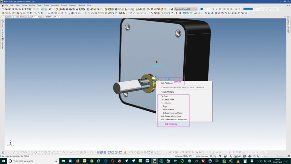
Yes same with me, using the triball the anchor does not move to the point selected. None of the options given below "create multiple" (to point, to center point, etc) end up where I select them to be. It does if I drag the triball center or edit the position.
-
Smart Paint - Identifying Existing and Removing Colour
Mike Hatch replied to SKELLY's topic in Tips and Tricks
Well if you are quick enough "undo" will remove an applied smart paint. To find the applied smart paint select the item to the point it goes blue, right click, select SmartPaint. The colour selected will be in the "Solid colour" box, if its an image it will be in the "Image Texture" box, with the path to the image file below. If you just want to copy or change an applied image or colour to something else, the "Fill EyeDropper" and "Apply EyeDropper" from the menus or ribbon bar will do that for you. You can apply smart paints on a surface level rather than part. Select the part to the point a surface goes green, then apply the smartpaint to individual surfaces. Unless I'm missing something I don't think there is a "remove" method to smartpaint, could be a useful addition, been there etc.... I normally temporarily place another part, and use the eyedroppers to return the incorrectly painted back to its default. Other methods anyone ?