


Jonas@Solidmakarna
-
Posts
2,287 -
Joined
-
Last visited
Content Type
Profiles
Forums
Blogs
Downloads
Articles
Gallery
Everything posted by Jonas@Solidmakarna
-
Even without the video, based on the fact that the option "auto-associate to attached entity" at the bottom of your image only works for (from catalog) dropped items and not copied with the TriBall, as you've probably done? I'm afraid that's why it doesn't work. I might be wrong, but I don't think it has ever been that way. There are many things that (can) happen when items are dropped from a catalog. When a face/edge/vertex lights up in green some kind of association is usually created, more or less rigid. Compared with a TriBall copy where no association is (ever?) created. For example, compare a TriBall Mirror Linked copy with the Mirror Feature or a TriBall Pattern with the Pattern Feature - very similar in result but very different in structure and function.
-
Can Dimensions / Smart Dimensions "drive" part size?
Jonas@Solidmakarna replied to Macktek's topic in General Discussion
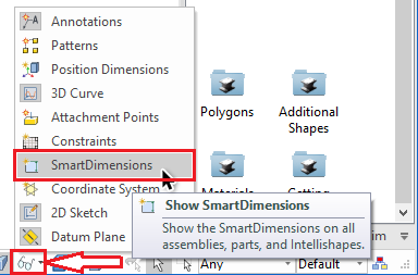
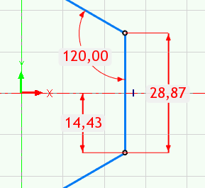
Hi Macktek, First, I think you should have a look at the basic training material available online. It will answer most of the questions you don't yet know that you have! https://www.ironcad.academy/tutorial/training-01 The Smart Dimension tools that you have found are mainly used for positioning objects in 3D space. Not for manipulating/driving the size and shapes of them, just as you guessed. Btw, you can toggle the visibility of the Smart Dimensions with the glasses at the bottom: The red handles found directly on the shapes (another click with the left mouse button after the blue edges) are the tools you are supposed to use for changing their dimensions. So if you use the Smart Dimension tool to place a dimension between two points/sides of the same assembly/part/feature, it is "only a visual dimension". It won't do anything else (like modifying). You can see the shapes dropped from the catalogs as schematic in one way. They are made to be modified only to keep their individual shape, where a block is a block, a cylinder is a cylinder and a polygon is a polygon (though the number of sides can be modified). The red round Sizebox handles on the Intellishape level will scale the models and still keep their "relative shape" intact. If you want shapes that have another kind of rule or shape, you must make them yourself from start. Use the Extrude tool or edit the Cross-Section of an existing Extrude feature (Block, Cylinder or Polygon). If the shape should be defined by some kind of "rule" (like in parametric control) you must add those rules yourself. Rules are mainly defined in the Sketch/Cross-Section by Smart Dimension Constraints. Just like in any parametric CAD system you must (probably) make the curves "fully defined" (green color on curves, instead of the blue "under-defined" color) in order to follow your expectations. As Malcolm said, the thing with IRONCAD is that you don't really need to add constraints to get things done. Most kinds of parts are easier to manipulate using the red handles (which in turns will manipulate the blue "under-defined" sketch geometry), because it is much faster to find (snap to) values with the help of other geometry in the scene. Only when you want to edit assemblies and parts like bearing houses, steel profiles and other "table controlled" types of parts, then the need of adding rules might be useful.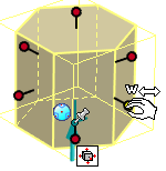
-
Sharing Scene Color Settings with others?
Jonas@Solidmakarna replied to tlehnhaeuser's topic in General Discussion
The colors are managed under the general IC Options, which are stored in the registry. You could export the CURRENT USER registry settings and send them to the user. If he has made an export of his own first, he could revert back to those settings afterwards. HKEY_CURRENT_USER\Software\IronCAD\IRONCAD 22.0\Color Be aware that altering the registry might stop things from working as they should. In this case, you can actually remove the IRONCAD 22.0 folder without any issues, because it will be restored on the next start of IC. It is one way of "resetting" the system when you have strange issues. -
Finding the offender - 'at least one surface or shape...'
Jonas@Solidmakarna replied to HDEAR's topic in General Discussion
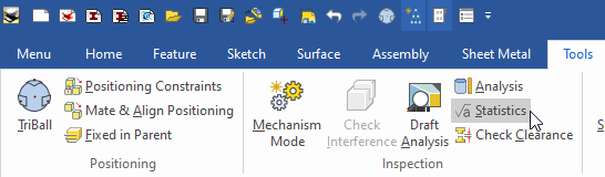
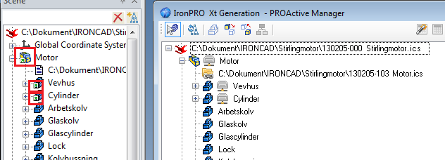
The Section Tool in the drawing cannot section surface parts. Finding them can be done manually by expanding the tree items and visually looking for the orange surface part icons. You can also use the IPRO Active Manager tool in the IC Mech Tools catalog to divide the tree into different types and find the surface parts that way: You have probably imported a STEP file which contains one or more surface parts. But it can also be a part which contains negative features that touch each other in a way that the Parasolid kernel doesn't handle. Those kind of parts can be found by running the Statistics tool under the Tools tab. Make sure to select all (or selected) parts from the scene first.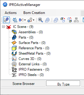
-
What causes this weird problem in sheet metal bends?
Jonas@Solidmakarna replied to HDEAR's topic in General Discussion
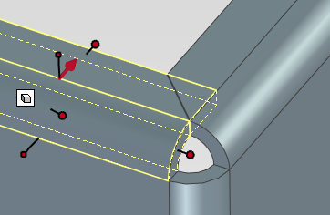
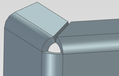
Hi Harley, Have you tried the Miter Flange tool? Just select the Bend on one side, then select the edge to miter with. The Miter Flange feature will still contain the first bend, which can be modified and the Miter updates. You can also choose to create the other Bend individually by selecting the "Create miter flanges only".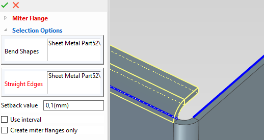
-
Spacemouse twitchy when close-up
Jonas@Solidmakarna replied to Kim@AITECH's topic in General Discussion
I heard from a user that the SpacePilot will work for Windows 10 if you use the old driver 10.4.3 -
Yes, I meet a lot of new IRONCAD users that has been working more or less with an "only parametric" system and it takes some time and some frustration to oversee the differences. A comment that I recently heard was that "I was first very frustrated and went home (after the first day at work with IRONCAD) very depressed and angry. But, as when I was in my bed that evening, I came to think about the other guys here at work. They have designed and manufactured very advanced and complex machines and I understood that it can't be the system, it must be me! So, the next day I just decided to let go of all the previous knowledge (trust me, it wasn't easy!) and accept that it is different. After a few days (and some training videos) I was up and running and now a few months later I think I'm really getting the hang of it!". What is really interesting with IC as that you can choose for yourself wether you want or relly need constraints (usually you don't!), not because the system demands it to actually work - but because you see the need yourself. When you've learned the basic tools in IC and see the benefits, you will only use parameters and constraints for certain kind of models. But the first period of time can be tough and I hope that you can see that you will become productive quite soon.
-
I think the current HP, Dell, Lenovo etc workstations are working really well. Yes, maybe a few (or many) more bucks, but quite reliable in general. I've been using a HP Zbook 15 laptop for a few years now and it is really good. Just remember to deactivate the integrated Intel HD graphics in them and you'll be fine. Having a fast SSD and CPU are probably the most important things. I have no hard facts on using Xeon vs. Intel i7 (or i9), but the Xeon also comes with a "special" Windows 10 OS named Window 10 for Workstations. I think it uses the RAM in a better way and has more space for really large amounts of RAM (which is good for FEA calculations), but I haven't been able to try it out myself. Graphics. I would like to do some tests on Quadro vs. GeForce! The Geforce RTX cards are really good. Now the Quadro recently also came with an RTX version which sounds like a real work horse.
-
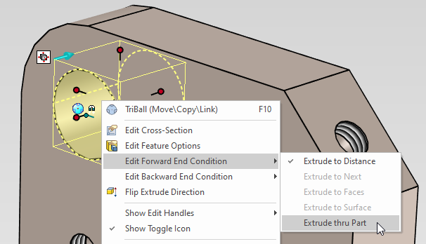
When you [Shift] snap a red round Sizebox handle to another face (lights up in green) you do not create a relation/constraint. Instead that process (snap) will "only" create a number for the extrude to stop at, nothing more. This is a basic and important part of IRONCAD, the numbers you set will never change "automatically". For me this is crucial and I trust the system on this. However, If you want to set these kinds of relations you can do it in several different ways. For an extrude to go all the way through the part you can right click on the extrude feature (which might be an H Block) and set the "Forward End Condition" to go through the whole part. I think it is also important to know and understand that the reason why we don't want to use constraints and relations is because there are other types of tools and workflows in IRONCAD which doesn't exist in other 3D CAD systems! "Automatic" means "a rule that someone has decided" and you usually cannot bypass this in an easy way. By skipping this "automatics" and using manual tools (which are really fast) you have more control!
-
A couple of issues or new behaviors that have showed up connected to new functions on the SmartDimension tool in the ICD. I don't know if these are related, but they might be. A ) If you have long objects and large scale (1:100, 1:200 and more) the dimension text can be placed far off the sheet and you must zoom out/in quite much and often, to place it where you want. I think this is due to the dimension text and the mouse cursor that is automatically moved to the "center" between the points that you dimension. If the mouse cursor wouldn't always move to the center of the dimension, it would probably "feel" better? B ) The Unlock Dimension Text function (also U key on the keyboard while placing the dimension) is another of these "automatically move dimension text and mouse cursor" functions that you might not be aware of and which can be unwanted.
-
I've been using the Greenshot a few years now and I really like it. Since I do a lot of explanatory images and use these small images in various documents and e-mails, I want more control than what the Windows Snipping tool gives me. https://getgreenshot.org/ I got a great tip from a friend the other day about PicPick, which is very similar and maybe have some other benefits. https://picpick.app/en/
-
Hi, Try using INT in the Expression, for example to change the quantity (Scalar) in a Pattern. INT( (ALR / RBPD) ) Where ALR is the Assembly Length Read (which uses the expression Sizebox\Length) divided with RBPD (Round Bar Pattern Distance (=c-c distance between the pattern instances of rods)). Without INT the result could have many decimals, but now it gives an integer value. Here's an IC Catalog with parametric models that I've made for training, though it uses mostly Swedish comments and Parameter Names. ParametriskaModeller2019.icc
-
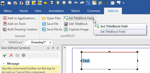
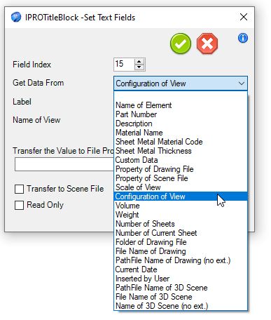
This can be done with the IC Mechanical / IronPRO XT functions for textboxes. You can show/transfer quite many values which are not supported within the ICD itself (yet). Have a look under the Add-Ins ribbon tab, in case you've installed the IC Mechanical tools.
-
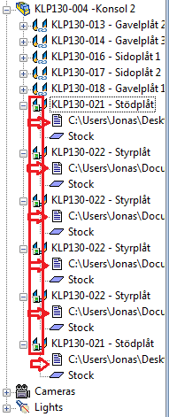
Hi Will, When there are multiple instances of an externally linked Part or Assembly, the Scene Browser icon is incorrect. It should show the "chain link" symbol, but shows the same icon as for internal links - Incident ID#: 107576 There's also an old ER to show this information more clear in the Scene Browser, just as the PROActiveManager of IronCAD Mechanical already does - Incident ID#: 102639
-
Hi Oil, Please contact Solidmakarna for Swedish support on IronPRO XT. https://www.solidmakarna.se/support/
-
I would strongly recommend you to disable the integrated Intel graphics chip under the BIOS settings. It isn't even sure the driver settings really work, because it seems like Windows steers the graphics to always use the Intel graphics and not your dedicated (or discrete graphics, as HP calls it) graphics card, no matter what settings you think you are using. I'm not confident about this, it is more of a "feeling". Though one large and well known CAD developer has recently "certified" the Integrated Intel graphics, which lead to a local HP reseller having to always manually disable the Intel graphics, to be sure their machines work as their customer would expect. I've talked with 4-5 users running brand new Dell Precision laptops the last few weeks and on a couple of them (one was a 7530 with Quadro P320) the Nvidia graphics was actually disabled under BIOS from scratch!
-
Separating Part Features into Separate Parts
Jonas@Solidmakarna replied to Malcolm Crowe's topic in Tips and Tricks
Another option is to use the IronCAD Mechanical tool Split Intellishapes. http://www.ironcad.it/en/manuale/split-intellishapes Remember that splitting features to a new part with this tool will also create a new part having new ID numbers for each Face, Edge, Vertex of that new part. This means that features such as Blend/Chamfer/Shell etc, which are based on those ID's, probably cannot "survive" this kind of "castling". In those cases I would always go for option 1 described by Malcom, since it is very stable and predictable! -
I'm glad you like it! Here are two more: Chequered Plate Five Bar Chequered Plate Rice Bar
-
Find Cross-section problems?
Jonas@Solidmakarna replied to tlehnhaeuser's topic in General Discussion
I always search for these possible issues: ¤ Overlapping Curves Remove by using the Clear Duplicate tool. ¤ Crossing Curves Highlighted in purple when you Finish. ¤ Red dots 1 = Open Outlines Outlines must be connected = white "knee points". ¤ Red/White dots 2 = Zero-length Curves - the hardest ones to find! Select the outline, Cut (or copy). Then Select All (easiest by hitting [Ctrl] [A]). Delete everything. Then Paste back your outline. -
Opposite effect on lengthening handles
Jonas@Solidmakarna replied to HDEAR's topic in General Discussion
I agree that the visual appearance isn't clear on the new Sizebox handle (resizing behavior) button. Opposite of what you get, kind of. What you should keep your eyes on and always look for is the "active" handles which are yellow. Remember that you can still use the [Ctrl] key to select from all the handles. Those which are yellow are "active" and will change. Ignore everything else I've heard some comments that users do not want to see the new handle, because they are used to select with the [Ctrl] key. So, similar with the new "TriBall activator" icon, can you make it possible to control the appearance On/Off? -
Problems with move and rotate in scene 2D sketch
Jonas@Solidmakarna replied to HDEAR's topic in General Discussion
Hi Harley, This is a known bug after 2019 PU1. If you start the command first, then select the curves it should work fine. I think there will be a service pack out soon, but there are already some hotfix DLLS available for us here: http://community.ironcad.com/index.php?showtopic=12942 -
I sometimes set 5, then save and load is faster =) But of course raising the value again later might be slow, at that time. Never mind the "square shaped" holes
-
Thanks! There are many different kinds of cool types of parts you can do Yes, I can repeat both those issues. 1) Editing the Sizebox of another shape will (temporarily) brake the "sync" of the two. As soon as you edit only the Sizebox of the Belt H Shape it updates and works fine. 2) Undo doesn't work on dimension change, but works fine on position change.
-
Hi Carlo, Try using the ACIS kernel instead.
-
I got a great tip by a user a while ago on a splendid "snippet tool" called Green Shot. I just have to share it, since I use it all the time! https://getgreenshot.org/
