Leaderboard


Popular Content
Showing content with the highest reputation since 04/09/2024 in Posts
-
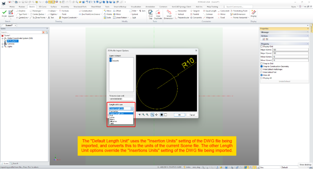
Within 2D Profiles (sketches) it's possible to import geometry from existing DWG files. Within the Import Options Dialog there is the ability to set the "Length Unit to Use". This selection relates to the source file (not the current Scene) and influences the size of the imported geometry. When the "Default Length Unit" is selected, IRONCAD uses the "Insertion Units" setting of the DWG file being imported; and converts this to the units of the current Scene file. If geometry in the DWG file has a length of 10 inches (that is, 10 units set to inches using the "Insertion Units" setting), then IRONCAD will convert the 10 inches into 254 mm (if the Scene units are set to mm). So, it helps being aware of the INSUNITS setting in DWG files. When the other Length Unit options (Centimeters, Feet, Inches, Meters, Millimeters, Yards) are selected, these override the "Insertion Units" setting of the DWG file being imported. So, if the original DWG has geometry with a length of 10 inches, but within the import options the "Length Unit" is set to millimeters, then IRONCAD will treat those original 10 inches as 10 mm instead. This is demonstrated in the attached video, where DWG files using different "Insertion Units" settings are imported into a 2D Profile (sketch). Malcolm 2D Profile Import Options - Length Unit to Use.mp4 DWG Setting - Insertion Units - Inches.dwg DWG Setting - Insertion Units - Millimeters.dwg DWG Setting - Insertion Units - Unspecified.dwg
 3 points
 -
(ATLANTA, Ga.) April 25th, 2024 – IronCAD, a leader in CAD solutions for design productivity and collaboration, is excited to announce the first product update of 2024 for its flagship CAD software. IronCAD 2024 Product Update 1 (PU1) brings significant enhancements and product quality improvements across general modeling, sheet metal design, and collaboration capabilities, designed to accelerate the design process and improve user flexibility in a multitude of engineering environments. In addition, IronCAD is excited to announce the launch of the IronCAD AI Chatbot, a revolutionary new feature designed to enhance user experience and proficiency with IronCAD software. This cutting-edge tool, powered by the latest ChatGPT 4 AI system and backed by an extensive IronCAD database, offers users comprehensive guidance, enhanced learning, and new user guidance on IronCAD’s unique design approach. Read More.. Access Product Updates at https://www.ironcad.com/product-update/2024pu1/2 points
-
i also recommend turn off Copy image data to scene file on save. After we reduced time from 1,5min to 5sec2 points
-
Dear Kim Great - thanks a lot for this! This is indeed somewhat better than what I had but still an iterative trial&error procedure with a lot of fiddling. I'm hoping/looking for a more deterministic approach (as you propose in the other thread)1 point
-
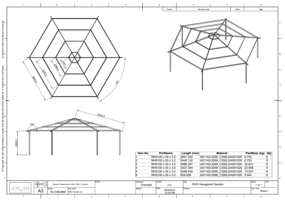
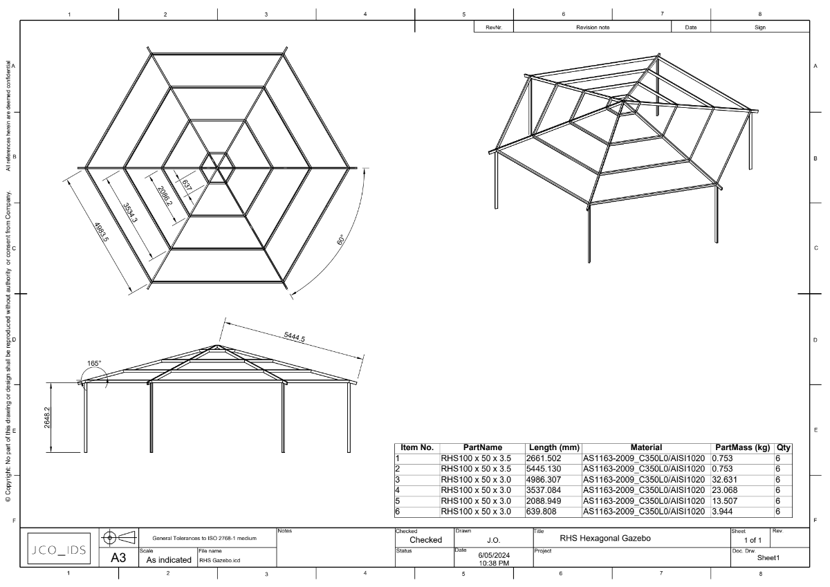
This is an option to structured frames. The StockRHS_ANZS catalog is based on Australian and New Zealand RHS sections. Hexagon Gazebo.pdf IronCAD Blue_Datum+Profile.ics RHS Gazebo.icd RHS Gazebo.ics StockRHS_ANZS©.icc
 1 point
 -
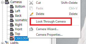
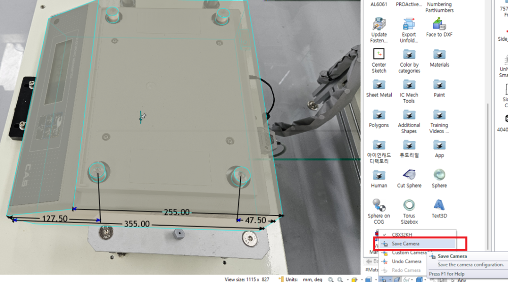
Hi Ludin, For Super Perspective Camera, you need to edit it in the camera's properties. And the "View Manager" in ICM tools that controlling View by numeric would be help for aligning the object to the picture. See the attached photo below. bandicam 2024-05-07 11-45-15-563.mp4 Did I guess it right? Edit) Don't edit the properties of the default Camera, Copy & Paste that camera and edit properties in that. Field of view angle : Zoom value Position : This is the X, Y, Z camera position that is related to the Far away~~ value of the camera wizard. Select a camera and choose Look Through Camera from the pop-up menu to change the active camera. Once you're happy with the result, be sure to save the current screen with “Save Camera” - this saves the location you are currently viewing (Camera), not the values associated with the camera properties. Kim
 1 point
 -
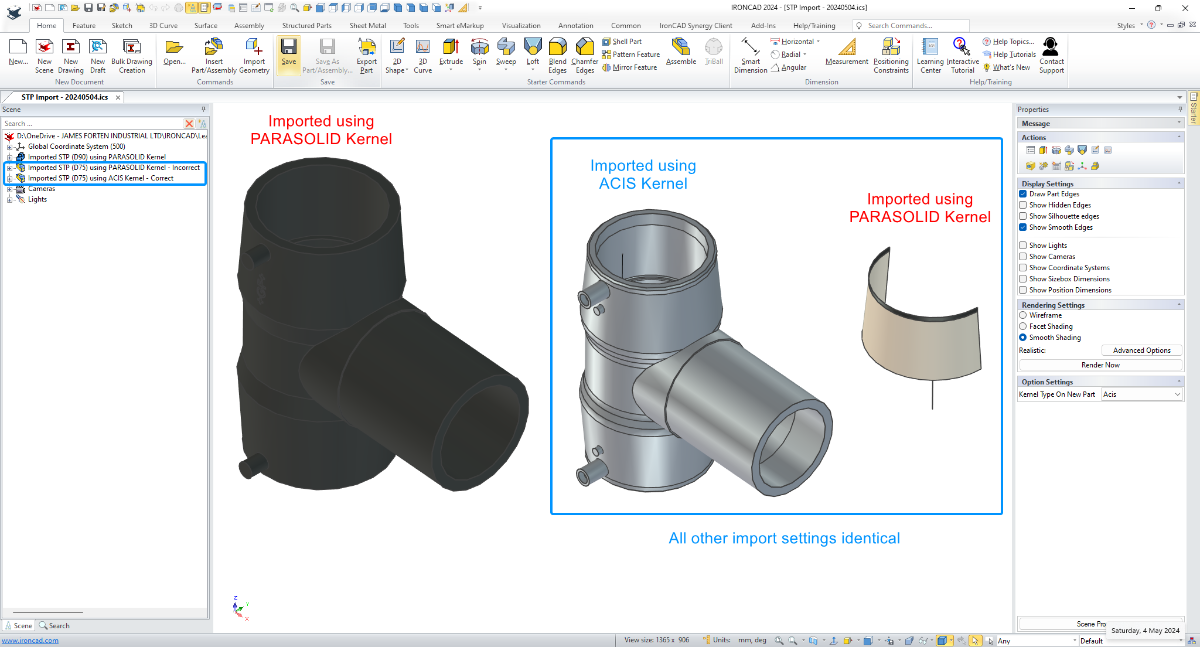
In this example I'm importing two STP files received from the same supplier. For one of these parts, it was necessary to set the Scene Kernel to ACIS for it to import correctly, whereas for the other part it imported correctly when the Scene Kernel was set to PARASOLID. So even though these came from the same supplier, the CAD software used to create or export these may have been different. Hence the different results. Malcolm STP Import - Changing Scene Kernel - 20240504.mp4
 1 point
 -
I see this too in Groups coming from IronCAD 2023. Bug report filed, QA 818601 point
-
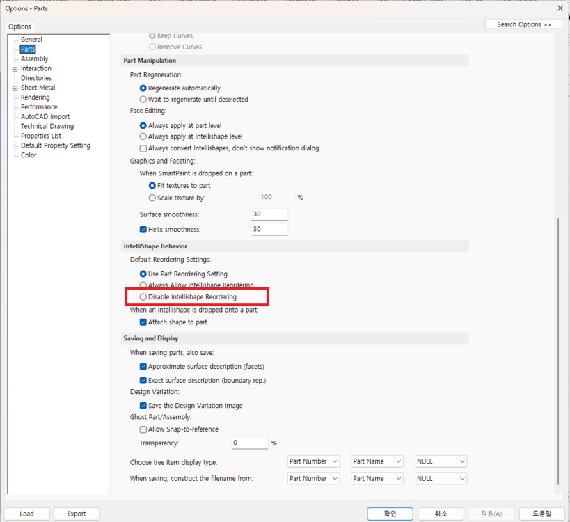
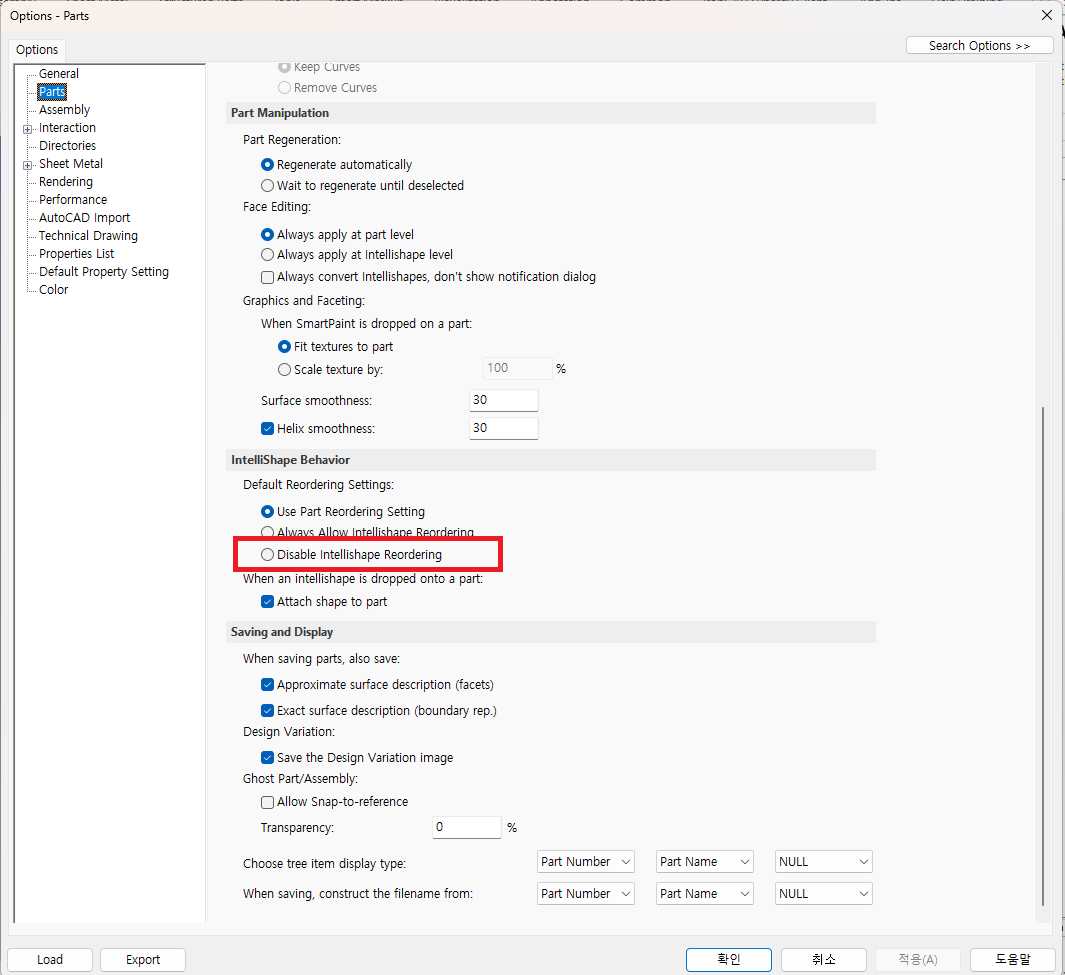
Hi, Are you finding this option?
 1 point
 -
Regarding CAXA DRAFT, if you want to reduce the amount of typing required within your 2D Drawings the attached video demonstrates the following: 1. Use "Attributes" within "Blocks" (including Drawing Frames and Title Blocks) that have selectable options. 2. Create frequently used text items as "CAXA Symbols" (special type of Block) within the "Parts Library", that you can drag-n-drop into your drawing. 3. Use "Set Matching Rule" to match the "Attributes" within your Title Block and BOMs to the Properties in the 3D Scene, so that they automatically populate. This requires that the Properties exist in the 3D Scene in the first place. See separate post regarding "Using Custom Properties List .......". Other users should feel free to add their own tips here also. Malcolm Options for Reducing the Amount of Typing Required.mp41 point
-
For those interested, attached are our updated custom settings documents for IC2024 PU1. IRONCAD DRAFT - Options - Custom Settings (2024 PU1) - 20240427.pdf IRONCAD - Options - Custom Settings (2024 PU1) - 20240426.pdf1 point
-
Hi TaeGyu, There have been positive improvements regarding Structured Frames within recent releases, and there are many potential applications for it; but in my opinion additional enhancements are needed before I'd start showcasing it to users. Perhaps some of those enhancements will arrive in IC2024 PU1 or IC2025 or ....... (I don't know what R&D are working on). In answer to your questions. 1. Sometimes I like to toggle between displaying and exporting Solids and 3D Curves (as part centerlines). This is a huge benefit offered by Structured Frames (and Structured Parts). In these applications I will include 3D Curves, but these are normally "Extracted 3D Curves" from a 2D Sketch. 2D Sketches provide better control and can be driven using parameters. While the 3D Curve tools have been greatly improved recently, they also require additional enhancements to provide the level of control needed. As a result, these aren't my preferred tools. 2. It is very rare that I need to create a Datum Plane (but I'm pleased to have the capability for when I do). You don't need Datum Planes to create 2D Sketches. For example, in your model the Datum Plane wasn't necessary, as the "Sketch Position" tools provide that positioning functionality relative to the XY, XY, and YZ Planes of the Part. 3. For some projects we export the CAXA BOM to Excel Spreadsheets for the reasons that you have listed. All of our BOM Styles contain all of the properties that we might want to display or export. But we control what is displayed in the drawing by controlling the width of the BOM item within the BOM Style. A width of zero (0) means that it doesn't display. Regardless of what is displayed in the BOM on the drawing, when the BOM is exported from CAXA, all of the columns are exported to the Excel Spreadsheet. Malcolm1 point
-
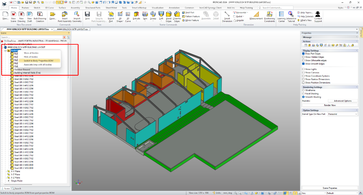
Hi TaeGyu, I'm pleased that it helped. Regarding any Application being written for extracting Part Properties from multi-bodied Structured Parts, it's important to reference the "Switch" between Part and Body Properties. This "Switch" was introduced in IC2024. It you're not familiar with this, see the attached video. Malcolm Switch Between Part and Body Properties BOM.mp4
 1 point
 -
Hi TaeGyu, In the attached video I demonstrate how to apply the requested properties (Description and Material) to the individual Frame Members (Bodies) of the 3D model, so that they then appear in the BOM of your CAXA drawing. I also show how to get the Qty to display and total correctly within the BOM. I hope this points you in the right direction. Malcolm Structured Frames - Bodies in BOM.mp4 STEEL_TEST - MC.exb STEEL_TEST - MC.ics1 point
-
What would cause a 92Mb .ics file to take over an hour to open? And is very sluggish once it opens. I had a file that started acting sluggish, not terrible but noticeable. It was a little over 300 Mb, certainly not the largest file I have had. I cleaned a bunch of junk out of the file and split it up into 2 files (as there were two major assemblies in the file). Each ended up being around 100Mb, but were still slow to open. I thought my old RAID server might be going bad so I moved the files to my computer's hard drive with no improvement. I updated all of the parts in one of the files and tried it again, no change. The file does not appear to be taxing the CPU, only about 35%. I tried opening a similar sized file and it took less than 15 sec to open. This file had quite a bit of imported data from digital sculps that had been converted to nurbs solids compared to the slow file which was mostly IC generated. Power Spec <1 yr old i7-13700KF 3.40 GHz 32 Gb RAM NVIDIA GeForce RTX 4070 12Gb GDDR6X Windows 11 Pro1 point
-
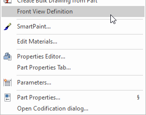
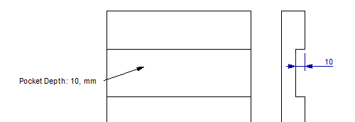
Hi Logan, Is the Panel part or the Pocket feature ever being reused? Do you create new parts and features every time, or do you use a catalog to store them or do you open old files and make the changes (then save as a new file)? If you reuse them (dropped from a catalog or save as new file) you can standardize this in several ways. There are probably more than these two. 1) Use the Smart Dimensions which are being transferred to the Drawing, like the ones that you have on the images. But as you say, I don't think you can (currently) show the dimension on the Front view. 2) Create parameters which are read as Custom Properties that are transferred to the Drawing. Then show the Custom Property info in a text block or in the BOM in the Drawing. In one way, even if it adds some clicks, this is pretty fast to to for any new feature if it saves time in the end. If this sounds interesting I can record a video later. You can control the direction of each part using the Front View Direction option on each one. Is the Drawing showing all parts in one View or do you create a View per Part in the same Sheet or do you create one View (or more) per Part in one Drawing file? Using the Bulk Drawing Creation tool could maybe save you some time here, and I think it can do any of those three choices above.
 1 point
 -
Thanks, Kevin! Triballing is underway1 point
-
Some materials: https://ironcad.academy/tutorial/positioning-constraints#assembly1 point
-
If you want to be really fancy you can bind it to a new shortcut or mouse button, but I don't even do this. I do the right click in scene browser method mentioned above.1 point
-
In case your like me and not a big fan of shortcuts, simply right click on assembly in scene or browser and see attached.
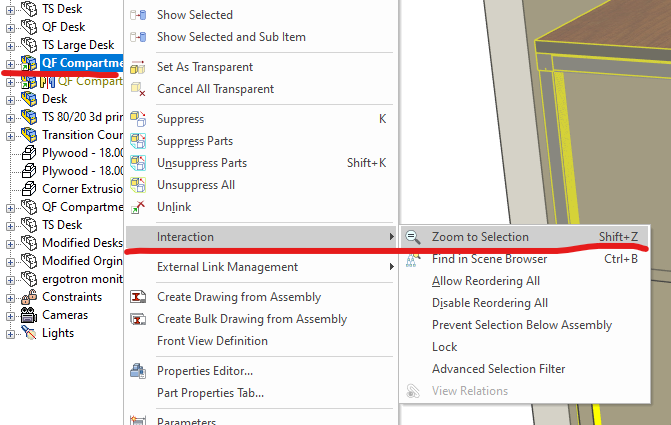 1 point
 -
Kim, you may have to recreate a rounding function. The easiest way would be INT(2 x DEGREE - INT13). Basically the idea is to take the integer of the truncated plus twice the difference of the original and truncated numbers.1 point
-
Best option is select part for example by ctrl + mouse and any time i use ctrl + b. Fast option for show in tree scene element1 point
-
Project1.rvt1 point
-
My original Engineering and Operational Management background was within high-speed Manufacturing Operations (24 hours per day, 6 days per week, and speeds up to 1,000 parts per minute). As a result, I have a very good understanding of the ingredients necessary to maximize “Productivity”. When consulting for new manufacturing clients, one of the typical questions that senior management ask is what new Plant and Machinery they need to invest in to “Increase Productivity”. More often than not, the missing ingredient that they need to invest in is “Training (Learning)” of their staff. The same is true regarding CAD productivity. The CAD software that you use is only one of the ingredients. The value of investing in expensive CAD software, add-ons, or upgrades, is greatly reduced if you don’t invest in learning how to use the capabilities they offer. You may as well have invested in far less expensive software better matched to your level of understanding and usage. So, if you've chosen to be in the design business, chosen to invest in the Hardware and the Software required, then “Choose to Invest in Training (Learning)” as well. You'll become a lot more "Productive" as a result. Malcolm
 1 point
 -
Are there any STP experts able to answer these importing and exporting questions? Malcolm0 points


.thumb.jpeg.97d1b20d295fe75f82417035aa38dd59.jpeg)