


Josh
-
Posts
56 -
Joined
-
Last visited
Content Type
Profiles
Forums
Blogs
Downloads
Articles
Gallery
Everything posted by Josh
-
@rsaucier @Malcolm Crowe I also use OBS, takes a small amount of setup at the beginning but works really great, renders in real-time so there's no waiting for a video, and seems to work well with alternate microphones. Every video I've done on the Academy was done in OBS. I've recorded at both 4K and at 2560 which is what most videos are. With the right settings, the video file sizes are also much better than Camtasia which I used in the past. Keep in mind recording at 4k is going to take up a ton of hard drive space, and probably be working your computer hard enough to slow down IronCAD operations if working on complex models. Go to Settings > Output and change your recording format to Mp4 (in my opinion) for better compatibility.
-
@cangshuMy laptop has a wacom touch screen with a pen, and I can use the pen to push and pull handles, move the TriBall (which can be a bit hard) etc. It's relatively easy to use, and can be quite fun, however I think it is probably slower than a mouse. You don't have the simplicity of the middle mouse button for rotating as an example, and right clicking can be harder. I haven't really tried to setup an efficient Pen workflow, but with some shortcut customization, and a custom menu, it could probably be made quite efficient. Note: if you are looking at a drawing tablet without a screen, I think that would make things far more difficult with IronCAD, because unlike drawing/painting, you need to specifically select onto handles/points etc. A few tips if you do go in that direction: 1. It's probably a good idea to raise the "Mouse Pick Appeture" to a higher number, this is essentially the "error tolerance" for where your mouse/pen is. So even if you miss the handle by a few mm on the screen, it will still pick it up. Maybe experiment with numbers, as too high can make it hard to select small items. You can find this setting in MENU > TOOLS > OPTIONS > GENERAL 2. Rotating the model will be painful, so you probably want to set up a shortcut key for the Orbit command, shortcut keys can be set under MENU > TOOLS > CUSTOMIZE > KEYBOARD. At the same time, there are probably other useful keyboard shortcuts to set. 3. Turn on increments. When resizing, the default behavior is to allow any size, so you might size to 100.042mm instead of 100mm. If you turn on increments, it will make it easier to hit exact numbers. However, be careful when snapping to geometry which is not an even distance away. If increments are on, and you try to snap to something that doesn't' fit the increment, the system will choose the closest increment, which can create gaps in geometry if you're not careful when snapping to things. You can change this by right click on an intellishape handle, and with the triball change it by right clicking in empty space when the triball is active. Hope that helps!
-
@C_Great to hear you enjoy the academy tutorials. Renders look great by the way! Especially the close up with the stitches. Regarding when/where to use tools, it's a very hard question because every tool has so many applications, and you can make practically anything in 10 different ways. For example, the seat "pillows" in your model could probably be done with solids and no surfacing, at least that's how I would probably approach it at first. A few different cuts and extrudes (or maybe lofts) could likely make those quite nicely. Surfacing will give you greater control over the overall shape, at the expense of being more time consuming. Solids give you slightly less control, however will generally (for me) be faster and you get the benefit of being able to really nicely blend/fillet edges to get the final shape. The biggest benefit being they are a lot easier to customise later (if you want to change the seat size or shape). I sometimes find a happy middle ground using solids for most of a model, and then combining both at the end (Solidify Command). Hopefully that's of some help.
-

UV-map workaround, export to keyshot
Josh replied to C_'s topic in Realistic Rendering and Animation
Oh I see what you're saying, I'm not use to seeing decimals written with commas. In Australia we would write that as 1152mm and 1.152mm. Here 1152 and 1,152 are the exact same number, the latter is just written in a more formal way. Same problem nonetheless, so will be something IronCAD need to comment on. -
UV-map workaround, export to keyshot
Josh replied to C_'s topic in Realistic Rendering and Animation
@C_That sounds like a bug, will have to see what the IronCAD team says @IronKevin Also, do you mean it becomes 1152 meters? or 1152 centimeters? Because you mentioned millimeters on both but I assume you mean it's scaling. -
@tlehnhaeuser creating some keyboard shortcuts to activate the "Orbit" camera and other cameras can help touch screens become *very slightly* easier to use and I have managed to do this on a few urgent occasions. You could also create a custom ribbon bar tab called "touch" with all the useful commands in there which would help (again only very slightly). Realistically though, right now a mouse with a wheel is pretty much essential to do anything in a remotely productive way. IronCAD has a very suitable feature set for touch, and I'm excited to see what can be done here after 2021. I don't think the future of computing will definitely not be driven by mice... imagine being able to use IronCAD with a finger on a surface tablet, or a stylus. Gives new meaning to "drag and drop".
-
Request: Reordering of Design Variations
Josh replied to Malcolm Crowe's topic in General Discussion
Hi Malcolm, I appreciate this is very frustrating as I know the experience very well my self, and it somewhat discourages you from adding too many design variations on complex models. I have an ER to add this capability already submitted and it also includes improving the design variation options and UI, and fixing a few small bugs which are in there. ID 114327. -
Haha yes apologies this is only a tip for right handers! If I imagine myself as left handed, F10 still keeps me a little far from the Shift and CTRL keys for my liking, so could go for something like the curly bracket "{" key or the "\" key depending on your key layout. Operating on a laptop I also regularly get problems with my function keys swapping between function and F10/F8 toggle etc. So in my shortcuts I moved everything useful onto the normal keypad easier to reach and away from the top row so it works nice when working on a laptop keyboard.
-
Hi all! I've been using the 2021 beta which doesn't have keyboard shortcuts built-in yet and it has reminded me of just how much of a difference the Q key TriBall shortcut makes. It's a night and day difference in modelling speed for me. By default in your IronCAD, Q key should already be set, but if it's not you can do so by going to MENU > TOOLS > CUSTOMISE > KEYBOARD > TOOLS > TRIBALL POSITIONING TOOL. Before someone mentions using F10, I'm well aware of that. This is lightyears better, trust me. It may take you a little getting use to, but once you become familiar with having your left finger on Q and your left thumb on the space bar (at the same time), it enables you to toggle between TriBall modes (blue/white//on/off) extremely quickly, all while using your right hand on the mouse to do positioning snaps. It makes TriBall work much more fluid, and when people have asked in the past "How did you do that so quickly?", this is probably the answer. A very small trick that can make a big difference to the speed of your IronCAD work. Try it out for a few days and get use to it, and then I'll send you an invoice for all the time I saved you 2020-11-10 13-51-52.mp4
-
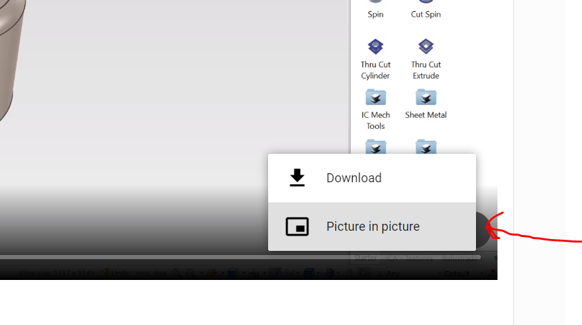
Click the button on the bottom right of the video (three dots) and press download. I'm using Chrome.
-
Constraints - How to Copy or Mirror with Parts
Josh replied to Malcolm Crowe's topic in General Discussion
That is strange. If you assemble them and do a copy/mirror of the assembly it works... but strangely not always it seems. I think expected behavior here or parts should be for the constraints to be duplicated if the user has selected more than one part that have a constraint connecting them. But it would obviously have to exclude constraints to parts that are not being copied (otherwise your copy would get stuck and not move because it could be constrained to other things around it). I imagine this complexity might be why it was chosen to not include any by default, but I think the expected behavior mentioned above would be more user friendly. Workaround for meantime, if you assemble it and create a linked assembly, it will work as expected most of the time, linked assemblies store positioning of parts too. 2020-10-31 10-34-15.mp4 -
這是顯示如何執行此操作的視頻: (Google Translate) Here is a video showing how to do it: 2020-10-31 10-15-08.mp4
-
Why does it takes a long time to upload big STP File example 168MB
Josh replied to WAENGENEND's topic in General Discussion
Hey @Cary OConnor that's super interesting to know. Can we get a list of what formats are (and are not) multi-core supported? I'll add it to the import tutorial info on the academy. -
If you just want to quickly save a bunch of holes and be able to drop them out again, you can do it this way. These can be simple straight cut holes or they can be more detailed custom holes with thread, countersink etc. Unfortunately you can't drop a pattern into the catalog because when doing so it excludes the shapes below it. But this would be a great enhancement if we could just directly save patterns to the catalog. Step a) Create a hole the size you want, use the TriBall right click drag to Link (not pattern) them to the amount you want. Step b) Hold Shift and select all the holes, then drag into the catalog. A new item will be created and when dropped out will place all the linked holes in one go. Note, the placement on drop is determined by the Anchor on the first hole you select when you begin selecting them all before dragging into the catalog. In this video I discuss the Anchor: https://www.ironcad.academy/tutorial/anchors#tools Advantages: You can do this with just about anything, any type of hole and also any feature I can think of. The Link relation is kept for the holes you dropped, however does not apply to previous holes. Each hole can be unlinked and customised if needed. Disadvantages: There is no way that I'm aware of to build in pattern-like functionality into this. So if you want to increase the hole count, you will need to copy a few more (only takes 10 seconds with the TriBall but still notable when doing 1000 times). On the same thought-train, you therefore can't build in selectable design variations or customisable parameters into the pattern. So you can't quickly switch between hole numbers and distances, or shapes etc. Note: If you are looking for pattern-like customisable functionality, it should be possible with a sketch-pattern on a cut extrude, and then some parametric design variations. So for example you could drop your pattern, then choose how many holes, how big they are, etc. Doing this is a bit more complex, and I'm going to assume the above is what you want not this, but if you need this let me know.
-
Shaded Rendering Drawing View Option Inaccessible?
Josh replied to DraftingNMS's topic in General Discussion
Yep definitely agree any bugs in precise mode should be fixed, we wouldn't expect something to be imprecise after selecting precise mode The general 3 mode system is very confusing for new and old users alike. Realistically everyone just wants an accurate drawing, no matter how the system gets there. All the work to achieve this should be done behind the scenes and not rely on the user to read a manual and understand the technicalities of 3 different view modes. Like changing the kernel, changing to a different view mode should be a very rare last-resort advanced workaround, not expected every time you want to produce an accurate export output. I see no reason there can't just be two modes, default, and complex assembly. By default it would use precise curves but still support shading, we are in a vector space and other systems support shading so I don't know why we don't. Then if the system started to slow down it would notify the user that the view had been changed to facet display "Complex Mode" to increase performance. If they go to export, it would always use precise representation. (Why would anyone ever want an imprecise export file? It shouldn't even be possible for the user to do that, it's like having a "Please stuff up this job" button for users to press accidently.) -
Shaded Rendering Drawing View Option Inaccessible?
Josh replied to DraftingNMS's topic in General Discussion
This problem/confusion is so common, surely we should have a dialog when clicking Shaded Rendering if you are in Precise mode on the view. It would just say "to shade this, we need to switch the view from Precise Mode to Draft mode" [OK] [Cancel] Furthermore I think we really shouldn't have the 3 different modes, they are unintuitive to everyone. Much easier just to have a default/normal mode which is Precise (and allows shading), then automatically switch to a "Large View" mode when the system detects the view is using too much computing power. No one wants inaccurate facet curves on their export... ever. There is never a desire for that, so it shouldn't even be possible. I've seen multiple companies stuff up DXF outputs because they exported Facets instead of smooth curves. And that stuff up is really the fault of how confusing the view modes are. -
Hi David, Here's a video for you: 2020-10-13_10-58-37.mp4
-
To do that move the curve exactly 300mm when offsetting with the TriBall. Or for more customizability, just use one curve and do a sweep with a rectangular profile at the front, that will allow you to easily adjust the sweep profile to any dimension, and also control the size with a parameter if desired. To align the profile, do a sketch "Normal to Face at Point", with the point being the end of the curve, and the face being the front of the step.
-
Thanks everyone! Great to hear!
-
UV-map workaround, export to keyshot
Josh replied to C_'s topic in Realistic Rendering and Animation
No worries, regarding KeyShot, this option is available in 2019 as well. Just go to the Add-ins Ribbon menu, then you should see KeyShot there. Click the "KeyShot Options" button. If you don't see the KeyShot add-on in there, you may need to reinstall it from IronCAD or make sure it is opened into the add-ins menu. -
Hi all! Most community members probably haven't heard from me before, but you may have heard my voice in a video or 20 I built the IronCAD Academy and also recorded many of the videos on it (but definitely not all of them!). The newest update has been the Command Videos section which you can see here: https://www.ironcad.academy/commands I wanted to mention that if you have any suggestions/feedback on how to improve the Academy let me know! Hopefully you've benefited from the academy at some stage. Josh
-
UV-map workaround, export to keyshot
Josh replied to C_'s topic in Realistic Rendering and Animation
Maybe you already know this, but as you mentioned you are new to IC this might help. You can use SmartPaint at the Face and Shape level as well as the Part level. So if you just select down to the shape or face, you can paint it a separate color. Helpful here is using the selection filter down the bottom right, which (along with the Shift Key) can help to quickly select many faces. Another tip, use the EyeDropper tool. When using this, if you select down to the Face level **before selecting the tool** then it will paste onto faces instead of onto parts, so you can quickly copy paste colors/styles around to many faces. Then before going to KeyShot, make sure "Link Parts with Same Material" is checked, and KeyShot will recognize everything that is the same color, as the same material. Doing it this way should allow you to accomplish what you want without needing to export or workaround the KeyShot integration. The added benefit here is if you change your model, you can then just click "Update KeyShot" and your new geometry will be copied across while keeping all your texture work in KeyShot. Let me know if I misinterpreted what you want to do. 2020-10-08 18-31-24.mp4 -
You could use the Sketched Bend command to draw the shape in its unfolded state, then fold it up (with the holes already cut), this might give the result you're looking for. To speed things up you could just use Convert To Sheet Metal on your existing part. I've attached a video for you. 2020-09-30 09-46-41.mp4
-
introductional material learning ironcad introductional material
Josh replied to StefanL38's topic in Services/Educational
Hey Stefan! In case you are not aware, there is also the IronCAD Academy here: www.ironcad.academy There are currently over 500 tutorials on there, in a few different languages, including some in German. There's also the YouTube channel of IronCAD4D (German IronCAD Partner) here: https://www.youtube.com/channel/UCColE0lwNCOgDC_wtpM-qsg If you have suggestions on improvements to the IronCAD Academy let me know! -
When working in the Sheet Metal tools anything that has a bend in two directions at once (broadly speaking) will be hard to do, and likely not work when unfolding. This is because it's not a "Developable Surface" which means the material would have to compress or stretch to make the shape. Try folding a piece of paper down the middle, then try bending it up in the other direction, it can't be done without ripping the paper (unless you have some very flexible paper I don't know about). That's kind of a definition of what's developable and what's not. You can make this type of shape with the press tool (video here) but you won't get much unfold information. In the real world of course these types of shapes are possible because you can stretch the metal, but it's quite hard (I imagine), to correctly predict the unfold dimensions when material is stretched and compressed in different ways. Hopefully at somepoint in the future, we will have the option to unfold things which are not developable surfaces and the system will give a "best guess" at the unfold shape. Or even just disregard the stretching/compressing if it is within a certain tolerance (i.e. if your material stretches 0.1mm on a 1000mm part, it may not bother you and you would rather get an unfold than nothing).

