
SSIMMONS
-
Posts
597 -
Joined
-
Last visited
Content Type
Profiles
Forums
Blogs
Downloads
Articles
Gallery
Everything posted by SSIMMONS
-
Good Day Will, I can give you some advice, but i'm not sure how much you will already know. 1) Wavefront files (.OBJ) are very easy to work with in certain programs (I render all my IC files in Blender through exported .OBJ format). The only time this is not easy to work with is if the normals flip and create a weird shading effect which required an additional step). As far as the workflow for wrapping the logo, my first thought was wrap emboss and use the wrapped cross section, but with a little more thought i think a curved stock would work well since you can then unfold the geometry to gain a flat image of the decal. any further advice would be pure speculation, but i hope this helps a little, Thanks. -Spencer
-

My post about Revison Table -- Post removed?
SSIMMONS replied to WPONG's topic in General Discussion
Will, Kevin said the table had limitations like Malcolm said and thought it made more sense, since it isn't really a bug, to more it to E.R. -Spencer -
Yes, Recreate display should clean up any unwanted lines and surfaces that are left behind on any geometry. -Spencer
-
@Cary OConnor Should be able to help you out with that i would think (sorry if this is incorrect Cary). They are fairly good at responding typically so it shouldn't take long for them to see this. Hope it all works out. -Spencer
-
Good Morning, I am not sure exactly what application you need this for. Is it for visual reference or mechanism operational accuracy? If its for the first, export to blender and set up key frames and rigid body modifiers in the physics tab. If for accuracy you may consider using Sim Wise (this costs money without the add on for IC I believe) using object contact and key-framing (though they key frames in sim wise make no sense to me to this day and not for lack of trying. By this i mean they always reset 360 degree rotations back to 0 even though the progression graphing is correct initially, etc.). Hope this helps, Thanks. -Spencer
-
Good Afternoon, From what i can tell it seems to always come in at the orientation in which the part was first created (+z initial). If the part is rotated or moved it still does this from what i can tell. Front View Definition has seemingly no effect on this unfortunately. Edit: It keeps orientation based on most recent save. If you hit F7 and look at the part (in the desired orientation) and hit save and then export you should be in good shape. Hope this helps. -Spencer
-
Manually hide selected lines in Ironcad drawing?
SSIMMONS replied to WPONG's topic in General Discussion
WPONG, I have struggled with clarity in 3D sketches for a long time and used many methods to solve or mediate the issue. The above mentioned is one of the main ways to clean up some excess lines, etc. You may already know this, but if not it will be a very helpful tool for you also. If you right click on a view within an .icd file you can also hide entire parts and this can quickly make a view clearer (a note can just be added saying motors hidden for clarity, etc.). Right click on view -> Hidden Parts List -> Hide Part. Hope this help you also, Thanks -Spencer -
How do I change the thickness of this?
SSIMMONS replied to LeapsofFaith's topic in General Discussion
Welcome to the community. Do you mean that you want the wall thickness thinner? You may be able to simply shell it and you can used define which faces you want to be what thicknesses or you can uniform shell the entire object. The .stl file you posted is not native to IC as far as i can tell, but it is a hard geometry to work with because of the way it is built. See below after converted to solid. Good Luck P.S. - As Cary pointed out, your best bet is to remake the part in IC because this will save you time in the long run and probably a lot of it, Thanks.
-
Your Top 10 list of most useful tools in IronCAD
SSIMMONS replied to tlehnhaeuser's topic in General Discussion
1) Triball 2) Triball 3) Triball 4) Triball 5) Triball 6) Triball 7) Triball 8) Triball 9) Triball and last, but not least..... 10) Triball Haha, but in all seriousness. When it comes to unique features that make the navigation and modeling time in a scene the triball has seriously impressed me. I know many other programs use (or have the option for) a similar tool, but IronCAD has focused on it and optimized it. Most features work with the triball and this generally enhances most features by default. I think a direction was chose and stuck to and the payoff was huge, now if only Solidworks and other users take the time to Demo they may find the same to be true. Great question and interesting answers! - Spencer -
Keep in mind that if you are using any sort of RTX GPU the above mentioned version of Blender is the only one that will work for you if you use Cycles rendering. You should be good in either version with the card you have personally. I do many many .obj file exports from IronCAD to Blender and they work fantastic. I am using it right now in fact. Good suggestions and good luck. -Spencer
-
introductional material learning ironcad introductional material
SSIMMONS replied to StefanL38's topic in Services/Educational
Stefan, Since you mentioned a background in PC Gaming it may be worth your time to have them use IronCAD to model things and export them to blender (.obj files work well) which is used primarily for video game design, rendering, animation, etc. I found when i started modeling professionally in IronCAD i was amazed at the versatility from 3D printing, CNC use, animation for advertisement of products, FEA, and many other useful things in the realm of engineering and business in general. This could be a good way to bridge the world of video games and mechanical design ideas. Blender is a free, open source, software that is fairly easy to use with a little practice. IronCAD modeling is much faster than any i have seen so designing and modeling shouldn't be a problem with a little practice and time. Soon you will want to know what else to do with your interesting ideas and designs and short animated video clips are a good way to do that. We have even modeled particle flow through machines to animate the use and applications of them with direct IronCAD exported models. Good Luck! P.S.- Also check out the Animation tools in IronCAD "Visualization" because it works very well for animating parts coming together for assemblies and other things like that and is really quick and intuitive to use. I also would definitely get some programmable mice with maybe about 4 to 12 programmable buttons, this will help a whole lot with modeling, Thanks. -Spencer -
Smart Paint - Identifying Existing and Removing Colour
SSIMMONS replied to SKELLY's topic in Tips and Tricks
If you are looking at two colors that are similar or need to match a color property from other programs, etc. you can always just look at the RGB settings of that smart paint as shown below. As far as the going back to the original color, there are several options. We use specific materials that apply a color and the automatically enter our BOM in our drawings. This is a catalog item that we simply drag and drop, but if you are not looking to get into this depth there are simple options. You can drop a new part and use the eye dropper to match the color and properties of a default object. The other option is to pick a material from the materials catalog and use it on everything as a default. I hope this helps, P.S. - If you want to color many objects at once you can assemble them and highlight the assembly. When the color is dropped you will be asked if you want to color everything. - Spencer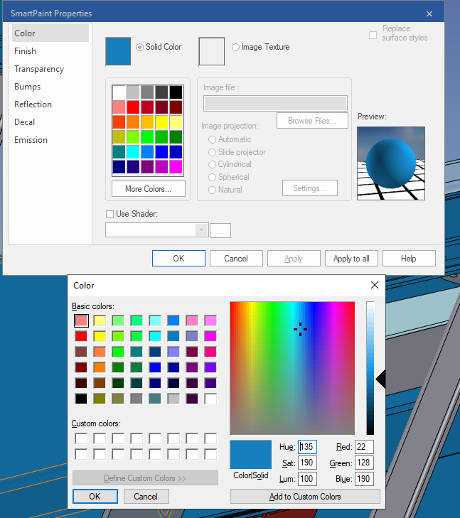
-
Off topic, but were the above images rendered in Keyshot Cary?
-
Just an additional note that might help you out because i have found it useful at times on large assemblies: There is also a "set smoothness" catalog item in the ICMech Tools that will set the smoothness of all objects in the scene with a drag and drop. This can help with giant assemblies if you need to edit something quickly you can lower the quality and then put it back when you are done.
-
YES! I wish i had seen this post many months ago because for a long time we struggled with representing wire cloth and mesh screens without bogging down the system and a google image download and a few clicks later and this is what we came up with also and it works very well. Most of the time it's hard to tell its not a real part until you zoom way in.
-
If you provide the file it will be easier to give an answer, but it seems like everything is under the same part (all of the intellishape features). So it looks like when the cylindrical block hole (that created the visuals of a hollow pipe or sleeve) is recognizing the other geometry as that same part and therefore cutting it away as you drop the sleeve on. Rebuild the piece you are dropping on and right click drag the shape into the scene and select "drop as part" if you are prompted. If not, just make sure it appears as a different entity in your design tree. The method you used should work because the part was dropped above and not on any other part, but i'm not sure how you could have only one part in this case unless a boolean or other modification feature was used after.
-
Problems with move and rotate in scene 2D sketch
SSIMMONS replied to HDEAR's topic in General Discussion
Just a heads up, if this does not work you can always check the copy box and then move or rotate copy and delete the original. I know this seems ridiculous, but it works until a fix is made. For whatever reason if a copy is made it maintains functionality. My IC is up-to-date and this issue still persists so i either try to avoid the move and rotate functions or just make copies since it doesn't come up super frequently for me, hope this helps. -
Rendering Performance Tips
SSIMMONS replied to IronKevin's topic in Realistic Rendering and Animation
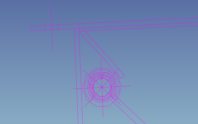
Unfortunately the source sketch was only for reference and has since been deleted because the machine was finalized that it came from. It does seem a bit extreme in comparison to the other sketches i have imported. Next time i bring one in and this happens i will be sure to save and post here, Thanks. P.S. - I was mostly wondering if there was a utility (such as the smoothing one in ICMECH) that would allow for the adjustment of resolution on sketches in 3D space. -
Hello bbuche, I am going to assume you are talking about in the IC native drawing software due to the frustration described. There are many issues with dimensioning in icd. Can you send an example of what you are trying to dimension and i will tell you how i would do it? Most of the issues don't have an actual solution, but more of a work-around. Such as placing a line with the line creation tool and then using it to dimension and setting it to a hidden-annotation layer. If you provide a little more information i may be able to help, Thanks.
-
Rendering Performance Tips
SSIMMONS replied to IronKevin's topic in Realistic Rendering and Animation
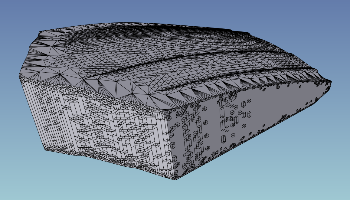
Yes, this is the correct scene. The color is just a user preference where i edited the color of 2D sketches to be more to my liking (jolizon having the same color is just a huge coincidence). I am on the most up-to-date version of ironCAD. I just made a random scene with circles in it because a curved surface is where rendering quality of 2D sketches would be most helpful. When large diameter circles are formed as reference, the snap points fall in space where the curve is actually and not where it is shown which can cause some difficulty at times. -
Rendering Performance Tips
SSIMMONS replied to IronKevin's topic in Realistic Rendering and Animation
I have attached a scene of different sized circles in a sketch for testing, Thanks. 2D Profile1.ics -
Rendering Performance Tips
SSIMMONS replied to IronKevin's topic in Realistic Rendering and Animation
Is there a way to increase the render quality of 2D sketch (reference) geometry within an IC scene? I have attached a snip of what i am referring to, Thanks.