Bryan Cargill
-
Posts
35 -
Joined
-
Last visited
Recent Profile Visitors
240 profile views

Bryan Cargill's Achievements
")
Cylinder (3/9)
0
Reputation
-
Animation - video compression
Bryan Cargill replied to scoelho's topic in Realistic Rendering and Animation
My suggestion would be to always export using full frames and then do compression as a post-process. As you are aware, the rendering of the frames can be very time consuming and, as such it is not well suited to trial and error experimentation. Rendering to full frames takes no additional time, only additional storage. Once you have the full, pure animation you are free to compress it over and over quickly as a post-process to achieve the ideal combination of quality/size. Video editing tools can do this job, but there are also tools dedicated specifically to animation compression/encoding. Check out the Microsoft Media Encoder if WMV/WMA output is acceptable (its free): Media Encoder It will take a few minutes to learn to use it-- but that is nothing compared to the time spent in re-rendering an entire animation just to tweak compression parameters. -
The problem can occur with both full gi or background illumination. They both use the background image to light the scene. With some images, this can yield blotchy, disco ball effects at low sample rates. Side note- the difference between these two gi modes is that only Full gi automatically includes indirect illumination (radiosity & caustics). All other gi modes do not include automatic indirect lighting. Full gi will include indirect lighting resulting form the environment. Turning on 'photons' will also include indirect lighting from other light sources (spotlights, area lights, etc). If you wish to see indirect lighting (Radiosity & Caustics) in all other rendering modes besides full gi, you must manually configure lights as independent, indirect light sources. With this approach you can get great caustics and radiosity effects in any render mode-- even without GI! Spot lights are great for this purpose becasue they efficiently focus the effect. See the GI page of the light properties. The blotches are becasue the light hitting a point is computed by taking several samples of the background. If you only take a few samples, you will get a noisy result if there is a high variability in the colors of the background image. More samples (higher GI Quality) will average out the noise-- at the obvious expense of longer render times. So, the simple answer is to increase the GI quality. Note that using the 'studio' backgrounds will usually not give you this issue. That is becasue they are generally simple, smooth images made with lighting in mind. You may wish to try using Colored Illumination. With it, you can choose a single constant color to represent the background light. You should choose a color that is roughly the average color of the background image. This is perfect for outdoor scenes where light seems to come from everywhere. Remember, however, that you only get the easy environmental radiosity with full gi. To get radiosity in other rendering modes you must set up lights specifically for indirect lighting. In the future, IC will support using a different image for the background image vs the background lighting. When that is possible, the solution will be simple. You will use a less detailed, blurry version of your image for the lighting. This will in effect pre-average the background. This will give you better control over the process, but will require a little more work on your part. You can do something similar today, although it requires a more manual approach. You may create and use a (very) blurry version of your desired background image when rendering. Your noise issues should be minimized. Then, when rendering mask-out the background. You may then post-process your highly detailed background back into place. The problem with this approach is that any reflections or refractions of the environment will be of the blurry image! This may or may not be a problem depending on the circumstances. Hope that helps!
-
Looking through Glass
Bryan Cargill replied to tlehnhaeuser's topic in Realistic Rendering and Animation
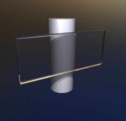
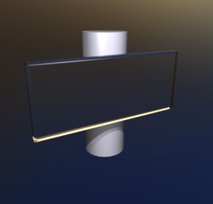
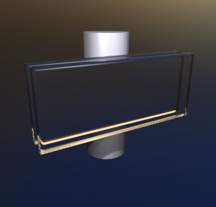
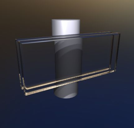
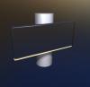
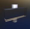
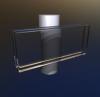
You are missing everything behind the transparent surface. This may mean it is a "ray depth" problem. The ray depth tells the renderer how many things a ray is allowed to hit before it is considered "done". Hits can be propogated from reflections or refractions. This limit is needed to speed things up and also to prevent an infinite loop in the case of two parallel mirrors (mirror A can see mirror B looking back at mirror A etc...) If the ray depth is too low-- the ray will act as if it is done (has hit the background) prematurely. This results in seeing the background where some other geometry would be expected. The default of 4 is ok for very simple scenes, but if there are multiple layers of transparency-- you must raise the value manually. For example-- looking at a cylinder through a single pane window rendered as 2 sided-- a value of 3 is ok (enter glass + exit glass + hit the cyl). Looking through a double pane window, a value of 5 is needed. Looking through a stack of 2 double pane windows-- a value of 9 is needed. etc... You don't need to understand exactly what value is required. You just need to know to raise the ray depth value if you see this issue. Try raising the ray depth value to something like 10-- it is located on the Image tab of the Advanced Rendering Properties dialog. Here is the single pane example: Ray Depth = 2 Ray Depth = 4 And, here is the double pane example: Ray Depth = 4 Ray Depth = 6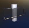
-
Yes- that is a pu1 file. Here is the water model in raw format: splash.zip
-
Hi Tom, I'm afraid you'll actually have to model the water. I've modeled this with a fluid simulator: Here is the scene: water.ics

-
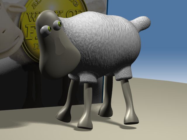
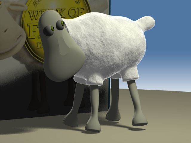
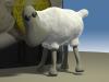
I've changed the wool material by brightening it some, using local xyz coordinate mapping (instead of uv), and mixing 2 types of noise in the bump channel. Also, I've added transparency using the metallic shader (this changes intensity at the edges of the sheep) to give his outline a slight transparency. Original: New: Here is the new file: sheep2.ics

-
No, there is no control over the details of the reflection-- your only option is to modify the image. Yes- that makes perfect sense. We could offer more options to control tone mapping of the background. I think the best answer may be to just allow users to specify different images-- then you will not be limited to only built in IC image processing. In the interim, you do have the ability to adjust the background exposure. This will change your lighting some but you should be able to roughly compensate with the GI power.
-
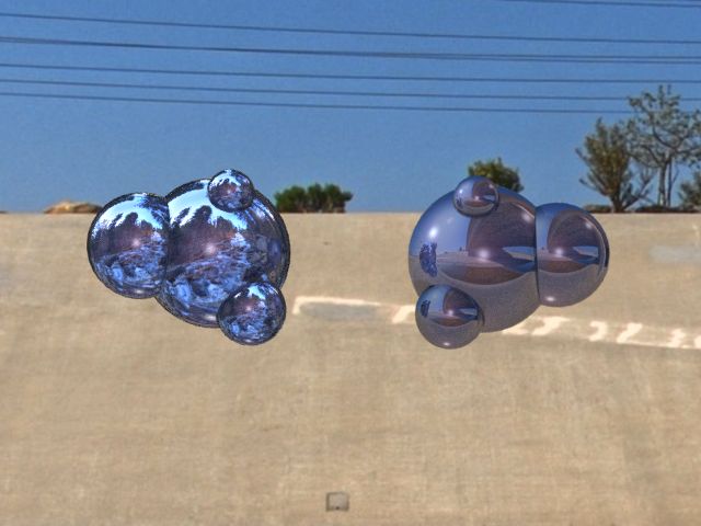
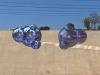
I can't speak for exactly when the enhancements to background/GI image might appear-- but it is on our radar. You may use a unique image for reflections in an existing (albeit painful) way. You may specify an image to be reflected from the "Reflection" tab of the surface finish. There is a "Reflect Image" option that allows you to browse for an image. A single global option would be much easier if everything in your scene needs to reflect something other than the background. Here is an example- the blob on the left is refelcting a winter scene while the blob on the right is refelcting a desert scene (that is also the background):
-
Yes, IronCAD's new renderer really does make full use of HDR images. It can use them as backgrounds or textures. It actually renders every image in an HDR format (you may choose to save in a typical LDR or an HDR format). First, lets start with a description of the images: Typical 24 bit low dynamic range (LDR) images are made up of Red, Green, Blue values in the range 0-255 (1 byte [8 bits] each). These are "24 bit" images becasue 8 bits Red+8 bits Blue +8 bits Green = 24 bits total. Theses RGB values can only represent a small fixed amount of intensity variation as they are limited to the range 0-255. This is in contrast to high dynamic range (HDR) images. These images are represented in different formats-- but the general idea is to use floating point values for the R,G,B intensistes. So, instead of a single byte (0-255), an HDR image might use a 4 byte (0-4,294,967,295) floating point number. This allows for much higher precision and higher range of intensisties. What does this actually mean to a user? It means a good HDR image can precisely specify very smooth gradients and subtlties. It means that areas of the image can be 'brighter than white.' You may adjust the exposure of HDR backgrounds inside IC. As the exposure is lowered the image gets darker-- but unlike LDR images, you will notice an HDR image does not get darker uniformly. Very bright areas (like the sun) will remain very bright, even as the rest of the image gets darker. When it comes to global illumination (GI) HDR images take on special significance. In GI, the background is used to light the scene. These very bright areas (outside the range LDR images) accurately represent very bright lights in your scene. Without HDR, GI would be very limited and dull. It is important to note that your monitor must eventually display these images. So eventaully things get mapped back to a LDR RGB format for display. And, if you save to an LDR format (BMP, JPG, etc) the image is mapped back to LDR RGB format. This process is known as tone mapping. Ironcad only supports one simple form of tonemapping based on an exposure and gamma setting. As far as setup is concerned-- I would recommend using HDR background images if you are using Global Illumination. If not, then I wouldn't worry very much about the format of the background. If you want the ability to modify exposure and gamma settings in the future, I'd save to an HDR format. IF not, then use a familiar LDR format. To control the "washout" I would recommend playing with the background exposure as well as the gamma/exposure adjustment after rendering. One enhancement that would help in this regard would be to allow different images for Global Illumination and for background renderering. You might use a low res, bright, washed out HDR image for lighting- and a highres jpg for the background appearance.
-
Unfortunately, the file was created in a development version of IC-- so you will not be able to open it. Here is a trick to make the mapping easier-- start out using a decal. Use the decal positioning UI to put the decal where you want it. Position it correctly and jot down the settings. Then you can turn off the decal and turn on the shader. Transfer the settings you wrote down over to the shader's mapping. I know this is a silly extra step, but it is better than doing it by just changing the numbers in the dialog. Hopefully we will get a UI for the shader mapping soon. If it is important to you-- post it as an enhancement request so it is on the radar. If you still have trouble getting it set up correctly, let me know and I will recreate the example in a previous, released version of IC.
-
Yes- you can use the transparency to get a cotton ball effect. First, create an image to be used as the transparency mask. Something like this: alpha.bmp Next, use the transparency mask in the transparency of a material. From the transparency tab of the Smart Paint dialog, choose to use an image shader. Select your image to be used. The trickiest part is getting the texture mapping correct. Youll probably want to use slide-project mapping for this. This implies the effect will only look correct when viewed from a certain angle. Once the mapping is correct, you should get an image something like this: Note that the bumps on the cotton ball are made using perlin noise- not the transparency mask. Alternately, you may try to use a non-image based shader in the transparency channel-- although it will take much trial and error to find suitable settings. Good luck!

-
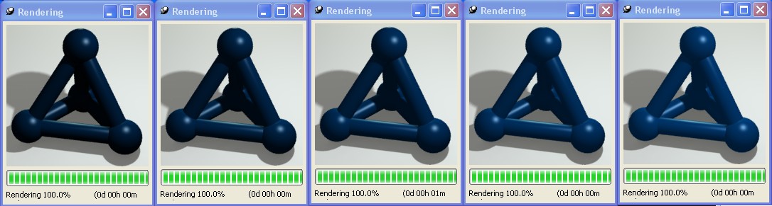
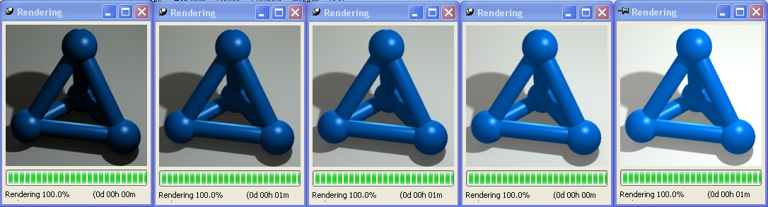
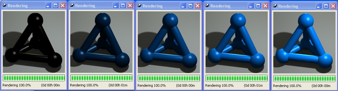
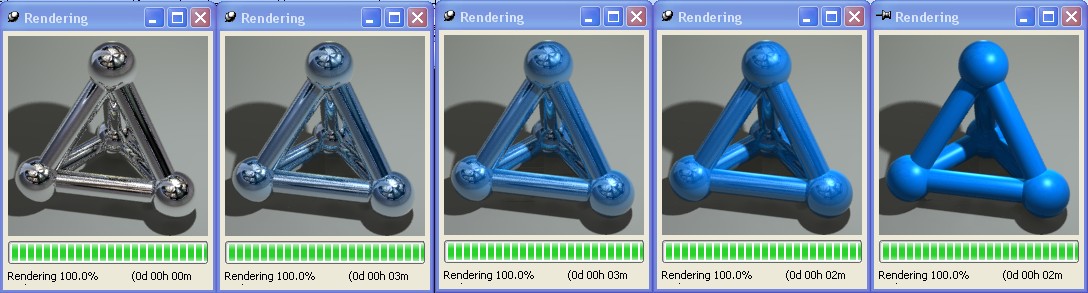
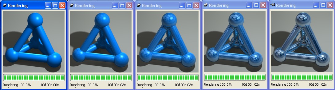
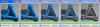
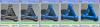
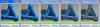
Cary asked me to give some details on the relationships between ambient intensity, diffuse intensity, reflection intensity, and fresnel amount. The ambient intensity of a material scales how much the material responds to the ambient light of the scene (under Scene Properties/Rendering/Ambient Light Level). An intensity of zero means the ambient light doesn't effect the material at all. An intensity of 100 means the ambient light effects the material at full intensity. The actual effect on the material is proportional to the power of the scene's ambient light. If the ambient light power is zero-- the materials ambient intensity is meaningless. Here, the ambient intensity of the material is varied from 0 to 100. An ambient light power of 100 is sued to demonstrate the effect. As the ambient light is made brighter, the scene will become washed out-- contrast will diminish. This is becasue the ambient light is coming from all directions simultaneously and evenly. Ambient light can be thought of as an extremely crude approximation of global illumination. Here, the power of the scene's ambient light is varied from 0 to 100. The material has an ambient intensity of 100. The diffuse intensity is very similar to the ambient intensity-- except that it describes how much the material responds to non-ambient light sources (point, spot, directional, etc). A value of zero means the material will behave as if there is no light at all. A value of 100 means the lights will effect the material fully. It really is scaling the lights brightness, for just that material. Here, the diffuse intensity is varied from 0 to 100. Reflections are a bit more complicated. The final appearance of a reflective material is the result of a combination of the diffuse+specular mixed with what is reflected. Lets call the ratio at which these are mixed the effective reflectivity. A value of 0 means no reflection (only diffuse+specular), a value of 100 means total reflection (no diffuse or specular). Note they are mixed-- not added together. So what determines the effective reflectivity? It is not necessarily the material's reflection intensity setting. It is based on a combination of reflection intensity, fresnel amount, index of refraction, and angle of incidence (angle between how we look at the surface and its surface normal). The fresnel amount controls the behavior of the reflection. A value of zero means the reflection is totally perfect and constant over the surface. A value of one means the reflection is totally fresnel based. Fresnel based reflection calcualtion increases in intensity as the index of refraction goes up and as the angle of incidence goes up. This means that surfaces viewed at glancing angles become more reflective. This is the way many materials work in real life. Using fresnel based reflections, the outer edges of a sphere will appear more reflective than the center. Consider looking through a glass window-- if you look directly in the window you will see little reflection-- but if you walk close to the window and turn your head to look at it from the side (a glancing angle) you will see almost nothing but reflection. Here is an example of the simple case, fresnel = 0, perfect constant reflection. In this case- the effective reflectivity does indeed equal the materials reflection intensity. Here the reflection intensity is vaired from 0 to 100. In this example, we vary the fresnel amount from 0 to 1. This shows the effect of blending between perfect and fresnel based reflections. The index of refraction is 1.5 which gives a weak fresnel based reflection. Reflection intensity is 100. Fresnel based reflections do not have to be weak. Increasing the index of refraction will increase the amount of light reflected. Here the reflection intensity is 100, and the fresnel amount is 1. The IOR is varied from 1 to 20.


-
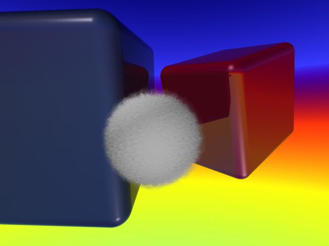
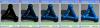
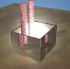
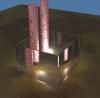
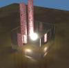
This image shows some of the limitations of glow, and what I mean about it being 2d. Notice that the glow does not appear in the refacted portion of the cylinders as viewewd through the transparent box. The glow is totally blocked by the transparent box. The glow does not appear in any reflection either. Finally, note the 'washing out' of the glow is very apparent becasue its intensity and size are both large. This image shows a smaller, glow combined with a bright point light using linear attenuation. The other lights have been dimmed to accentuate the glow. Of course the transparent box still blocks the glow, but it looking a bit better. Finally, here I've moved the glow closer to the camera by creating a second light. I turned off the glow for the original light in the box. I've made the second light (closer to the camera, in front of the box) have ONLY glow as to not effect the scene lighting.
-
Glow refers to the interaction of light with: 1. surrounding objects and 2. the atmosphere. 1. You can accurately represent the light being emitted with surrounding objects by using the emission setting under the smart paint properties. It controls the light emitting from a surface. When non-zero, area lights will be located in an approximation of the surface. The greater the emission value the greater the intensity of the light being emitted. The greater the samples value the closer the approximation of the surface. Note that this is a computationally expensive thing to do- and will slow down your renderings. Frequently, a simple point/spot/area light source is a sufficent approximation. 2. The realistic renderer does not accurately compute light-atmosphere interactions, so there is no accurate way to rendering a glowing object. However, the lights do have a 'glow' setting. It is a simple effect where a fake glow is drawn by adding the glow color to the rendered color. The effect drops off exponentially at distance. As the glow is added to the rendered color, it will wash things out-- especially if the glow is bright or white. You can think of the glow as basically a 2d effect with the exception that the glow will be blocked by objects in front of it-- without consideration of transparency. This means the glow will be blocked by your transparent surfaces. To make it visible, you will have to move the glowing light source in front of the surface. Note that the light and its glow are somewhat independent-- you may for example turn the light intensity to zero but still have a glow. This lets you locate the glow without effecting your overall lighting.
-
Sorry, I didn't even suspect there was emission in that scene. Emission will simulate light emitting directly from the surface. It does so by effectively placing many tiny area lights across the surface-- facing outwards. Depending on the settings, this can be a real bottleneck.