


Malcolm Crowe
-
Posts
1,760 -
Joined
-
Last visited
Content Type
Profiles
Forums
Blogs
Downloads
Articles
Gallery
Everything posted by Malcolm Crowe
-
 Hi Kim, This bug has also been previously reported. Ticket 113683. Malcolm
 -
Hi Harley, The tool is there in the "Modify" panel of the "Common" Tab, but the order of the panels in your Ribbon is different compared to the Default. I've just noticed the same in mine (don't know when or how that happened). Attached is the "Default" User Interface file and my updated "Custom" User Interface file (in which the Ribbon is the same as the Default). You can load either of these files (Tools/Interface Operations/Load) to alter your Ribbon, otherwise you can right-click on an empty section of the Ribbon and select "Customize the Ribbon" to manually make changes (corrections). Malcolm CAXA 2023 - User Interface - Default.uic CAXA 2023 - User Interface - Custom - 20230220.uic
-
Sheetmetal loft not working on large transition
Malcolm Crowe replied to HDEAR's topic in General Discussion
Hi Harley, The problem was resolved by rotating the circular sketch 180 deg, so that it's X-Axis is in the same direction as the other sketch. See the attached video. Malcolm Sheet Metal Loft Not Working - 20230214.mp4 -
Structured Parts - Key Differences (Document and Videos)
Malcolm Crowe replied to Malcolm Crowe's topic in General Discussion
11 - Using Datum Planes for Trimming Structured Parts - Key Differences - 11 - Using Datum Planes for Trimming.mp4 -
Structured Parts - Key Differences (Document and Videos)
Malcolm Crowe replied to Malcolm Crowe's topic in General Discussion
10 - Setting Different Colors to Bodies Structured Parts - Key Differences - 10 - Setting Different Colours to Bodies.mp4 -
Structured Parts - Key Differences (Document and Videos)
Malcolm Crowe replied to Malcolm Crowe's topic in General Discussion
09 - Splitting Body using 3D Curve and Surface Body Structured Parts - Key Differences - 09 - Splitting Body using 3D Curve and Surface Body.mp4 -
Structured Parts - Key Differences (Document and Videos)
Malcolm Crowe replied to Malcolm Crowe's topic in General Discussion
08 - Adding Datum Axis for Circular Pattern of Feature Structured Parts - Key Differences - 08 - Adding Datum Axis for Circular Pattern of Feature.mp4 -
Structured Parts - Key Differences (Document and Videos)
Malcolm Crowe replied to Malcolm Crowe's topic in General Discussion
07 - Creating and Positioning Another Body Structured Parts - Key Differences - 07 - Creating and Positioning Another Body.mp4 -
Structured Parts - Key Differences (Document and Videos)
Malcolm Crowe replied to Malcolm Crowe's topic in General Discussion
06 - Mirroring Bodies using Datum Planes Structured Parts - Key Differences - 06 - Mirroring Bodies using Datum Planes.mp4 -
Structured Parts - Key Differences (Document and Videos)
Malcolm Crowe replied to Malcolm Crowe's topic in General Discussion
05 - Datum Plane for Draft Neutral Plane Structured Parts - Key Differences - 05 - Datum Plane for Draft Neutral Plane.mp4 -
Structured Parts - Key Differences (Document and Videos)
Malcolm Crowe replied to Malcolm Crowe's topic in General Discussion
04 - Edit Sketch Cross-Section (Profile) Structured Parts - Key Differences - 04 - Edit Sketch Cross-Section (Profile).mp4 -
Structured Parts - Key Differences (Document and Videos)
Malcolm Crowe replied to Malcolm Crowe's topic in General Discussion
03 - Edit Sketch Position (Positioning Shapes) Structured Parts - Key Differences - 03 - Edit Sketch Position (Positioning Shapes).mp4 -
Structured Parts - Key Differences (Document and Videos)
Malcolm Crowe replied to Malcolm Crowe's topic in General Discussion
02 - Bodies and Features Structured Parts - Key Differences - 02 - Bodies and Features.mp4 -
Structured Parts - Key Differences (Document and Videos)
Malcolm Crowe replied to Malcolm Crowe's topic in General Discussion
01 - Coordinate System Structured Parts - Key Differences - 01 - Coordinate System.mp4 -
The intent of the attached document “Structured Parts – Key Differences” is to provide a basic understanding of "Structured Part Modelling". Within the videos of the following posts, I’ve tried to convey the basic concepts in a clear way (such as Sketch Positioning, Features and Bodies), while also trying to provide a little “taste” of how Datums, 3D Curves and Surfaces can be included for construction purposes. I've also tried to demonstrate how to use the Feature Structure (Rollback State) to create the desired associations, as well as demonstrating how to work with multiple Bodies. 01 - Coordinate System 02 - Bodies and Features 03 - Edit Sketch Position (Positioning Shapes) 04 - Edit Sketch Cross-Section (Profile) 05 - Datum Plane for Draft Neutral Plane 06 - Mirroring Bodies using Datum Planes 07 - Creating and Positioning Another Body 08 - Adding Datum Axis for Circular Pattern of Feature 09 - Splitting Body using 3D Curve and Surface Body 10 - Setting Different Colors to Bodies 11 - Using Datum Planes for Trimming “Structured Part Modelling” is really important for creating complex Multi-Bodied models (which can't be created as "Innovative Parts"). Having said that, the multi-bodied part in the following demonstration videos is not a complex model. This is simply to demonstrate some basic concepts. There is a separate forum post regarding real world "Structured Parts - Examples". Malcolm IRONCAD - Structured Parts - Key Differences (Document).ics IRONCAD - Structured Parts - Key Differences - 20230210.pdf IRONCAD - Structured Parts - Key Differences (Videos).ics
-
Hi Emil, Gustav and aalbe are correct. There is some additional video (with audio) regarding creating Symbols on the following post also. Malcolm
-
After my post above, I thought that I should test what I had suggested (to ensure that it worked). Attached is a demonstration video, which includes a couple of view related bugs(?) that I discovered, and how to work around them. Malcolm CAXA - BOM Test - Configurations.mp4
-
It is possible to combine different BOM source files into a single BOM in CAXA. In your case you could have one source file representing one Configuration and another source file representing another Configuration, with each file externally linked to the master file (referencing a specific configuration). Then import each of these source files into the 3D BOM (select Default configuration - not All Parts). For the Item Numbers to work correctly with the BOM, the Views generated within the sheet will also need to be from the specific source files. One or more Views from one source file and one or more Views from the other source file. This principle is the same as "Combining Assembly and Part Levels" within a single BOM. See the link below with more detail. Malcolm
-
Creating Hydraulic/Electrical Schematics w. CAXA
Malcolm Crowe replied to GNÄSLUND's topic in General Discussion
Hi Gustav, We don't currently produce Schematic Drawings in CAXA, but it has been on our "To Do List" for quite a while, as CAXA is well suited for this purpose. In answer to your questions: 1. Schematic drawings are drawn at a scale of 1:1 to fit within the chosen paper size. I've never come across a "Best Practice" as to whether they should be done in Model Space or Layout Space; but don't use a combination of both with View Ports in Layout Space (draw objects directly in Layout Space). If done in Layout Space you can have a separate tab (layout) for each sheet within a single file. If done in Model Space then you either need a separate file for each sheet, or you draw all sheets (with their own Drawing Frames and Title Blocks) within Model Space. Some clients are very specific about this, with some demanding a single sheet in Model Space (with a separate file for each sheet), whereas other clients don't care whether Model or Layout Space is used. 2. Yes, it is possible to list all components within a BOM. Each equipment symbol needs to be a "2D Block" with Attributes or Extended Attributes that are matched to the Attributes in your BOM style. For our "2D Blocks" our Attribute Names are the same as our Property Names from the 3D Scene, so that our BOMs work with both 3D and 2D models. If you're not familiar with this, attached is our inhouse document regarding the "Set Matching Rule" within Options. I've also attached a document regarding "Blocks - Attributes and Extended Attributes". Note that the BOM is specific to the sheet that it is on. So, quantities will be based on the Items selected in that sheet only. If you want a BOM that lists all of the Items and Quantities across multiple sheets, then I suggest creating these multiple sheets (with Frames and Title Blocks) within Model Space, with a separate sheet (also in the same Model Space) specifically for the BOM. Note that for any "2D Block" to appear in the BOM, it needs to be selected using the 2D Item Number tool. I suggest that you create a specific "Style" for this purpose, such as a Style that displays a "Tag" (Asset Number) rather than an Item Number. In the case of P&IDs, these "Tags" (Asset Numbers) typically need to be added at some point. I have logged an Enhancement Request for CAXA regarding Item Numbers, that users be able to "Toggle" on and off the Leader Line with this in mind, as "Tags" don't typically have leaders. 3. Regarding connections I would create a "2D Block" that can be dropped onto the drawing the same way as any other symbol that you will be dropping. This "2D Block" can consist of a "Circle" with added "Fill" (solid). I recommend creating a similar "2D Block" for "Not Connected" as well, that can simply snap to intersecting lines, without the need to do any trimming or drawing. The "2D Block" can mask the lines beneath it. Malcolm IRONCAD DRAFT - Blocks - Attibutes and Extended Attributes - 20221123.pdf IRONCAD DRAFT - Options - System - Set Matching Rule - 20221118.pdf -
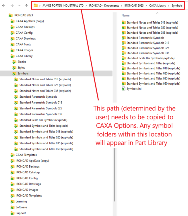
Hi Emil, It is a very simple process and is something that we do whenever setting up a new user. Create a parent "Symbols" folder somewhere on your PC, then direct CAXA to look at that folder regarding user defined Symbols. Part Library will then automatically display anything inside that parent "Symbols" folder. When you create Symbols, save them within this folder. If you have existing Symbols in another location on your PC, or on a completely different PC then simply copy them to this location. See the attached images and video. I hope that helps. Malcolm CAXA - Part Library - Path to Symbol Folders.mp4

-
Placing a feature at the origin of the coordinate system..
Malcolm Crowe replied to tgjang's topic in Tips and Tricks
This is a good tip! Note that for the first part within an empty scene it isn't necessary to hold down the "Ctrl" key. IRONCAD will automatically position the first part at the origin. Malcolm -
This updated request is that both "Material" and "Mass Density" properties be added as variables within Design Variations. Material designations change with dimensional changes, so this will help accommodate those changes. Also, the mass density of material changes (such as Carbon Steel vs Stainless Steel) can also be accommodated. Malcolm
- 1 reply
-
- 2
-

-
Adjust gap between center line and annotation
Malcolm Crowe replied to LEE MENG CHE's topic in General Discussion
Hi Lee, For your interest, below is a link to a post in 2019 where I requested control for the size of this Text Background Mask. Malcolm -
Hi Kim, These "Definition Points (defpoints)" also exist in CAXA. They are called "Derivation Points" within CAXA and are turned off by default within the Dimension Styles. If you want these to be visible on all dimensions, then change the option within the Dimension Style(s). However, if you only want these to appear sometimes, then for the selected dimension you can simply turn on within the Properties Browser. See the attached images and video. Malcolm CAXA - Definition (Derivation) Point Options.mp4
PointOptions.thumb.png.58259549da93454b45a88fa4020df212.png)
PointOptions.png.c0c2d2d04dbce8d00313145dee02fa07.png)
-
The "Print Tool" in CAXA DRAFT allows printing of multiple files and multiple sheets (layouts). Malcolm


PointOptions.png.46565d8fa6a4d070e9aac58e5d8a002e.png)