Malcolm Crowe
-
Posts
1,760 -
Joined
-
Last visited
Content Type
Profiles
Forums
Blogs
Downloads
Articles
Gallery
Everything posted by Malcolm Crowe
-

CAXA - turning of Information fields on cross-hair cursor
Malcolm Crowe replied to HDEAR's topic in General Discussion
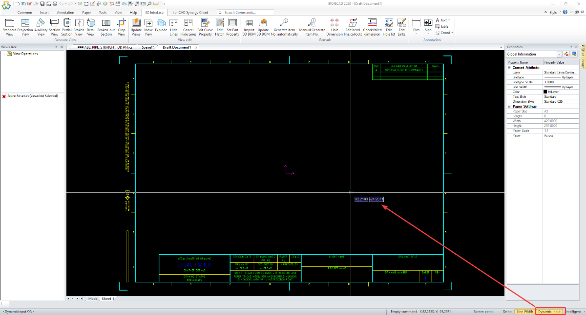
Hi Harley, Disable "Dynamic Input" on the Status Bar (bottom right). See the attached image. Malcolm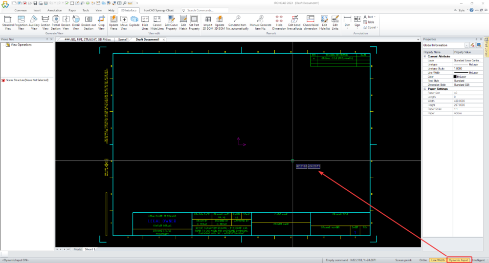
-
Structured frame - How can I edit density of blcok?
Malcolm Crowe replied to Bertrand Kim's topic in General Discussion
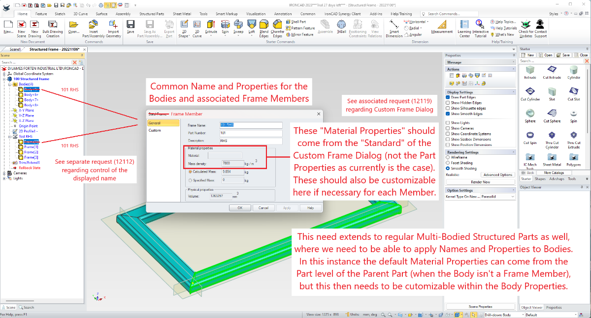
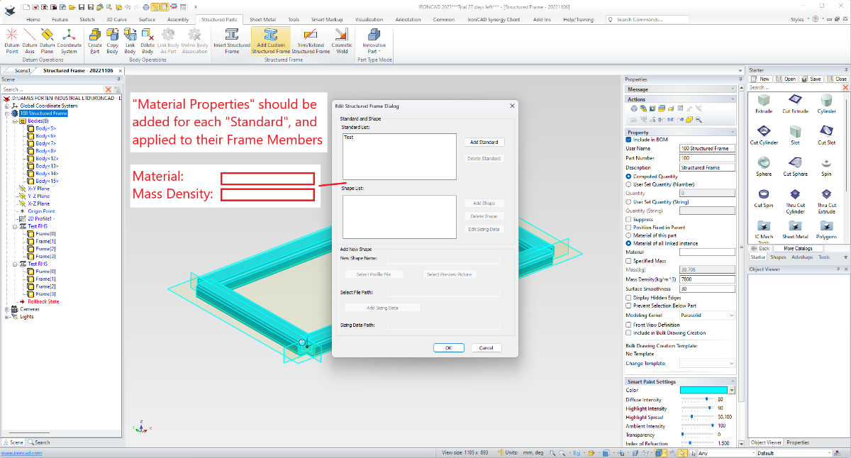
Hi Kim, The attached video demonstrates what Kevin is referring to regarding "Hidden Bodies" and the need to "Delete" them (at the end of the Feature Structure). Currently all "Bodies" (Frame Members) within a Structured Part adopt the Material Properties of the Parent Part. This isn't ideal, as it limits how this tool can be used. I have previously requested (tickets 12118, 12119, 12120, 12672) that Users have the ability to customize the Material Properties of "Bodies" (Frame Members) within Structured Parts. Hopefully these requests (and other associated enhancements) will be implemented sooner rather than later. Malcolm Structured Frames - Part Density is Applied to all Bodies.mp4

-
Hi James, The link below is to a previous Enhancement Request in 2020 (ticket 114048) regarding dragging-and-dropping Text Properties from a Catalog onto selected Bodies (Frame Members) within a Structured Part. In a separate Enhancement Request in 2022 (ticket 11891), I've also asked that Default Property Templates for Structured Frame Members be added within Options, so that Frame Members can be automatically populated with the desired Custom Properties during creation. Malcolm
-
While there isn't the ability to create Tables in CAXA from Design Variations in the 3D Scene, it is possible to create Tables based on external Excel Spreadsheets. There is currently an Enhancement Request in place for the ability to import and export data to and from Design Variations via Excel Spreadsheets, in a similar way to what is done with Structured Frames. I personally want to be able to use common Data Sources for our Structured Frames and Design Variations. If this request is implemented, then CAXA will be able to create Tables from Design Variations indirectly using exported Excel Spreadsheets. The attached video demonstrates creating a Table in CAXA using one of our Structured Frame Size Data spreadsheets. Malcolm CAXA - Creating Table from External Spreadsheet.mp4
-
Structured Model Frame to CAXA Draft Part Drawing?
Malcolm Crowe replied to tgjang's topic in General Discussion
Regarding question 2. Attached is a video demonstrating how to provide "Control" over the position of the Vertical Frame Members. This method uses 2D Sketches, where the position of the Vertical Lines (Paths) can be controlled independently using Sketch Shape Handles (and unlocked dimensions). If the Sketch Dimensions are "Locked", these positions can also be controlled using Parameter expressions, so that they follow any size changes made to the top and bottom Frame Members. Also attached is a video demonstrating what Cary is suggesting, regarding adding vertical 3D Curves for these Vertical Members. This is a good solution if you always want these Vertical Members locked to the referenced geometry of the Top and Bottom Members. Malcolm STRUCTURED FRAME - Positioning Vertical Members with 3D Curves.mp4 STRUCTURED FRAME - Positioning Vertical Members with 2D Sketches.mp4 -
Changing shapes into parts
Malcolm Crowe replied to wile e coyote Genius's topic in General Discussion
This situation is easy to do, and it's also easy to fix. One solution is to make multiple copies of the current Part (that contains the multiple Shapes) in the same location, and to then delete the unwanted shapes from each Part, Then, reposition the Anchor of each Part. See the attached video. Malcolm IRONCAD - Creating Multiple Parts from Multiple Shapes.mp4 -
Hi Kim, It's a good thing that the forum provides the ability to translate what you've written. When a new drawing is created in CAXA, the "Current Layer" of that new drawing is based on the "Current Layer" of the Template from which the drawing was created. So, you need to set the desired "Current Layer" in your Templates. This is demonstrated in the attached video. Malcolm CAXA - Template - Current Layer determines Current Layer in Drawing.mp4
-
This is possible in CAXA DRAFT (including multiline text). In the process BOM items lines are created, but the visibility of these can afterwards be toggled off. No need to move off the sheet. Malcolm
-
For those interested, I've attached documents that show the "Custom Settings" that we use within IRONCAD and CAXA DRAFT (specific to 2023 PU1). These "Custom Settings" have a red border around them to identify them as being different from the "Default" setting. The reason for sharing these, is that the "Default" settings aren't going to be optimal for every user. As a result, many users won't be as productive as they could be. Our "Custom" settings aren't going to suite everyone either, but they might be helpful as a comparative guide. Malcolm IRONCAD DRAFT - Options - Custom Settings - 20230905.pdf IRONCAD - Options - Custom Settings - 20231012.pdf
-
CAXA - Paratables (Annotative Blocks)
Malcolm Crowe replied to Malcolm Crowe's topic in Tips and Tricks
Hi Kim, The "Properties" displayed in the Properties Browser of my Paratable are the "Attributes" that I defined inside my Paratable. If the "Fill in Paratable" dialog is empty (as in your image), this is because there aren't any "Attributes" defined inside the Paratable. In the attached video I create a Paratable using "Text" and a Paratable using "Attributes" to demonstrate the difference. I hope that helps. Malcolm CAXA - Paratables - Attributes vs Text.mp4 -
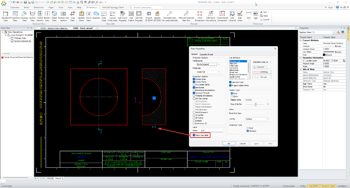
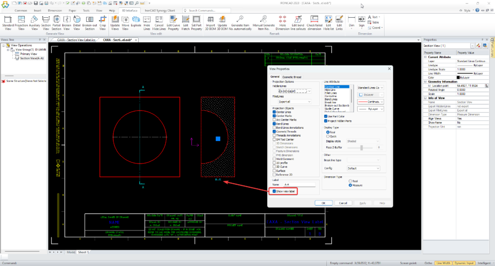
Adding to what was previously mentioned above, attached is a video demonstrating the influence of the "Current Text Style" on automatically generated Section View Labels, along with how to create a specific Text Style to achieve the desired text height in these Section View Labels (taking into account the View Scale and Paper Scale). Malcolm CAXA - Section View Label - Text Style.mp4
-
For users needing "Annotative Blocks" that scale with the "Paper Scale", there are 3 types of “Annotative Blocks” in CAXA DRAFT. 1. Drawing Frames 2. Title Blocks 3. Paratables The name “Paratable” is a bit unfortunate, as this tool doesn’t need to be limited to Tables. It can in fact be used for creating any type of “Annotative Block” (consisting of attributes, line elements, text, etc), that needs to scale with the “Paper Scale”. Attached is our in-house document regarding "Paratables", along with a demonstration video. Malcolm CAXA - Paratables (Annotatibe Blocks).mp4 IRONCAD DRAFT - Paratables (Annotative Blocks) - 20230522.pdf
-
Hi Harley, You've done another good job with these demonstration videos. Thanks for sharing. Malcolm
-
CAXA places its automatically generated View Labels inside the Generated View (which is a type of "Block"). Regarding DWG Editors (like CAXA), any annotations that are placed inside "Standard Blocks" do not scale with the Paper Scale. This is why you're not seeing the View Label change like other annotations do when the Paper Scale changes. Only annotations placed inside special "Annotative Blocks" scale with Paper Scale, and the only "Annotative Blocks" within CAXA are the "Drawing Frames", "Title Blocks", and "Paratables". For CAXA to create the View Label at the correct text height, the "Current Text Style" at the time of generating the View needs to be set to the desired height. One way to do this is to have a "Scaled Text Style" that you can simply toggle on (set as current) when required. Alternatively, you need to double-click on the Generated View to enter into "Block Editing Mode", so that you can then edit the text height of the View Label manually (while inside the Block). Another option is simply to disable the View Label within the View Properties, and to drag-and-drop your own custom View Label into the drawing (which is what we do). Malcolm CAXA - Section View Label - Paper Scale.mp4
-
Left or right when making sheet metal bend reliefs? Revised videos
Malcolm Crowe replied to HDEAR's topic in Tips and Tricks
Hi Harley, Thanks for sharing. You've done a good job with these videos, and I've now added them to my collection. Malcolm -
CAXA - How can I disassociate Dimensions from the object?
Malcolm Crowe replied to Bertrand Kim's topic in General Discussion
Hi Kim, Thanks for sharing your reasons. I find it really annoying when dimensions lose their association and need to be replaced, so I can understand why you would want to place them without associations in the first place. Even though I don't copy and paste dimensions between views myself, this second reason also makes sense. Thanks again. Malcolm -
CAXA - How can I disassociate Dimensions from the object?
Malcolm Crowe replied to Bertrand Kim's topic in General Discussion
Hi Kim, I found your request to be very strange, because I don't know why you would want to disassociate dimensions from their geometry. However, there is a workaround when it comes to linear dimensions, where you can drag the end of one of the Extension Lines away from the geometry and place it back again. This breaks the association. There is also a document specific setting within Options that you may not be aware of also. These are demonstrated in the attached video. Malcolm CAXA - Disassociate Dimensions.mp4 -
If you need a free STEP Viewer for checking the 3D Models exported from IRONCAD, then the OPEN DESIGN ALLIANCE (ODA) recently released their free "Open STEP Viewer". This works in a very similar way to their "Open IFC Viewer" (for viewing BIM models). Attached is a video that I created for a client demonstrating some of the functionality within this STEP Viewer. Open STEP Viewer Open IFC Viewer Malcolm OpenSTEPViewer - Basic Demonstration.mp4
-
Structured Frames - Using Sketch Patterns
Malcolm Crowe replied to Malcolm Crowe's topic in Tips and Tricks
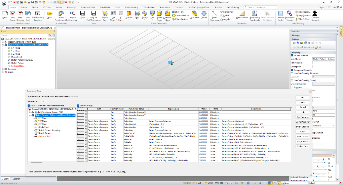
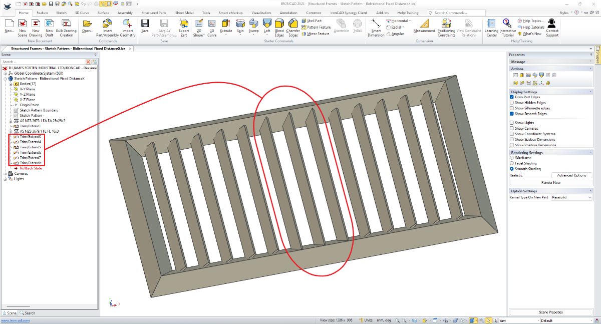
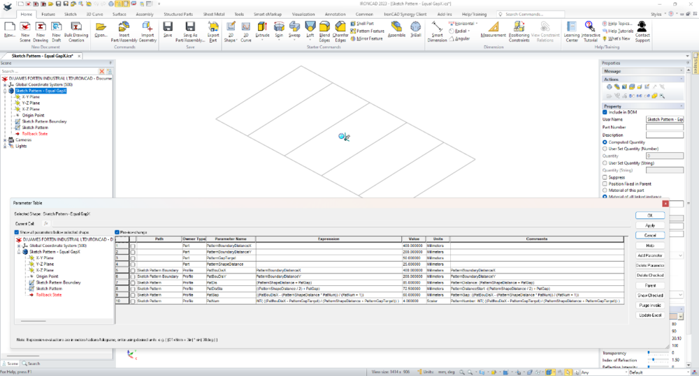
Hi Harley, The bus has already left the building, and that particular example that you're referring to uses the "Pattern Feature" tool rather than "Sketch Patterns". Attached is a video demonstrating what I understand to be what you're asking. I've also attached the ICS files and an image of the Parameters. Within the Sketch Pattern Sketch there is a Sketch Pattern towards the right and a Sketch Pattern towards the left. Then within the Parameter Table there are expressions (a little involved) that calculate the "Pattern Number" for each Sketch Pattern, based on the dimensions of the Sketch Boundary (first sketch). Malcolm Structured Frames - Sketch Pattern - Bidirectional Fixed DistanceX.mp4 Sketch Pattern - Bidirectional Fixed DistanceX.ics Structured Frames - Sketch Pattern - Bidirectional Fixed DistanceX.ics

-
Structured Frames - Using Sketch Patterns
Malcolm Crowe replied to Malcolm Crowe's topic in Tips and Tricks
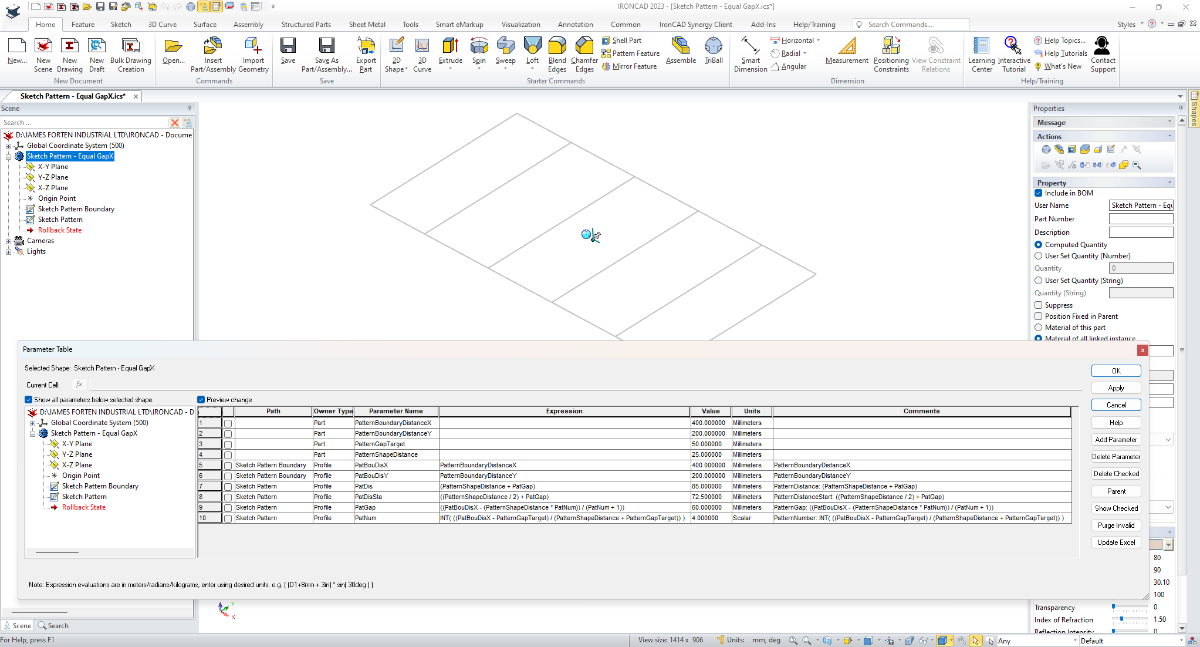
For those interested in understanding how these "Sketch Patterns" and Parameter Expressions work, I've attached the ICS files, along with images of the Parameters. Malcolm Sketch Pattern - Equal DistanceX.ics Sketch Pattern - Equal GapX.ics Structured Frames - Sketch Pattern - Equal DistanceX.ics Structured Frames - Sketch Pattern - Equal GapX.ics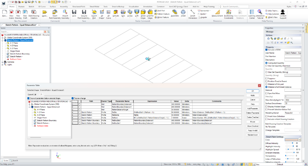
-
Many users will be familiar with creating "Patterns" using the TriBall or perhaps the "Pattern Feature" tool. But another option is using "Sketch Patterns" within 2D Sketches. This is especially useful when used with the "Structured Frame" tool. Attached are a couple of videos demonstrating what's possible. One example uses Parameter Expressions to calculate an "Equal Distance" between Patterned Objects. Whereas the other example uses Parameter Expressions to calculate an "Equal Gap" between Patterned Objects. Malcolm Structured Frames - Sketch Pattern - Equal DistanceX.mp4 Structured Frames - Sketch Pattern - Equal GapX.mp4
-
How do I insert an external part file into a part file?
Malcolm Crowe replied to tgjang's topic in General Discussion
Hi @tgjang, Which video are you referring to? The image shown above is of an externally linked "Part" (543) within an externally linked "Sub-Assembly" (513). As Kim mentioned above, these external links were created using "Save As Part/Assembly External". Do you want a "BREP Feature" within a "Part" to be externally linked to a "Body" within another "Part"? Malcolm -
CAXA's "Quick" option is very similar to the video (with similar number of clicks), with the exception that the length of the extension lines is set within the options below rather than by dragging. CAXA's "Align" option (with Dim Line Closed) is even better, as the text is all aligned (unlike in the video above), so no adjustment needed afterwards. Malcolm
-
Problems using project and extrude feature IronCAD
Malcolm Crowe replied to cadimonium's topic in General Discussion
Also, have these projected lines been set as "Construction" lines? Malcolm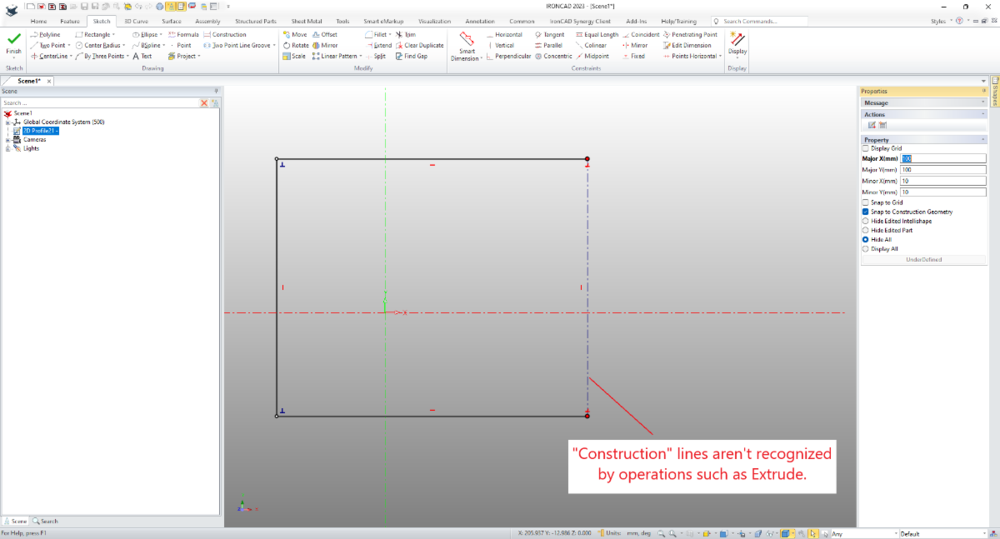
-
Problems using project and extrude feature IronCAD
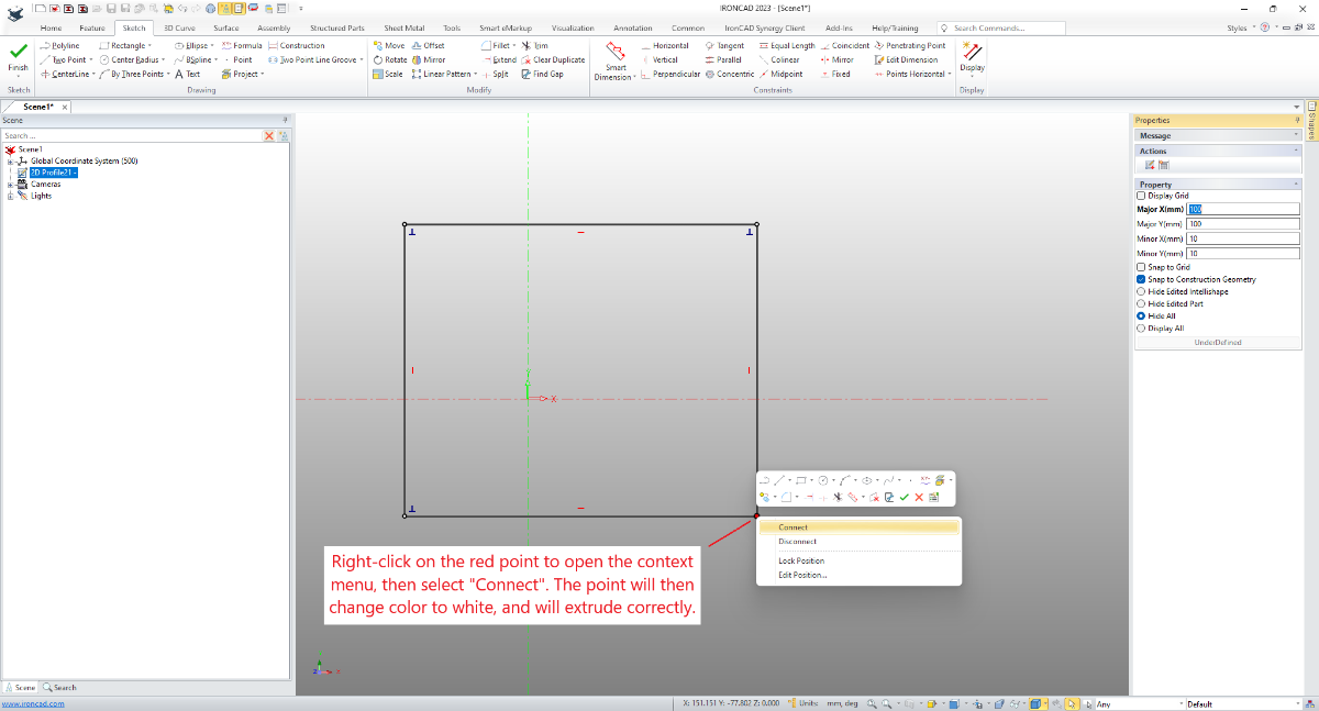
Malcolm Crowe replied to cadimonium's topic in General Discussion
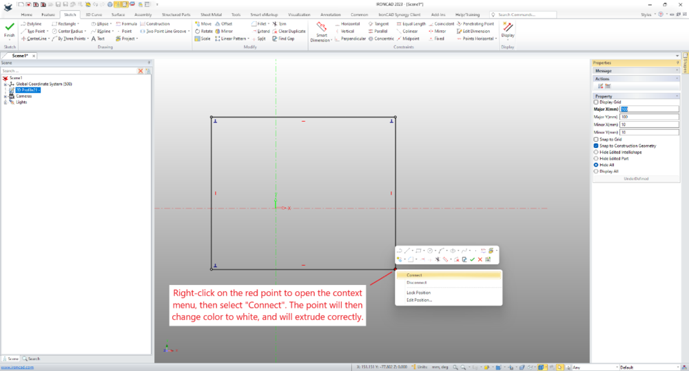
Within the sketch, check the corners where the various lines meet. They need to be "Connected", which is indicated by a white dot. If any of these aren't white, right-click on the connection and select "Connect". Malcolm