Malcolm Crowe
-
Posts
1,760 -
Joined
-
Last visited
Content Type
Profiles
Forums
Blogs
Downloads
Articles
Gallery
Everything posted by Malcolm Crowe
-
Hi. Out of interest, what 3D modelling software are you used to working with? The reason I ask is that it might help identify a method that you are familiar with. For example, I suspect that you are used to working in the equivalent of IRONCAD's "Structured" mode, as opposed to IRONCAD's "Innovative" mode. If you switch to "Structured" mode, then the various features maintain their relative associations without the need to add constraints or "Smart Dimensions". The video link that you posted also relates to a "Structured" part (note the icon of the part in the Scene Browser or History Tree). Malcolm
-
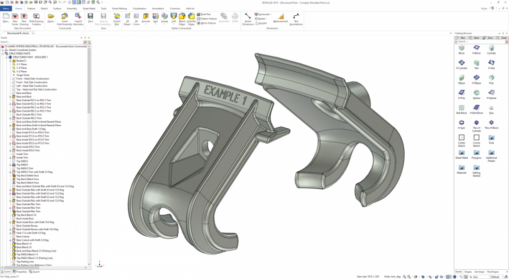
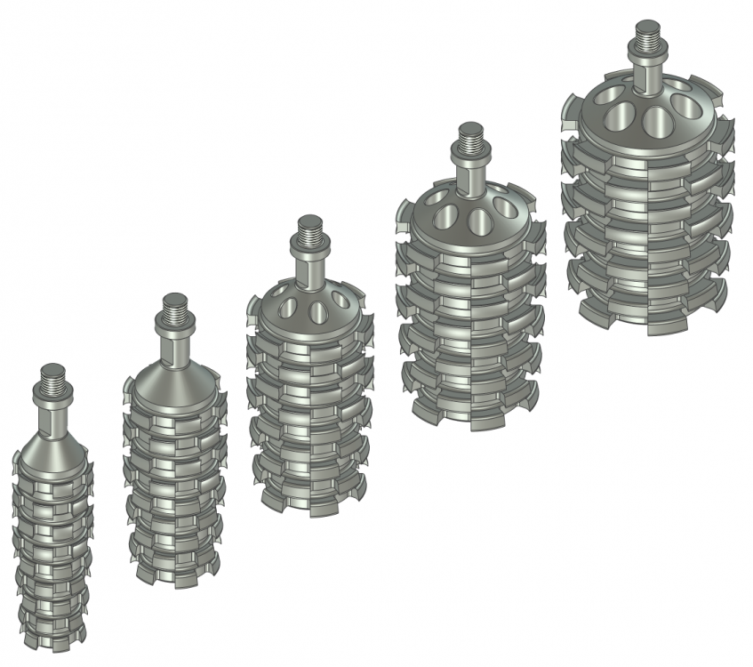
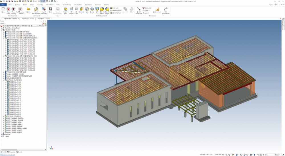
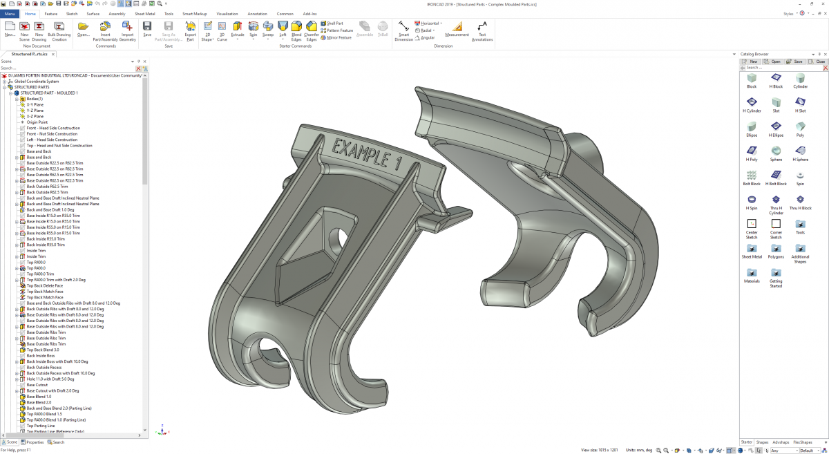
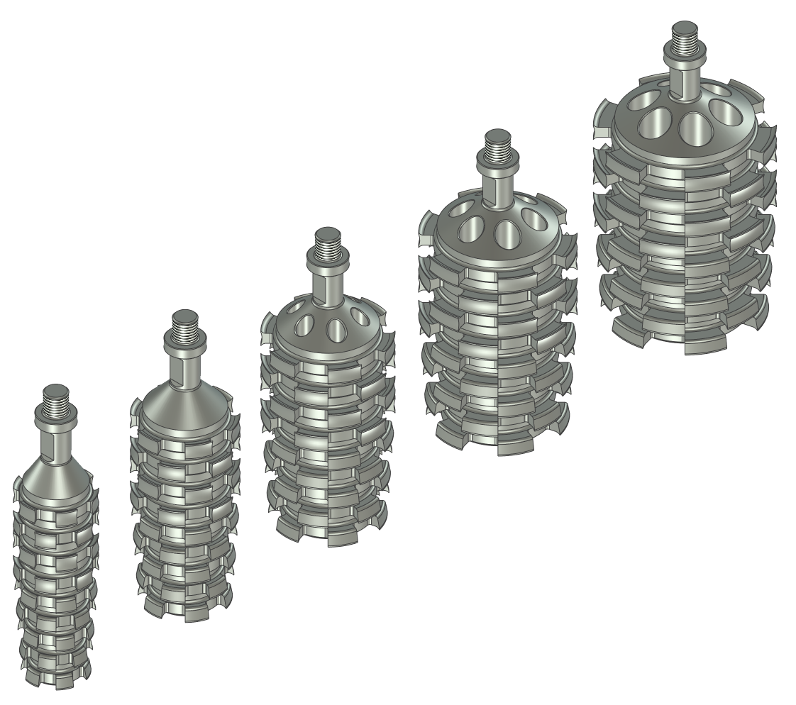
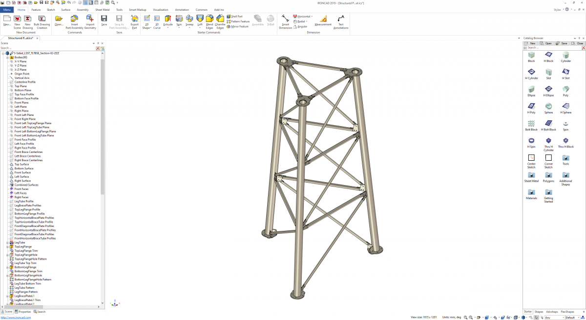
One of the key advantages of IRONCAD is that it offers users the option of working in either "Innovative" or "Structured" part modes. Personally speaking, "Innovative" is my preference for simple 3D models, as they are fast to create and edit. However, "Structured" is my preference for complex 3D models (and 2D layout sketches). These require more thought and take longer to construct; however, these can be easier and faster to edit (changing parameters) than "Innovative" parts and assemblies. Attached are some examples of "Structured" parts and assemblies. 1. Complex Moulded Parts (using multiple steps to construct the necessary features and draft angles) 2. Complex Sheet Metal Parts (using multiple construction elements within the part) 3. Parametric Part Families (family of parts based off common structured parametric part) 4. Parametric Assemblies (multiple associated "bodies" - that can be externally linked also) When you need to use construction elements (such as sketches, 3D curves, surfaces, and reference bodies), to help construct a complex part; then "Structured" mode keeps these construction elements within the part itself (and maintains the associations between those elements). Malcolm Structured Parts - Multi-Bodied Assemblies.mp4
-

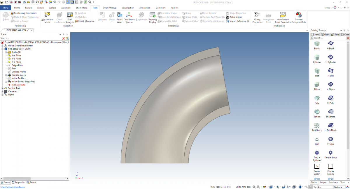
Inside draft angle 80 degree pipe
Malcolm Crowe replied to emil.rindell's topic in General Discussion
Hi Emil, The way to approach this is using the "Sweep" tool, as it has the option to apply draft through the sweep. Attached is a video, image, and model demonstrating this. I hope that helps. Malcolm PIPE BEND WITH DRAFT.mp4 PIPE BEND WITH DRAFT.ics
-
Hi David, Yes ICD does produce better renders. For your interest, if you set the background colour in CAXA to white it improves the quality of rendered views. We work with a black background, but when we want to create a PDF that includes a rendered view we set the background to white before setting the view display type to shaded with edges. Attached is an example. Also, yes it is difficult to get your head around CAXA's BOM; but once you've set up the BOM Styles how you want (along with the "Options/System/Set Matching Rules"), then it works really well. Malcolm CAXA 2019 PU1.1 - Improving Quality of Rendered Views.pdf
-
Hi David, I don't work in ICD; but for your interest (and other users) I have described how to do this with CAXA within the IRONCAD DRAFT forum. Malcolm
-
This is an interesting question. Within the CAXA forum I have posted the following solution, which might help you achieve what you want. You might be able to achieve a similar result with ICD as well (I don't use ICD so haven't tried). https://community.ironcad.com/index.php?/topic/13419-tip-linking-configuration-names-to-title-blocks/ Malcolm
-
My post about Revison Table -- Post removed?
Malcolm Crowe replied to WPONG's topic in General Discussion
Hi Will, I noticed that Kevin replied and moved it to the Enhancement Requests forum. Malcolm -
This is a simple thing, but when editing the values inside a Parameter Table, where you click makes a difference to whether the value is highlighted for editing. Don't click on the value itself, as it won't highlight the value for editing. Instead, click to the right of the value. This will highlight the value for entering the new value. The attached video demonstrates this. Malcolm Editing Parameter Table Values.mp4
-
If you have geometry in one 2D sketch that you would like in another, you could cut and paste that geometry; or you could use the drag-in-drop capabilities of the catalogs. In the attached video I copy three different 2D sketches into a temporary catalog, then drag-in-drop them into another sketch that was previously empty. A typical application could be inserting regularly used logos and text into sketches for engraving or embossing. Malcolm Combining Multiple 2D Sketches into One.mp4
-
Trimming and joining surfaces... still learning
Malcolm Crowe replied to WPONG's topic in General Discussion
Hi Will, In this particular example you might find the "Extrude as Surface" technique to be easier. In the attached video (and modified version of your file) I have created a structured part (but works for Innovative also). 1. Create a sketch to represent the contour of the surface. I projected directly from you surface model, but you could project directly from anything (solid, 3D curve, etc). 2. Using the sketch use the "Extrude" tool, and select "Generate as Surface". It doesn't answer your various questions about trimming and merging surfaces, but is a good fit for this particular example. Malcolm Extrude as Surface Technique.mp4 Part937 - Extrude as Surface.ics
-
Creating Sheet Metal Parts from Thickened Surfaces
Malcolm Crowe replied to Malcolm Crowe's topic in Tips and Tricks
For those interested, the attached video is another example of sheet metal parts created by first creating trimmed surfaces (within a structured part), followed by using the Thickening Tool. Malcolm IRONCAD 2019 PU1.1 - Sheet Metal Parts from Trimmed Thickened Surfaces.mp4 -
Within "Structured Parts" it is possible to fully define (or constrain) the "position" of all sketches. IRONCAD provides various options for defining these sketch positions relative to planes and drawing elements within the structured part itself. In this simple example, there are 3 sketches. All three are positioned on the same plane within the structured part. However, the third sketch (Moving Body) has the "X Direction" defined as well. This "X Direction" is associated to a construction line within the first sketch (Linkage and Cylinder). The construction line within the first sketch (Linkage and Cylinder) is driven by an angle variable. As this variable is changed, the position of this line within the first sketch changes. As this line changes, the third sketch (Moving Body) moves with it (since the "X Direction" of the sketch is associated with the line). This is a very simple example of how you can use sketches within "Structured Parts" for mechanisms. Malcolm Rotating Sketches (Mechanisms) within Structured Parts.ics Rotating Sketches (Mechanisms) within Structured Parts.mp4
withinStructuredParts.thumb.PNG.0f479d953b4a8ea5a85ef9162ffb9cfc.PNG)
-
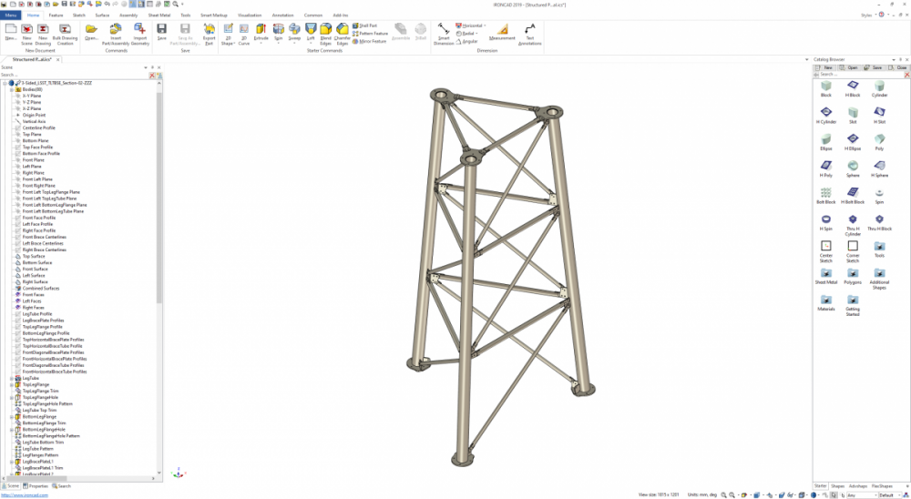
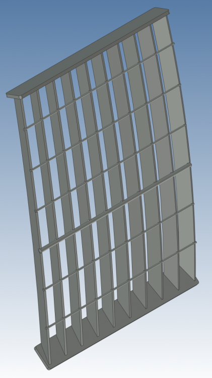
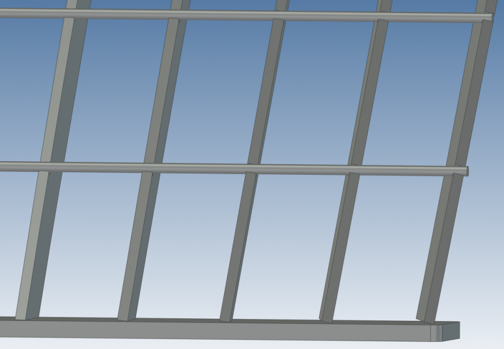
This is another example of creating sheet metal parts using thickened trimmed surfaces. Again it involves using a "Structured Part" to contain the 2D sketches and surfaces used to create the thickened parts. The difference here is that we are using the "Extrude" tool (outside cut) to trim the surfaces to the desired profile, before using the "Thickening" tool. In this particular example (a ROPS Grille), the Vertical Blades need to have an even spacing (100mm) at the top and bottom, and angled towards a common point (operator), and welded to inclined Lower and Upper Plates. The geometry of the fabricated part dictates that only the outside edges of the Vertical Blades make contact with the Lower and Upper Plates. As a result, the surfaces constructed in the "Structured Part" are the outside faces of these Vertical Blades. From these construction surfaces the "Thickening" is directed inwards to create the finished parts. The attached video and model demonstrate the technique. Malcolm Creating Parts using Thickened Trimmed Surfaces 01.mp4 Creating Parts using Thickened Trimmed Surfaces.ics
- 1 reply
-
- 3
-

-
If you find that you have modeled a single part, that should really be 2 or more separate parts, then the following options for separating might help. Option 1: Copy the part into as many as you need, then delete the applicable features not needed in each part. Option 2: Within the Scene Browser, select to highlight the features wanted. Then left click and drag into a temporary catalog. From there, drag these features back into the scene as a new part. Option 3: There is also a "Split Part" tool in the "Modify" section of the "Feature" Group of the Ribbon Menu. This may be more applicable for some applications. Attached are simple videos of options 1 and 2. Malcolm IRONCAD 2019 PU1.1 - Separating Part Features into Separate Parts - Option 1.mp4 IRONCAD 2019 PU1.1 - Separating Part Features into Separate Parts - Option 2.mp4
-
Creating Sheet Metal Parts from Thickened Surfaces
Malcolm Crowe replied to Malcolm Crowe's topic in Tips and Tricks
File attached. IRONCAD 2019 PU1.1 - Sheet Metal Part from Thickened Surfaces.ics -
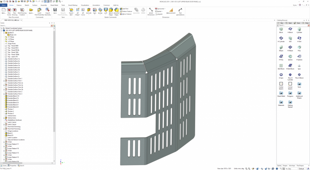
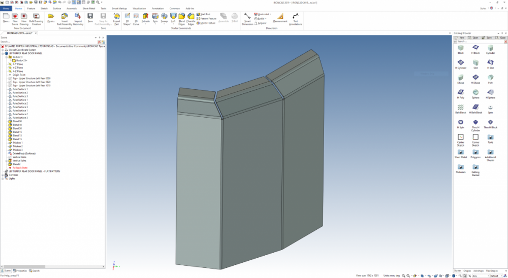
Occasionally we need to model sheet metal parts where the standard sheet metal tools aren't able to provide us with the desired end result. On these occasions we use a technique based around the following: 1. Structured Part Mode (to keep all of the construction elements associated inside the part) 2. Surface Tools (driven by 2D sketches) 3. Thickening Tool In the attached image and video, the sheet metal panel is made up of 3 vertical sections. These sections then have horizontal bends at different angles that then need to meet together (with a gap). It takes a bit of practice regarding understanding how "Structured" models work, and how best to implement the principle of this technique, but you end up with adjustable parametric models. When the model is complete, you can then create the flat pattern simply using the "Solid/Surface Flat Pattern from Faces" tool. Malcolm IRONCAD 2019 PU1.1 - Sheet Metal Part from Thickened Surfaces.mp4
-
When using the Smart Dimension on Arcs within the 2D Sketch, it is possible to toggle through the following options before placing the dimension. Arc Radius Arc Length Arc Angle After selecting the Arc, use the Right-Click of the mouse to toggle through the options, before placing the dimension with a Left-Click. Video demonstrating attached. Malcolm IRONCAD 2019 PU1.1 - Right-Click to Toggle Smart Dimension Options.mp4
- 1 reply
-
- 2
-
-

-
If you need to create linked parts with unique features, then this is possible with "Structured" parts, and using "Associate Brep with Body". If this description doesn't make sense, it means associating an external Brep part (or multiple parts - one by one) with the Body of the structured part. In the attached video I have started with a Base Part (using structured mode). From this Base Part the "Body" is saved to separate external parts (Linked Part 1 and Linked Part 2). For demonstration purposes these Linked Parts are inserted into the same scene as the original Base Part. As their starting point these Linked Parts share the same Body of the Base Part. If the Base Part changes, then these changes are reflected in the Linked Parts. However, these linked parts can also have additional unique features added to them. Malcolm IRONCAD 2019 PU1.1 - Different Linked Parts from Base Part.mp4
-
Hi Will, The attached are MP4 videos and play fine for me inside the post. I don't know the cause of your error message. Malcolm
-
Hi Will, Depending on how complex the cavity is (and whether you can suppress its features), you might want to consider the attached technique that involves using the "Trim" tool. Malcolm Offset Cavity Solid using Trim Tool.mp4 Offset Cavity Solid using Trim Tool.ics
-
Hi Will, In the attached example I have created offset surfaces from a cavity and then "Solidified" the resulting closed surfaces. I have skipped the "Extracted Surface" step that you have used and gone straight to the "Offset Surface" tool. In case you aren't aware, to select the internal surfaces I am holding down the "Ctrl" and "Alt" keyboard buttons. When I click on a surface the resulting context menu gives me the opportunity to choose the hidden face that I want to select. Does this achieve what you want? Malcolm Solid from Extracted Offset Surfaces.mp4 Solid from Extracted Offset Surfaces.ics
-
Set Scene to Parasolid Kernel before Exporting
Malcolm Crowe replied to Malcolm Crowe's topic in Tips and Tricks
When importing STEP files, set the scene to use the Parasolid kernel; and in the STEP import options check the "Source for Part Name". See the link below if part names aren't being imported as expected. The "Source" may need to be set to "Definition". Malcolm -
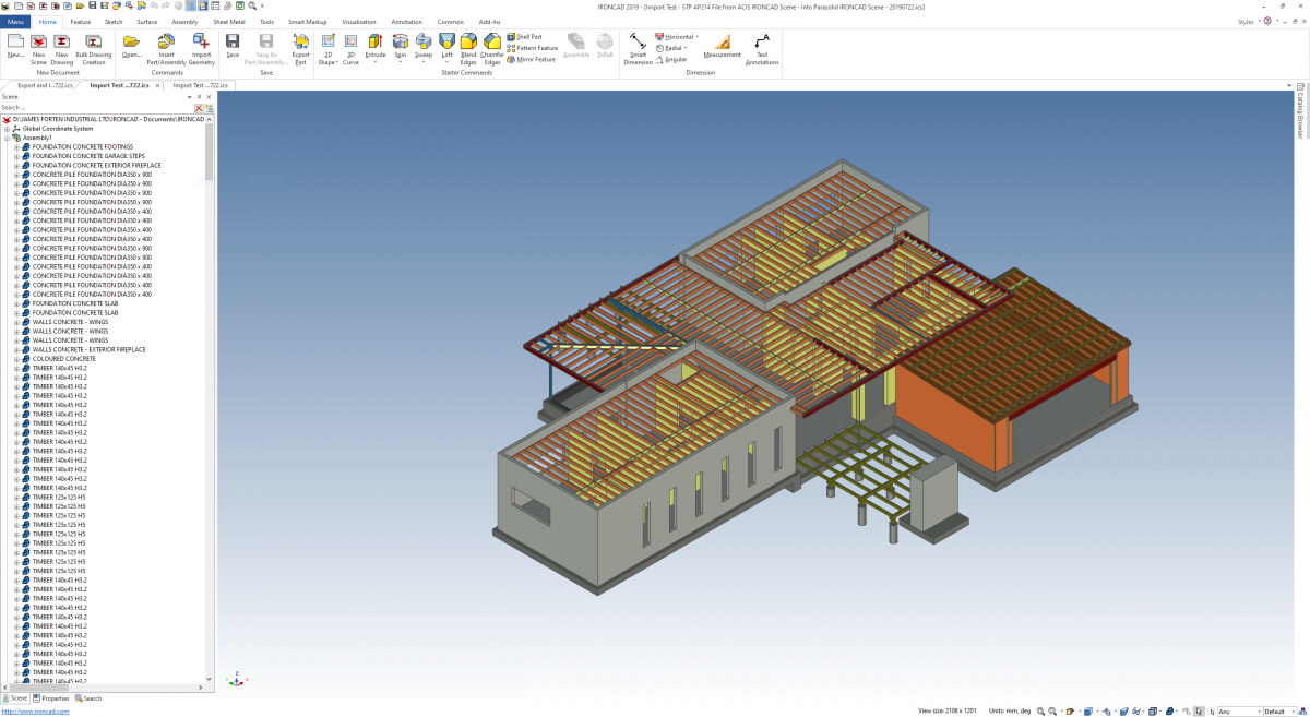
Historically we have used the Parasolid kernel by default, but recently we have been using the ACIS kernel, as we have been exchanging models with other ACIS based CAD software. We have discovered that this change in kernels within the 3D Scene has affected the structure of our exported files. The ACIS kernel doesn't convey any of the assembly structure of the original model. It will only convey parts. What we have discovered is that when we export STEP files (which are supposed to convey the assembly structure), if the kernel of the IRONCAD Scene is set to the ACIS kernel, then the assembly structure isn't conveyed in the exported STEP file. However, if the IRONCAD Scene is set to the Parasolid kernel then the assembly structure is exported as expected. Attached are images of the following Scene Browsers: 1. The original IRONCAD Scene 2. The imported STP AP214 File from ACIS Scene (parts only, no assembly structure) 3. The imported STP AP214 File from Parasolid Scene (correct assembly structure, although reordered) So the tip is, to ensure that the IRONCAD Scene is set to the Parasolid kernel before exporting, if you want the assembly structure to be exported as well. Simply selecting STEP isn't enough. Malcolm


-
Anyone else experiencing lock up with Cadenas add-on?
Malcolm Crowe replied to HDEAR's topic in General Discussion
Hi Harley, I had a similar experience to Joseph when I tried as well. Malcolm


withinStructuredParts.PNG.0428bd667e5f26fd18f4a8f29d0ece22.PNG)