


Malcolm Crowe
-
Posts
1,760 -
Joined
-
Last visited
Content Type
Profiles
Forums
Blogs
Downloads
Articles
Gallery
Everything posted by Malcolm Crowe
-
Hi David, I'm not sure what you are referring to. Is the link to the other post not working for you? If so, the applicable text of Cary from that post is below: "When you use Parasolid, the source for the structure can depend on the system it is exported from. In this particular example, when importing select the import options. Go to STEP and select Definition. This will import the structure correctly for Parasolid. ACIS will be looked at to see why it is not able to read the definition. My assumption is that ACIS does not have the top node which it then pulls incorrectly." Malcolm
-
Hi David, I personally don't understand the reasons, but based on previous experience STEP files can import differently depending on what kernel is selected in the scene before importing. In the case of Harley, I suspect that his scene was set to PARASOLID (as was mine). In the case of Joseph I suspect that he may have had the scene set to ACIS. The link below is to a post where Cary helped me out previously regarding "The Source of Part Name" when it came to using PARASOLID. Cary might be able to explain further. Malcolm
-
Hi Harley, I experienced the same problem using the default STEP import settings. For this to work you need to change the "Source for Part Name" import setting from "Default" to "Instance". See the attached image and video. Malcolm STEP Import Setting - Instance.mp4

-

Grouping Limited to Same Assembly Level
Malcolm Crowe replied to Malcolm Crowe's topic in General Discussion
Thanks Spencer and Kevin. -
We haven't used IRONCAD's "Grouping" tool in the past, but have decided to test it's capabilities and limitations on a project. Grouping seems to be limited to parts and assemblies that are at the "Same Assembly Level". In the attached video I can group assemblies and sub-assemblies that are at the same assembly level, but when selected parts and assemblies are not at the same assembly level, then the option to group is not available. Is this limitation the normal behavior for grouping in IRONCAD? Malcolm Grouping Limited to Same Assembly Level.mp4
-
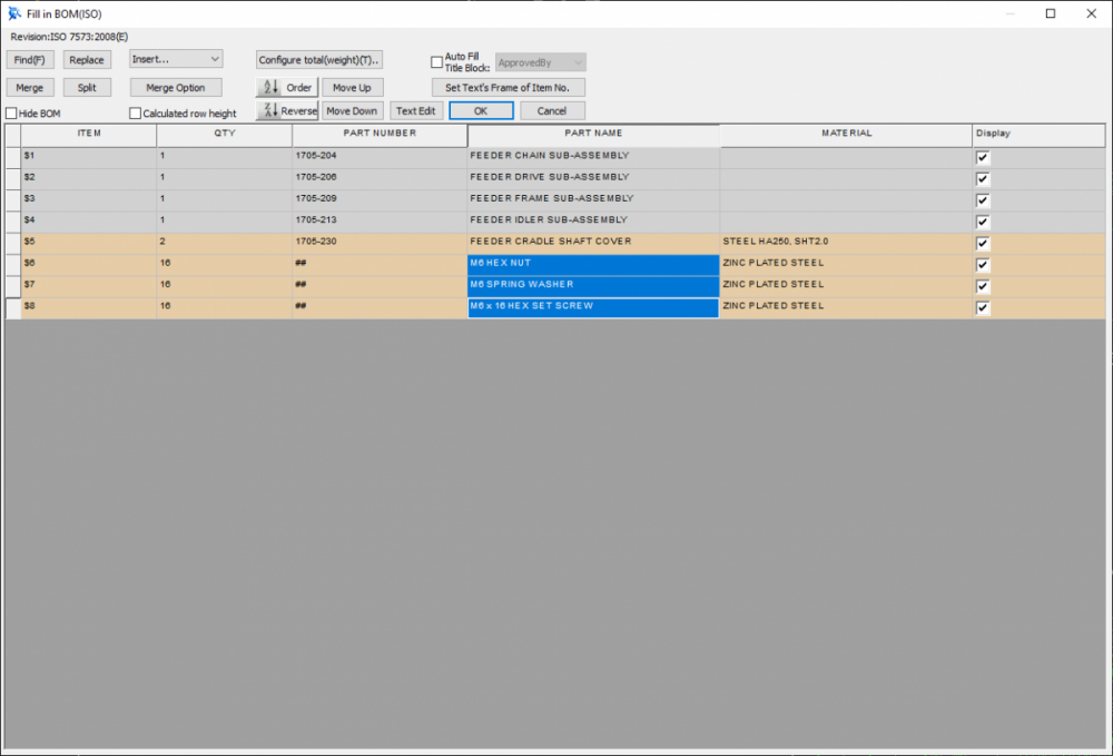
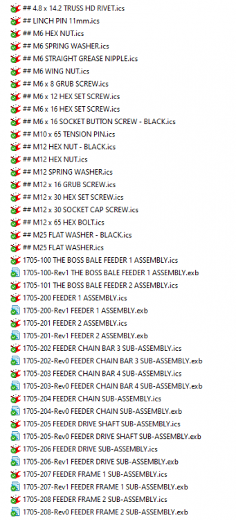
Hi Spencer, The reason for giving standard components such as fasteners "##" as a part number is simply our company practice for grouping and sorting reasons within the project folder. See attached image. This is a general Windows File Explorer thing for us, where we use "##" in front of file names that we want to group, and "#" in front of folders that we want to group. Attached are images of a typical BOM for an assembly of sub-assemblies. We sort by part number, and then have the "##" parts at the end sorted by part name. This BOM is only showing the fasteners required to assemble these sub-assemblies together. Within the 3D scene these fasteners are at the same level as the sub-assemblies. Each of these sub-assemblies then have their own drawings and BOMs (including related fasteners). When requested, we also create specific BOMs on separate sheets for complete projects (for materials ordering purposes). For example, all of the structural steel members (including lengths), or all of the fasteners. I hope that answers your questions. Malcolm

-
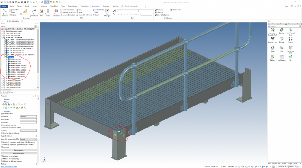
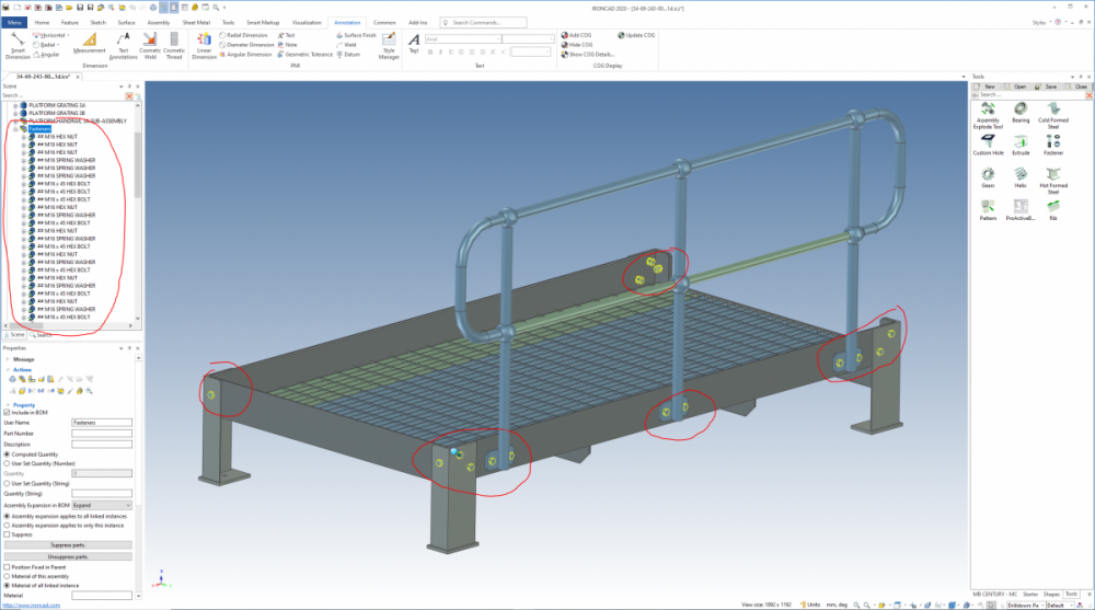
One of the things that we like to do is to sort our parts alphabetically before giving parts numbers, and to sort standard components such as fasteners also. In a large assembly this can be a tedious process when it comes to fasteners. The following is a trick that we have recently discovered that simplifies this sorting. Step 1. Place the parts within a temporary assembly (within the desired final location). Step 2. Disassemble the temporary assembly. The parts are automatically sorted during disassembly. Attached are some before and after images along with a video. Malcolm Sorting Parts Alphabetically.mp4
-
No mirrored side of sheet metal in unfolded state.
Malcolm Crowe replied to Orlik's topic in General Discussion
Attached are a couple of videos in which I have mirrored bends and other features. These are unfolding OK. Can you provide more information or attach your model? Perhaps your mirrored bends aren't attached to the base stock. I have attached a 3rd video in which I haven't perfectly positioned the TriBall before mirroring. I have moved the TriBall 0.01mm from where it should be (too small to notice in the folded model). Note the effect during unfolding. Is this what is happening? Malcolm Unfolding of Mirrored Bends 1.mp4 Unfolding of Mirrored Bends 2.mp4 Unfolding of Mirrored Bends 3 - Not Attached to Base.mp4 -
Thanks Tom, The approach lends itself well to implementing parameters and IRONCAD's Smart eBehavior, and doesn't require creating 3D curve file paths for getting from point A to B. Malcolm

-
Thanks for the reply Kevin.
-
Hi Kevin, My fasteners have always defaulted to "English" rather than "Metric" (which is what I would prefer). My Windows 10 regional settings are set to English (New Zealand). Am I missing something, such as a setting somewhere else? Malcolm Fasteners Default to English rather than Metric.mp4
.thumb.PNG.da3760902814caa9678c08fac445615a.PNG)
-
Thanks Cary. Hopefully it helps Harley.
-
And this is how you can add blends to the ribs, to create the rounded rib effect. It needs to be a "Full Round" blend, and added prior to the "Shell" feature. Malcolm Flexible Hose Along Swept Bend - Adding Blends to Ribs.mp4 FLEXIBLE HOSE with Blends.ics
-
Hi Harley, Attached is a possible approach for you to consider. I have created a "Section" of hose as a Structured Part (which is adjustable via its sketch dimensions). Having created this "Section" I have then dragged different variations of it into a temporary catalog and dragged them back into the scene to assemble the complete hose. Attached are 2 videos showing the 2 steps, along with the file (created in 2020). Note that I am holding down the "Shift" key while dragging from the catalog, so that the "Section" snaps to the center of the edge I am selecting. Malcolm Flexible Hose Along Swept Bend - Assembly of Segments.mp4 Flexible Hose Along Swept Bend - Segment Construction.mp4 FLEXIBLE HOSE.ics
-
This link may be of interest. Malcolm
-
In the video I was dragging a "Part" from one "Assembly" to another. You can't drag "Intellishapes" between "Parts". Malcolm
-
"Intellishapes" are part of the same "Part", so they will share the same properties (name, colour, etc). Your model should consist of individual "Parts" (constructed using Intellishapes) within "Assemblies". Regarding colour, I don't know how you can have different colours for different Intellishapes, but it is possible to have different colours for surfaces. Select the desired surfaces then drop the desired colour onto them. These surfaces will now have colours independent of the "Part" colour. See attached video. Malcolm Changing Colour of Surfaces.mp4
-
Just to be sure, you are referring to "Parts" and not "Intellishapes". Is that correct? I think that Kevin is referring to "Intellishapes" within a "Part". There are a couple of things that you might be doing, if I have understood what you are trying to do correctly. 1. When you copied the parts, did you "Copy" or "Link"? If linked, when one changes the other changes. 2. If you want the "Copied" or "Linked" parts to be part of another assembly, then you need to drag the parts into the desired assembly in the "Scene Browser" on the left. The attached video demonstrates both of the above. Malcolm Copy verses Link.mp4
-
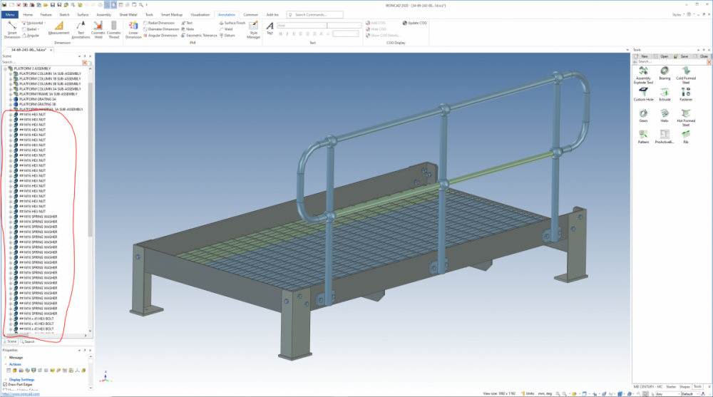
Different positions of parts in sub-assembly and main assembly.
Malcolm Crowe replied to a topic in General Discussion
Hi, Hopefully the attached image and video helps explain what is happening. If in your main assembly the "Local Configurations Override External Links" is selected, then the position of parts in the assembly can be different to that in the sub-assembly. If this is unselected (as per the image), then both the assembly and sub-assembly will be the same. Malcolm Local Configurations Override External Links.mp4 Local Configurations - Assembly.ics Local Configurations - Sub-Assembly.ics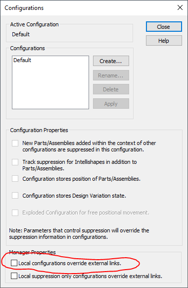
-
For your reference attached are the scene files used in the previous videos. Malcolm COMPRESSIBLE SEAL.ics COMPRESSION SPRING.ics
-
I tend to use "Configurations" with the help of "Design Variations" to display parts and assemblies in different states. "Design Variations" enable you to drive "Parameters" (including Locked Smart Dimensions) within the scene. In the attached examples I am using Parameters to drive a Dimension in a 2D sketch of a Compressible Seal, Locked Smart Dimension between parts (controlling positions), and the extrusion distance of an intellishape within a Structured Part (Compression Spring). 1. Compressible Seal 2. Compression Spring I didn't want to go into all the detail of explaining how Parameters, Design Variations, and Configurations work; but hopefully this will demonstrate what is possible. Others may have other suggestions as well. Malcolm COMPRESSIBLE SEAL.mp4 COMPRESSION SPRING.mp4

-
In the attached video I am editing the value of the Locked Smart Dimension. Select the the Intellishape that belongs to the Smart Dimension. Double-click on the dimension and the dialog box opens. Change the value and select OK. This can also be done by right-clicking on the Smart Dimension under Constraints in the Scene Browser (History Tree). Malcolm Editing Locked Smart Dimensions - Innovative Part.mp4
-
When I originally switched from SOLIDWORKS to IRONCAD I got very frustrated when I couldn't do things the way that I used to in SW. It took me a long time to realize that IC would never be as good as working like SW as SW is. So I needed to adapt and understand how IC worked. As I became familiar with IC I discovered that I could achieve almost everything that I could in SW, but it just went about it in a slightly different way. If I was to go back to SW now I would be very frustrated that it wouldn't be able to do what IC can do. Malcolm
-
Attached are a couple of videos demonstrating a couple of methods of how to maintain the position of one feature (Intellishape) relative to another. I have used the example of constraining the bottom of a blind hole within a block, where I want the position constrained relative to the base of the block. Sorry if this isn't exactly what you are trying to do. 1. Constraining Features by Sketch Position - Structured Parts 2. Constraining Features by Smart Dimensions - Innovative Parts Note that for "Smart Dimensions" to behave as constraints they need to be "Locked". This is demonstrated in the second video. When working with "Structured" parts, understanding how to position (constrain) the underlying sketch positions relative to planes and other features is critical. Malcolm Constraining Features by Sketch Position - Structured Part.mp4 Constraining Features by Smart Dimensions - Innovative Part.mp4 Constraining Features.ics
-
Attached are some videos demonstrating the following: 1. Mirroring Parts - Innovative Using TriBall 2. Mirroring Features - Innovative Using TriBall 3. Mirroring Features - Innovative Using Mirror Feature Regarding the TriBall, when you see it change colour to "White", I have pressed the "Space Bar" to enable me to position the TriBall where I want on the Part/Feature. Pressing the "Space Bar" again reattaches the TriBall to the Part/Feature, ready for moving, copying, mirroring, patterning, etc. Malcolm Mirroring Parts - Innovative Using TriBall.mp4 Mirroring Features - Innovative Using TriBall.mp4 Mirroring Features - Innovative Using Mirror Feature.mp4


.PNG.927bd2ad8213a4b71d69392a854378fa.PNG)
