


Jonas@Solidmakarna
-
Posts
2,287 -
Joined
-
Last visited
Content Type
Profiles
Forums
Blogs
Downloads
Articles
Gallery
Everything posted by Jonas@Solidmakarna
-
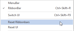
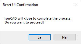
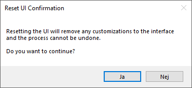
9. Reset UI and Reset Ribbonbars - two options under the right click menu of the user interface. Right click in an "empty area" under the ribbon bar (usually to the far right side). Reset UI - will close IRONCAD and remove all the UI XML files (under %appdata%\ironcad\...). The original UI setup from the default installation will be used instead and the XML files will be created in the %appdata%\ironcad\... folder again when IRONCAD is closed the next time. Reset Ribbonbars - will try to reset the UI (XML-files) while IRONCAD is still open - (probably) similar to the previous Reset UI option that was available before v2023.
-
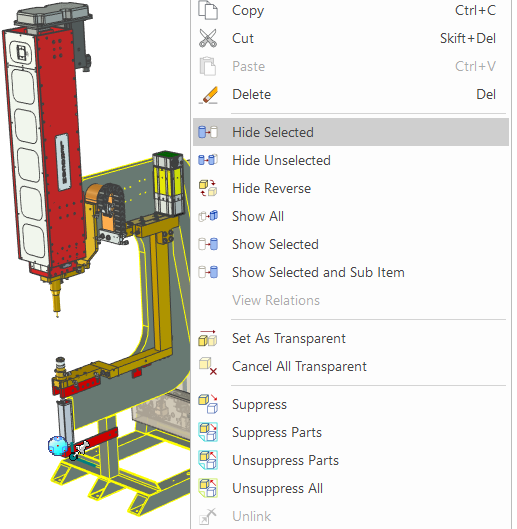
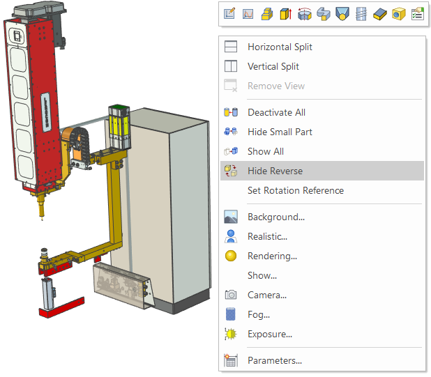
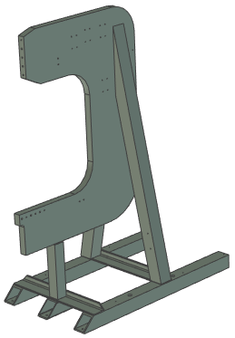
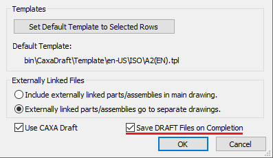
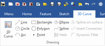
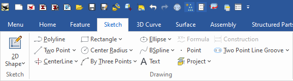
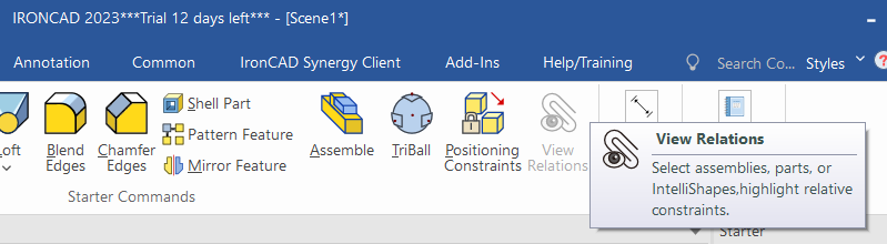
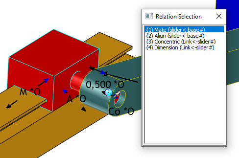
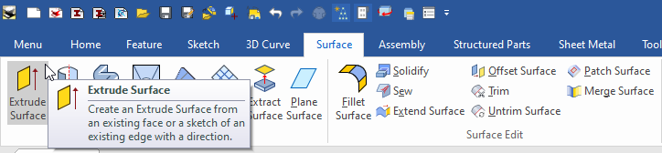
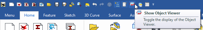
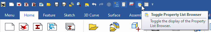
Here are some images for points 1-6; 1. Hide Reverse - Will quickly reverse the hidden and visible objects with each other. Could maybe be renamed Reverse Hidden/Visible Objects instead? Below, the frame of the Lerocon C-Frame Electric nut welding robot is first made hidden, then the visible objects are reversed into hidden, while the hidden frame is shown (alone). 2. Bulk Drawing Creation, Save DRAFT Files on Completion - will store the drawing *.EXB file, directly after the drawing has been created, in the same folder as the 3D *.ICS file. 3. Direct access to 2D Sketch and 3D Curve commands - start drawing a 3D Curve Spline or a Sketch Circle without having to "define" the origin or plane for the tool first. Video made by Kevin: 4. View Constraint Relations - will show all the constraints applied to a part/assembly listed in a window. 5. Extrude Surface - a new button under the Surface ribbon, for a function that has previously been a bit "hidden" as a toggle under the Extrude tool. With the new button it is now available directly with the other surface tools. Select a planar face or a sketch for the surface part. 6. Object Viewer and Property List toggle buttons in the Quick Access Toolbar - an easy way to toggle the visibility of the two Object Viewer and Property List Browser windows. The active setting is stored with the UI when IRONCAD is closed.

-
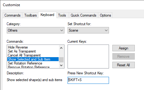
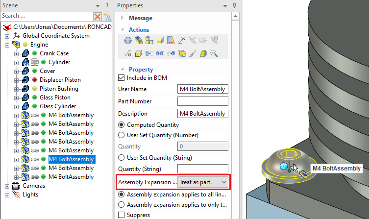
7. [Ctrl] left click directly on a sub assembly set to Treat as Part. In earlier versions you would hit a part below that assembly instead. Btw, remember the new shortcut key introduced with 2022 PU1 - Quick Select the Parent Assembly - it will still find the "last sub assembly in the structure" when you left click while holding down the [ ` ]shortcut key (acute accent - though that button is replaced with the [Ö] / [Ø] button on Swedish/Nordic keyboards). Even if the assembly placed below an assembly which is set to Treat as Part. 8. New shortcut key added for the Show Selected and Sub Item. Beside it you also see new shortcut key settings for the new tools Hide Reverse, Set Transparent and Set Rotation etc.
-
Can I change Smart Dimension color before creating?
Jonas@Solidmakarna replied to Bertrand Kim's topic in General Discussion
We made a report about that a while ago, which you can refer to: Ticket #7907 - Smart Dimension Color -
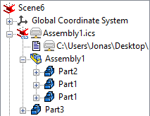
Cary, what if the "Scene File Container Assembly" would use another type of assembly icon in the Scene Browser? Maybe the red IC beam (same as the top icon) instead of the yellow assembly icon? The name of the "Scene File Container Assembly" should then be the same as the Scene File name (*.ICS). This is a quite common thing and often then an issue, specially for new users but also experienced users sometimes forget how this works. I've explained exactly what you did in the video countless of times to so many users. I don't think it would become harder to understand with the ICS file icon instead of a "regular" assembly icon. It would also make it easier to spot by support and (hopefully) also tell the users that it isn't a specific (top level) assembly from another file but "the whole content" of that ICS file.
-
Here's a post from our tech blog about 20 free fonts to use for (laser) cutting sheet metal. If you want to switch language of the page, have a look at the top left corner on the page. https://www.solidmakarna.se/supportblogg/20-gratis-typsnitt-for-laserskarning
-
Making Outside Cutted Cylinder item
Jonas@Solidmakarna replied to Bertrand Kim's topic in Tips and Tricks
As a reseller in Sweden, we have made a customized version of the Starter catalog. It should be the one you see in that webinar too. If you have IronCAD DCS 2022 with PU1 installed, you can download this catalog from here: StarterSwe.icc -
When you open a *.DWG/*.DXF/*.EXB file that has a font file which you cannot read/find - a "replacement font" will be set instead. This is message only comes up one time per *.SHX file. The next time you open a file which uses that *.SHX file you won't get any question. If the incorrect fonts have been read once, then you must remove a temporary file/folder where the "replacement font" has been set. This is being stored in the "Roaming" folder for CAXA: %appdata%\CAXA\CAXA CAD CXIC-INT-IRONCAD 2022 (x64)\22.0\Temp I think it is the file named BigFont.ini that should be removed, but I think it is fine to remove the whole folder. Most stuff there will be recreated when you run IRONCAD again.
-
Since the \Program Files folder is protected by Windows UAC (User Account Control) you must first copy the files to another folder. It isn't possible (I think) to copy from a mapped (network) drive and paste directly to a folder under \Program Files. First paste to a "temporary folder" on your Desktop. Then you can copy/move the files on your local machine. Just say Yes to the UAC question when you paste the files to the ...\Font folder.
-
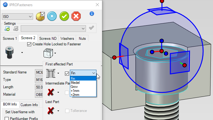
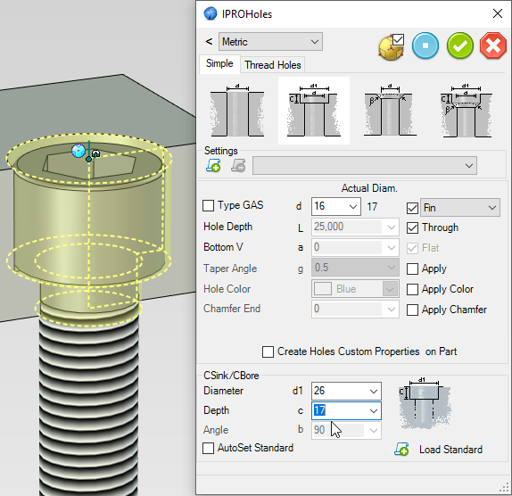
Currently, there's no option to control the depth of the counterbore for a hole which is created at the same time as the Screw/Bolt. I don't think it is a very common request, but maybe it could be added as an option. Though you can manage the size of the hole diameter itself like Coarse, Medium, Fine or any value you would like the hole diameter to have, by editing the Holes dimension table (Diameters.dat, placed here: C:\Users\Public\Documents\IronCAD Mechanical\Norme\Holes). But the Hole (and counterbore depth) can easily be edited afterwards and then just move the screw down to the bottom with the TriBall.
-
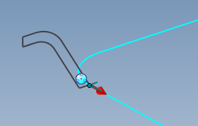
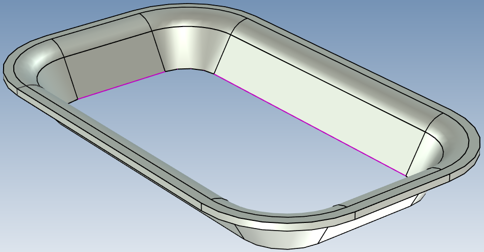
If you move the 2D Shape to the start of the 3D Curve it is easier to select and it seems to be working fine! Here's the model S&P tray_JB.ics The 2D Profile also worked fine, but I had to choose Link Profile to Path and set it with Profile Perpendicular to Path (the last two options on the image below).

-
The order or the Catalog Tabs are stored in the MS Registry and can be controlled with the IronCAD Mechanical add-on through the IPROSettings tool, which you can find in the Windows Start menu. As Kevin says, you can of course always alter the current order in the active session. But the "dragged tabs" order isn't stored in the registry. Next time you start IRONCAD the order will be as the Registry says, no matter what you've done manually in the previous session. Over time, as you open and close catalog files (tabs) the order of those files in the registry can sometimes become a bit messed up. You can read more about the IPROSettings tool, and how to manage the order of the Catalog tabs, here: http://ironcad.it/learnICM/en/basics/configuration/
-
The IronCAD Mechanical add-on web page recently got a big update with a nice list of new features and functions! You simply must check this out - http://ironcad.it/learnICM/en/news/ Don't forget that it also acts like a vast "online manual" for all the existing tools - http://ironcad.it/learnICM/en/
-
how to do cross break on a sheet metal in Iron cad
Jonas@Solidmakarna replied to a topic in Tips and Tricks
Please correct me if I'm wrong, but the Cross Break functionality in the Sketched Bend is currently aimed for Corrugated Paper models and making kind of "etch lines" for the cutting knife - where it shouldn't go all the way through the paper material. It can of course be used for simple etch lines on Sheet Metal too (but it won't bend the plate) and there's a request to make it a stand alone tool (Etch line) instead. The Sheet Metal Cross Break functionality that was originally asked about here (for a drop plate) does not (yet) exist in that way that it makes a "geometrically true" drop plate with cross break bends. That kind of tool is also something that has been discussed with R&D, but it isn't currently included in the short term update plans. -
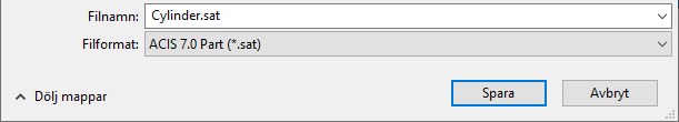
Carlo, try exporting an ACIS SAT v7.0 instead. I have tried this with a large assembly of a Steel structure to AutoCAD a few years ago and it came in really really good, keeping "solid blocks" with own attributes etc in AutoCAD, just as expected by the receiver of the models. ArchiCAD (by Graphisoft) is both different and similar to AutoCAD (by Autodesk), so I think it is worth a try!
-
Configurations with external link
Jonas@Solidmakarna replied to LEE MENG CHE's topic in General Discussion
No, that is currently not possible. But I have an enhancement request registered for that since before (Ticket #9834). I think that the function to be able to change the active configuration for an externally linked object was introduced in v10 (2007). But different configurations cannot be used for different instances (copies) of the same file. -
Cannot switch out auto select handle
Jonas@Solidmakarna replied to cborer's topic in General Discussion
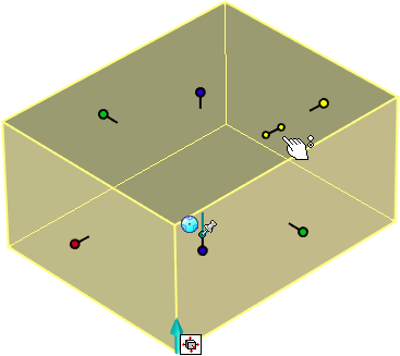
The symmetrical toggle button will show you what to toggle to next, not what it currently is. I agree that this is a bit confusing and we have spent many support calls explaining this to users. This is another reason why we have deactivated the toggle button in our localized Swedish installation. Using the right mouse button or [Ctrl] select Sizebox handles are more stable ways and more predictable for most users (not all), but those ways are not self-explaining either. When the toggle button shows both "handles" as yellow - it is currently not symmetrical (only one Sizebox handle is selected and will move). Click and it will toggle to be symmetrical (both handles will move). When the toggle button shows one "handle" as yellow and one as red - it is currently symmetrical (both Sizebox handles are selected and will move). Click and it will toggle to single direction (only the selected handle will move)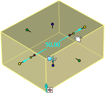
-
Configurations with external link
Jonas@Solidmakarna replied to LEE MENG CHE's topic in General Discussion
A Configuration in the 3D Scene is a type of filter (it can control suppress on/off and/or the XYZ position in space - per Object) which is stored within the ICS container file. Since you haven't stored the open 3D Scene as an ICS file yet, the configuration that you have made isn't stored anywhere either. Always start with saving the file you are working with, before saving out external links from it. If you then open a new empty 3D Scene and run Insert Part/Assembly to insert the first stored ICS file into that new ICS file, you can reach the configuration like you expect in the Scene Browser tree structure. So, the right click option under the link in the Scene Browser can be used to change configuration when the ICS file has been inserted into another ICS (3D Scene) file. Note: When saving all the content (the single assembly with all parts in) of a file to a new ICS file there's a risk of getting a Circular Reference (an ICS file which content looks for another ICS file (itself), which looks for another ICS file (itself), which looks for another ICS file (itself) and so on forever. Usually this can only happen when you manually change the ICS file name from the MS File Explorer, when IRONCAD is closed). This is almost a bit "philosophical" and quite hard to explain in text in an easy way, so please let me know if you have any questions -
STEP file; how to switch back to this mode?
Jonas@Solidmakarna replied to jake5564's topic in General Discussion
I would recommend you to always start IRONCAD first -> then create a new 3D Scene -> then run the Import Geometry function. When you double click on a file in Windows, it will be opened by the program that Windows thinks is the "most suited" and it might not be IRONCAD! An ICS file is also an MS Calender file... and the IronCAD Design Collaboration Program Suite consists of 4 programs, of which one is the free "3D Viewer" IRONCAD COMPOSE (which is probably one of the two cases that you describe), which has limited functionality when it comes to manage the models and making measures.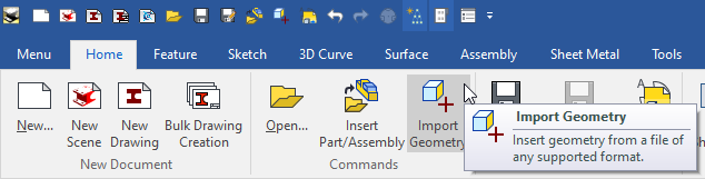
-
Cannot switch out auto select handle
Jonas@Solidmakarna replied to cborer's topic in General Discussion
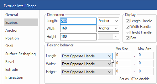
If you remove the toggle button for symmetrical control (by dragging with the left mouse button only) under Options, Interaction. This means that you can now still manage the round Sizebox handles in a symmetrical way, but instead of toggle it on/off by a button, you can do it in two other ways; a) Use the right mouse button while dragging a Sizebox handle to get a symmetrical effect on either the Length, Width or Height handles. b) Hold down the [Ctrl] key and select (any of) the Sizebox handles that you want to drag simultaneously. I am not 100% sure, but I have seen issues where the "symmetry function" stays active also when you don't expect it. But I have only seen this effect when the toggle button has been active (visible). I have never seen the symmetry staying active also afterwards when dragging with the right mouse button or using the [Ctrl] key. If you find that a shape "stays symmetrical" even though it shouldn't, have a look under the IntelliShape properties and make sure that the Resizing Behaviour for the handles are set to From Opposite Handle (not About Sizebox Center = symmetrical).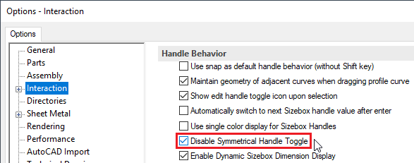
-
Cannot switch out auto select handle
Jonas@Solidmakarna replied to cborer's topic in General Discussion
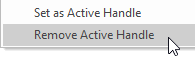
This is set on the shape (icon) that you drop from the catalog. You can right click on the shape icon in the catalog and choose Edit Catalog Item. Then remove the setting by right clicking the Sizebox handle of the shape that is now opened in a 3D Scene and choose Remove Active Handle. Then save and close the 3D Scene (which "is" that icon within the catalog that you chose to edit). Here in Sweden, we have made our own Starter catalog where the Active Handles are not set for any of the default shapes, except for the shape H Cylinder Through, where the diameter is the only value you can edit as there are no other handles. I really like the concept of Active Handles, but only when I myself choose to use them on shapes where it makes sense. I don't (personally) appreciate that someone else has set a certain handle as "active" for me, everytime I use a Block or H Cylinder etc. Carlo, you can try our customized Starter catalog and just remove the junk in it that you don't want to keep. Some folder names are using Swedish and can be easily renamed (if you still want to keep that specific icon but also read what it is ). Starter.icc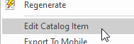

-
Cannot switch out auto select handle
Jonas@Solidmakarna replied to cborer's topic in General Discussion
Carlo, check under Options, Interaction.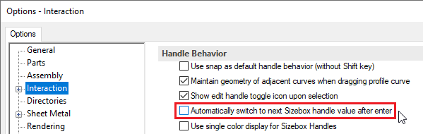
-
Your own suggestion of making the "notch as one piece" (a standalone part) which is later boolean as its own feature (as a brep shape) within the flat plate is quite good! It probably won't solve it completely (like blends in intersections) but very close and quite fast and easy to make. Without actually seeing the exact shape I cannot guarantee it, but I think you probably can make that "shape" of all those features using less number of features and also using the concept I showed in the video with IntelliShape bevel and even draft faces. I'm pretty sure you can do this with maybe 2-3 features and then use the TriBall to CopyLink them by clicking once on each switch below. If it was a "regular pattern" you could of course have used a Pattern Feature instead of the TriBall (though it does have an "instance/sketch point" option too, but then you would need each switch to be represented by a point on a sketch).
-
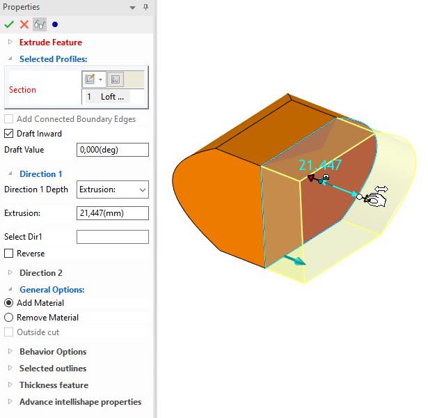
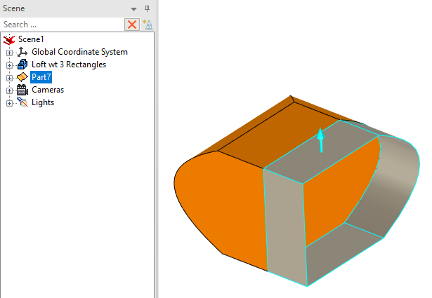
As Cary said, you can use more of the IntelliShape functions to include a Blend/Chamfer and even Shell and other functions within an extrude feature. An "IntelliShape" is an Extrude with extra "enriched" functions, it's not only the "stretching" Sizebox handles that are added. Remember that the TriBall can work with "standalone" features, such as positive/negative Extrude, Spin, Sweep and Loft shapes within a Part. When it comes to features that are based on (and only existing because of) a certain Face/Edge/Point ID number, such as Blend, Chamfer, Draft and other similar features, you can't use TriBall to move/copy (you wouldn't try to activate the TriBall for a Blend feature). You will always have to select and define the new edges (which will be created by a new hole) for the existing Blend feature. Also remember the order of the features under the Part. The Blend feature then must be placed after the new hole that was created, of the hole moved up in the Part structure before the Blend feature. I wouldn't always want to get Blend features copied with selected holes (if that was possible), but maybe if it is possible to implement such a function in the future - it could be an option. Here's how to make a "more rich" hole feature using IntelliShape properties. Copy a Hole with Radius.mp4 (I should have renamed the hole in the Scene Browser first instead, then the name would have followed to the Catalog item and to all the new features created by it).
-
There are probably good answers to all your four questions, but I've made a simple video with one easy way to make it. You don't have the same control over the match points, but using Associated Faces is a good way to approach it. At least very fast and easy. Also make sure you're using the ACIS kernel! Loft_AssociatedToFace-ACIS.mp4 Loft.ics

