Leaderboard


Popular Content
Showing content with the highest reputation since 05/01/2024 in Posts
-
Hi TaeGyu, The attached video demonstrates how to edit your particular model using the "Add Closed" tool. It also demonstrates Kim's previous comments regarding not being able to select multiple faces. Since multiple face selection works correctly for regular sheet metal parts, there might be a selection bug or limitation when sketch bends are used (like in your part). Malcolm Sheet Metal - Sketch Bend - Add Closed.mp4 Sheet Metal - Sketch Bend - Add Closed - Modified.ics3 points
-
One frustrating aspect of merging item bubbles in CAXA is that they disassociate themselves from the view they are attached to. However, I stumbled across a second method for creating merged item bubbles which keep them associated to the view. This was New to me so I thought I would share in case its also new for anyone else . Peter Merging item bubbles in CAXA.avi2 points
-
Hi Jang, It depends on which face what you clicked in Extend box. You can see the only one face shows the opposite color in your sample(0:13). bandicam 2024-05-24 18-03-20-869.mp4 Sheet_Metal.ics Well...it is funny that I can't add more faces to Extend Box of the Closed Corner with IC2024#PU1. I didn't know it Kim2 points
-
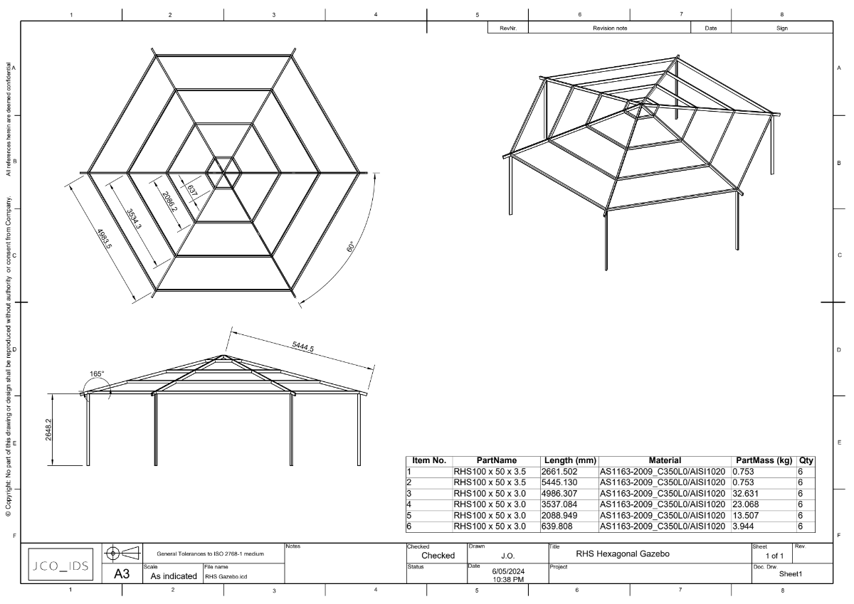
This is an option to structured frames. The StockRHS_ANZS catalog is based on Australian and New Zealand RHS sections. Hexagon Gazebo.pdf IronCAD Blue_Datum+Profile.ics RHS Gazebo.icd RHS Gazebo.ics StockRHS_ANZS©.icc
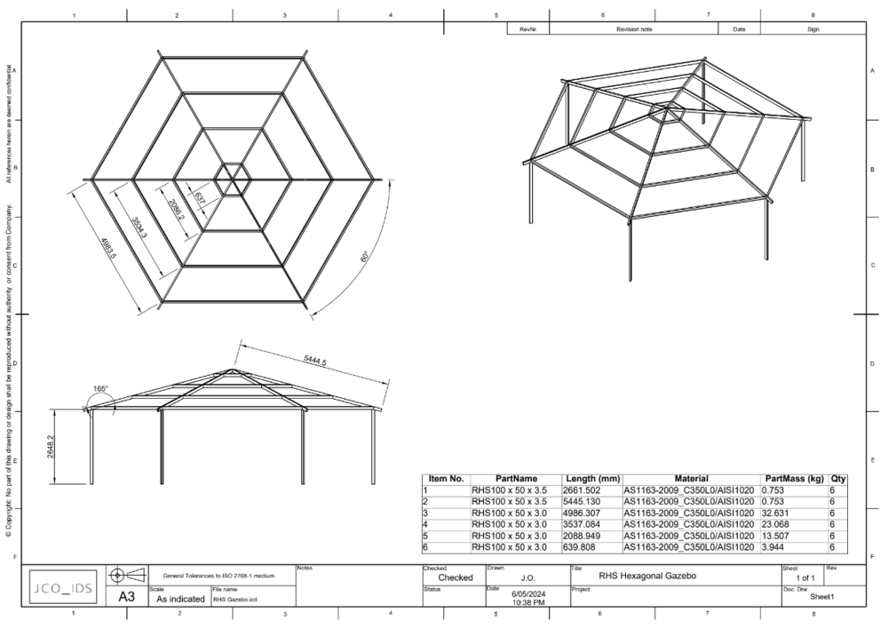 2 points
 -
Hi Harley, If you select or highlight your assembly in the scene browser and select "Save As" from the File drop down menu you will get that option like you said to check the box "As Copy (Without affecting open files)". Then if you check the box and select "Save" you will get a box with these two options. 1. If you select "Copy all linked files to the new assembly file directory" and hit OK then you will get another copy of the assembly with all of the linked files where you save them. Example: If you want another copy of the assembly with all of the files in a new folder. 2. If you select "Do not process linked files" - you will get another copy of the assembly without any of the linked out files. Hopefully that answers your question. The other choice is if you don't select the check box "As Copy" (without affecting open files). Then there are more choices but it gets more complicated. Doug
selected.png.582434f80730b70a851fe59453319dde.png) 1 point
1 point -
Hi Malcolm, Another benefit is for adding items such as adhesives or thread locking compound ect. I usually add these types of items to the B.O.M using the 2D "generate item No." and hand enter the information into the B.O.M. rather than trying to model that stuff. so as an example it is now easy to add thread locking compound to the item callout along with the fasteners. Pete1 point
-
Import Options.mp41 point
-
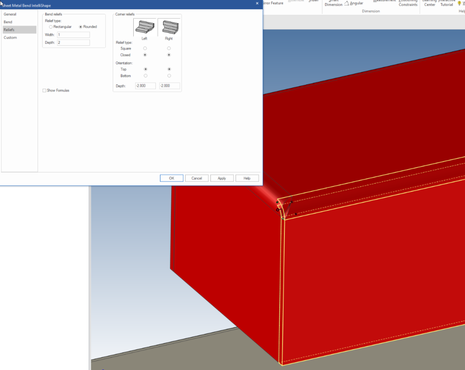
Hi tgjang, You've made a rod for your own back by trying to mix sketched bends with closed ends unfortunately. I have made your box with the closed ends you require using just sheetmetal stock, applying the bends ( not out bends or in bends ) and then treated the reliefs as you will see when you explore them. Click on the bend to get intellisahpe level, use TAB then right click on one of the little diamonds, click ben properties, reliefs and change your Corner reliefs. This gets fast after you use it several times. You could use The 'sheet metal - Add Closed' tool as well and choose 'overlap'. Sheet_Metal.ics
 1 point
 -
Hi sondc, The "limits" option is only available when the SmartDimension is "Locked". Referring to your image, simply select "Lock" and then the "Limits" option will appear. Malcolm1 point
-
I reinstalled it - seems to have solved the problem. thanks for your help1 point
-
This toggle should allow you to enter a different PN and keep the link:
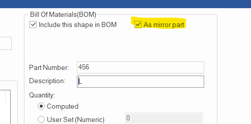 1 point
 -
Dear Kim Great - thanks a lot for this! This is indeed somewhat better than what I had but still an iterative trial&error procedure with a lot of fiddling. I'm hoping/looking for a more deterministic approach (as you propose in the other thread)1 point
-
Ironcad+woodlab on mac. We use two drive
 1 point
 -
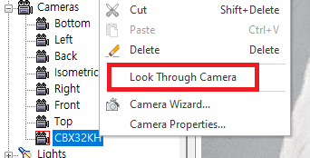
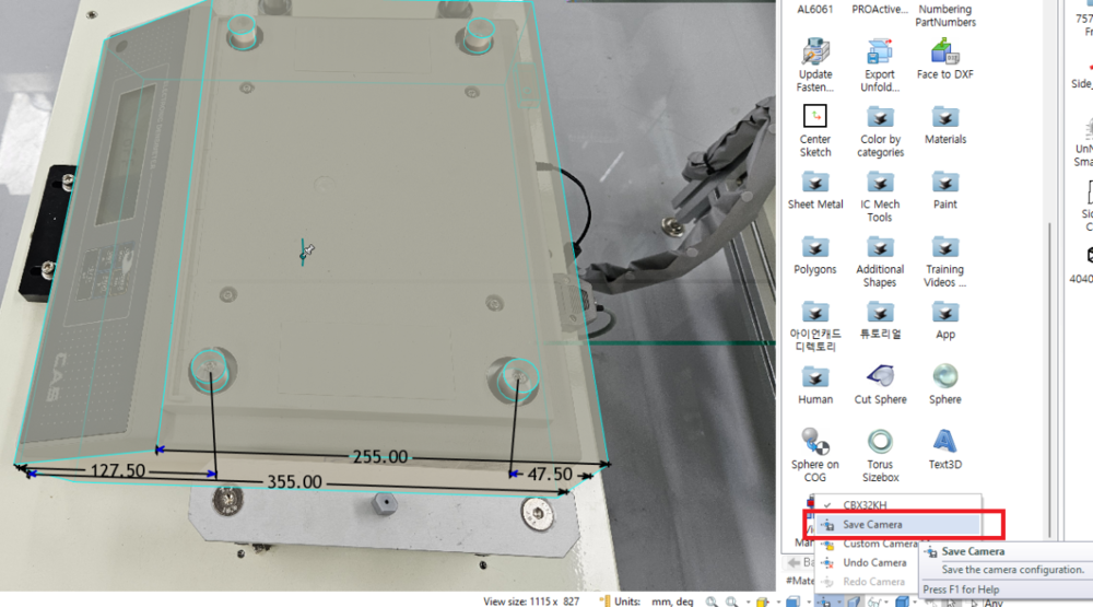
Hi Ludin, For Super Perspective Camera, you need to edit it in the camera's properties. And the "View Manager" in ICM tools that controlling View by numeric would be help for aligning the object to the picture. See the attached photo below. bandicam 2024-05-07 11-45-15-563.mp4 Did I guess it right? Edit) Don't edit the properties of the default Camera, Copy & Paste that camera and edit properties in that. Field of view angle : Zoom value Position : This is the X, Y, Z camera position that is related to the Far away~~ value of the camera wizard. Select a camera and choose Look Through Camera from the pop-up menu to change the active camera. Once you're happy with the result, be sure to save the current screen with “Save Camera” - this saves the location you are currently viewing (Camera), not the values associated with the camera properties. Kim
 1 point
 -
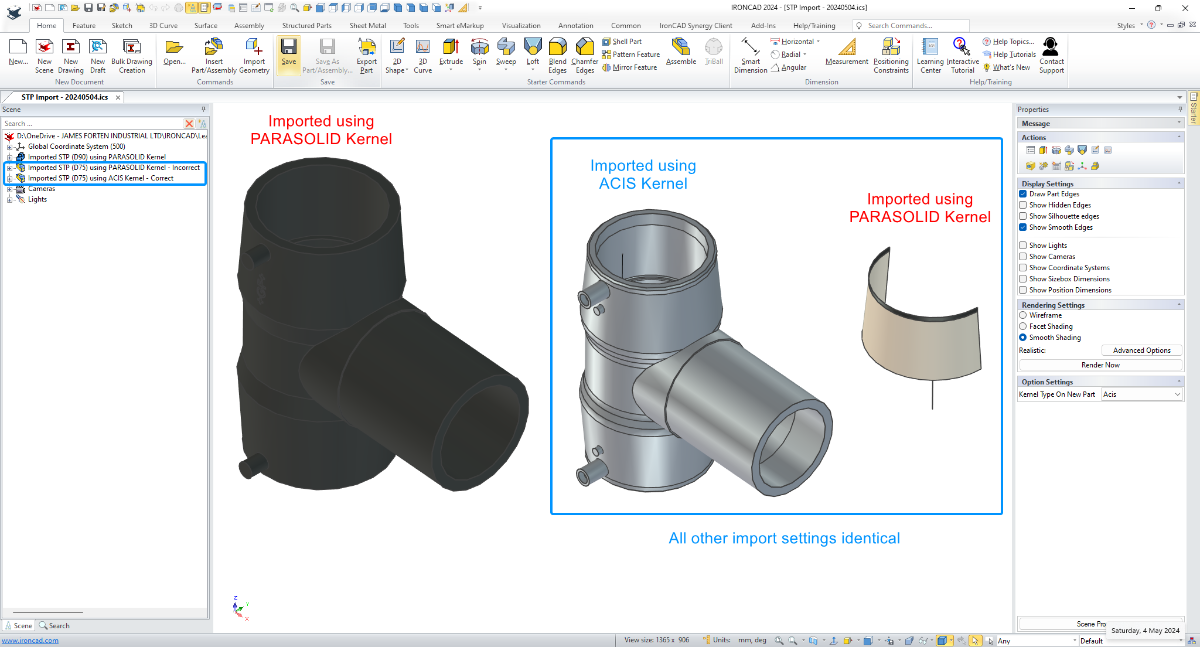
In this example I'm importing two STP files received from the same supplier. For one of these parts, it was necessary to set the Scene Kernel to ACIS for it to import correctly, whereas for the other part it imported correctly when the Scene Kernel was set to PARASOLID. So even though these came from the same supplier, the CAD software used to create or export these may have been different. Hence the different results. Malcolm STP Import - Changing Scene Kernel - 20240504.mp4
 1 point
 -
I see this too in Groups coming from IronCAD 2023. Bug report filed, QA 818601 point