Search the Community
Showing results for 'structured part' in content posted by Malcolm Crowe.
-
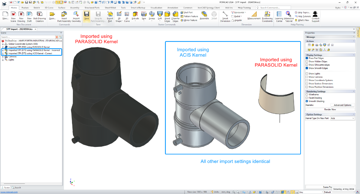
 In this example I'm importing two STP files received from the same supplier. For one of these parts, it was necessary to set the Scene Kernel to ACIS for it to import correctly, whereas for the other part it imported correctly when the Scene Kernel was set to PARASOLID. So even though these came from the same supplier, the CAD software used to create or export these may have been different. Hence the different results. Malcolm STP Import - Changing Scene Kernel - 20240504.mp4
-
Hi TaeGyu, There have been positive improvements regarding Structured Frames within recent releases, and there are many potential applications for it; but in my opinion additional enhancements are needed before I'd start showcasing it to users. Perhaps some of those enhancements will arrive in IC2024 PU1 or IC2025 or ....... (I don't know what R&D are working on). In answer to your questions. 1. Sometimes I like to toggle between displaying and exporting Solids and 3D Curves (as part centerlines). This is a huge benefit offered by Structured Frames (and Structured Parts). In these applications I will include 3D Curves, but these are normally "Extracted 3D Curves" from a 2D Sketch. 2D Sketches provide better control and can be driven using parameters. While the 3D Curve tools have been greatly improved recently, they also require additional enhancements to provide the level of control needed. As a result, these aren't my preferred tools. 2. It is very rare that I need to create a Datum Plane (but I'm pleased to have the capability for when I do). You don't need Datum Planes to create 2D Sketches. For example, in your model the Datum Plane wasn't necessary, as the "Sketch Position" tools provide that positioning functionality relative to the XY, XY, and YZ Planes of the Part. 3. For some projects we export the CAXA BOM to Excel Spreadsheets for the reasons that you have listed. All of our BOM Styles contain all of the properties that we might want to display or export. But we control what is displayed in the drawing by controlling the width of the BOM item within the BOM Style. A width of zero (0) means that it doesn't display. Regardless of what is displayed in the BOM on the drawing, when the BOM is exported from CAXA, all of the columns are exported to the Excel Spreadsheet. Malcolm
-
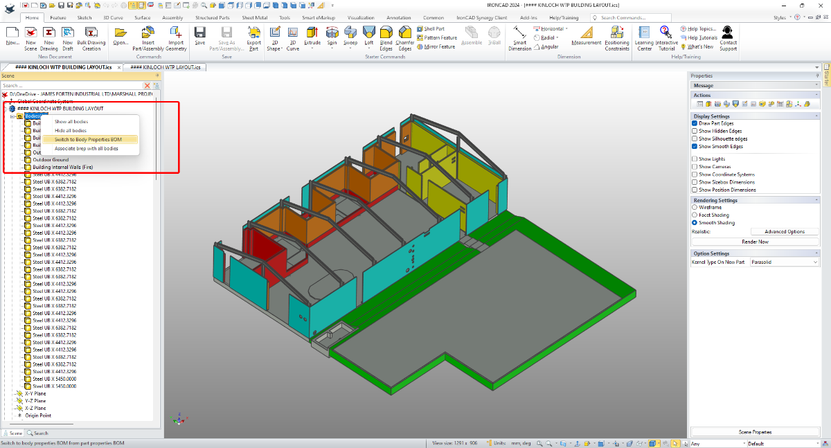
Hi TaeGyu, I'm pleased that it helped. Regarding any Application being written for extracting Part Properties from multi-bodied Structured Parts, it's important to reference the "Switch" between Part and Body Properties. This "Switch" was introduced in IC2024. It you're not familiar with this, see the attached video. Malcolm Switch Between Part and Body Properties BOM.mp4

-
Hi TaeGyu, In the attached video I demonstrate how to apply the requested properties (Description and Material) to the individual Frame Members (Bodies) of the 3D model, so that they then appear in the BOM of your CAXA drawing. I also show how to get the Qty to display and total correctly within the BOM. I hope this points you in the right direction. Malcolm Structured Frames - Bodies in BOM.mp4 STEEL_TEST - MC.exb STEEL_TEST - MC.ics
-
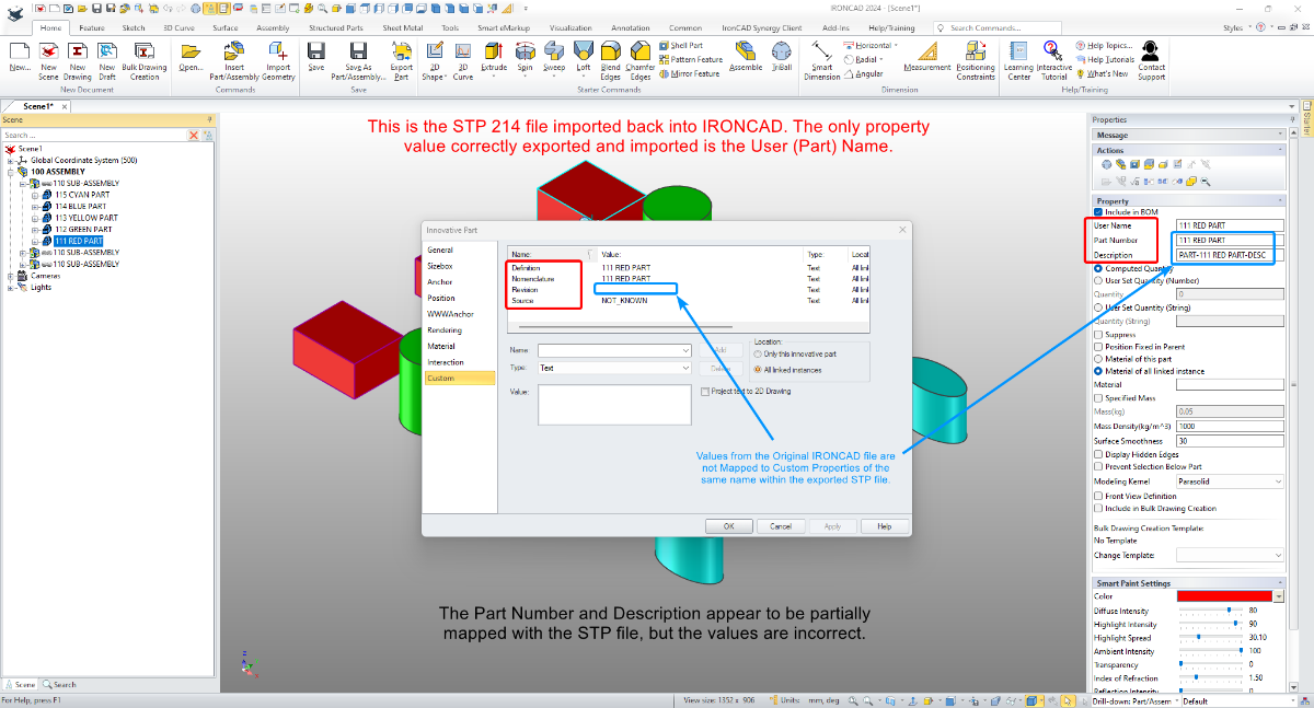
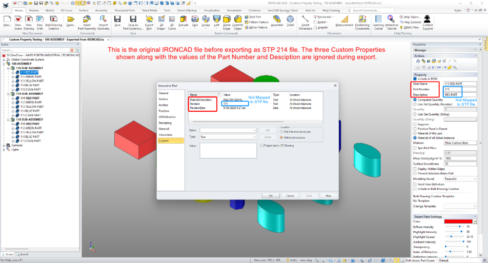
Attached is an image of an IRONCAD file in which I have added three Custom Properties (MaterialDescription, Revision, RevisionDate). Also attached is an image of this file after it has been exported as a STP 214 file and imported back into IRONCAD again. 1. The original Custom Properties are ignored and replaced with others (Definition, Nomenclature, Revision, Source). How can we stop exported STP files from including unwanted Custom Properties, and is there a way to filter what is imported? We currently manually remove these from imported parts and assemblies. 2. How to map the values of the original Custom Properties (Part Number, Description, Revision) to the same Custom Properties in the exported STP file? The exporting process seems to ignore the original Custom Properties all together. Malcolm Custom Property Testing - 100 ASSEMBLY - Exported from IRONCAD.ics Custom Property Testing - 100 ASSEMBLY - Exported from IRONCAD 214.stp

-
CAXA - Broken out section on isometric
Malcolm Crowe replied to PWATSON's topic in General Discussion
Hi Logan, The important thing to keep in mind regarding "Assembly Features" is that they are Features (Intellishapes). Therefore when you create Configurations for controlling the suppression state of these, you need to select the option "Track suppression of Intellishapes ...". See the attached image. I've also attached a video demonstrating the process. Note that this isn't the only way, but it is the easiest. The other way doesn't require this option selection; but it involves setting up Suppression Parameters and Design Variations. This is more involved, which is why I've chosen not to demonstrate it, Malcolm Assembly Features - Suppressing - Configurations.mp4 Assembly Features - Assembly.ics Assembly Features - Red Part.ics Assembly Features - Yellow Part.ics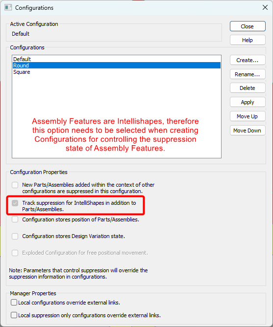
-
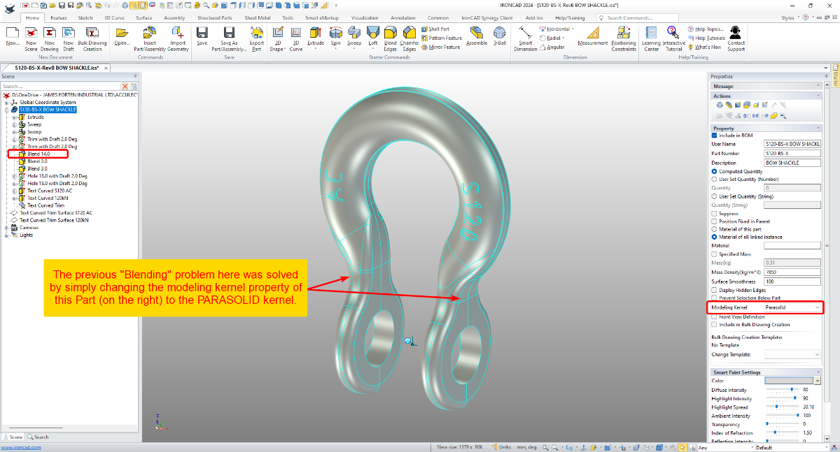
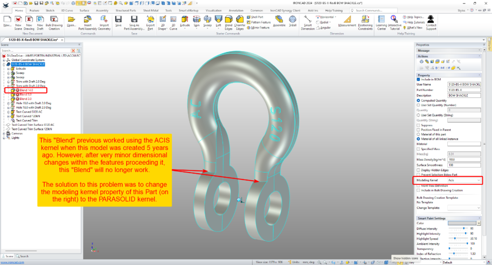
This is an interesting example from yesterday, where it was necessary to change from the ACIS kernel to the PARASOLID kernel for some Blends to work. This model was originally created 5 years ago (using the ACIS kernel), but after some very minor dimension changes yesterday, these Blends stopped working. Changing the kernel property of the Part to using PARASOLID solved the blending problem. Malcolm IRONCAD - Blend Problem Solved Changing from ACIS to PARASOLID Kernel - 20240313.mp4

-
If you have multiple "Structured" Parts that you want to combine into a new single Innovative Part (or Structured Part), the attached video demonstrates how to do this using the "Copy Body" tool. Malcolm Structured Parts - Combining Multiple Parts into One.mp4
- 1 reply
-
- 2
-

-

-
Many users will be familiar with creating "Patterns" using the TriBall or perhaps the "Pattern Feature" tool. But another option is using "Sketch Patterns" within 2D Sketches. This is especially useful when used with the "Structured Frame" tool. Attached are a couple of videos demonstrating what's possible. One example uses Parameter Expressions to calculate an "Equal Distance" between Patterned Objects. Whereas the other example uses Parameter Expressions to calculate an "Equal Gap" between Patterned Objects. Malcolm Structured Frames - Sketch Pattern - Equal DistanceX.mp4 Structured Frames - Sketch Pattern - Equal GapX.mp4
-
Within a "Structured Frame" (or any multi-bodied Structured Part) it isn't possible to directly suppress a "Body" (like we can with "Features"). However, it is possible to add "Delete Body Features", that can then be suppressed and unsuppressed. The end result being the same as suppressing the Bodies. This is demonstrated in the attached video. Malcolm Structured Frames - Suppressing Bodies (Members).mp4
- 1 reply
-
- 2
-
-
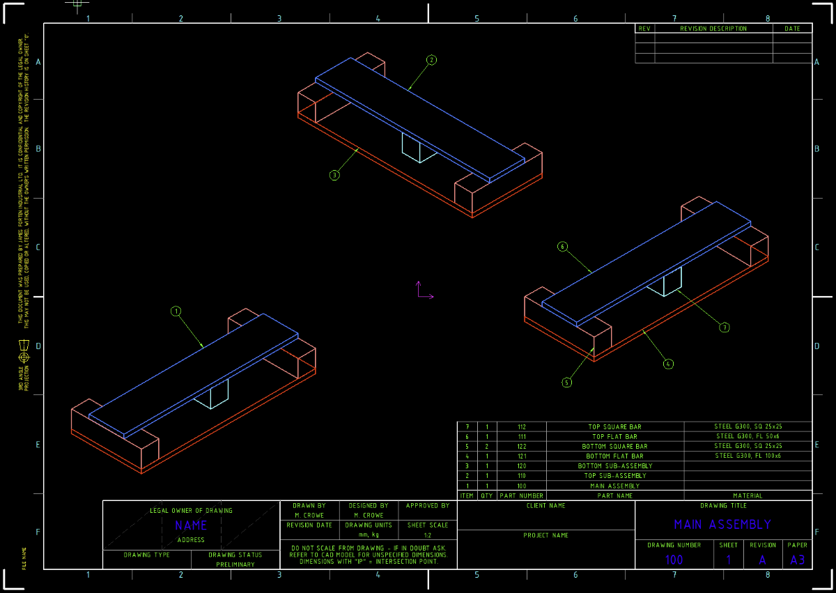
Within the "Structured Parts" tab of the Ribbon Bar in IRONCAD 2023 is a panel named "Structured Frames". This was previously named "Steel Frame" and is similar to "Weldments" within SOLIDWORKS. Structured Frame "Features" are inserted into Structured Parts, and within these "Features" are "Bodies" (Frame Members). The purpose of this post is to make users aware of the influence Structured Frames have on the Bill of Materials (BOM). Normally, the BOM references the "Part Level Properties" of a Part or the "Assembly Level Properties" of an Assembly. As soon as a "Structured Frame Feature" is inserted into a Structured Part, the BOM stops referencing the "Part Level Properties" of that Parent Part, and instead starts referencing the "Body Level Properties" of the Frame Members. As a result, the Parent Structured Part is no longer treated as a Part (or Assembly), but as an invisible Construction Object or Container (for lack of a better word). In the attached video I have tried to demonstrate this. Page 3 of the attached reference document also covers this. Malcolm Structured Frames - Bodies (Members) Displayed in BOM.mp4 IRONCAD - Structured Frames - 20230312.pdf
-
The intent of the attached document “Structured Parts – Key Differences” is to provide a basic understanding of "Structured Part Modelling". Within the videos of the following posts, I’ve tried to convey the basic concepts in a clear way (such as Sketch Positioning, Features and Bodies), while also trying to provide a little “taste” of how Datums, 3D Curves and Surfaces can be included for construction purposes. I've also tried to demonstrate how to use the Feature Structure (Rollback State) to create the desired associations, as well as demonstrating how to work with multiple Bodies. 01 - Coordinate System 02 - Bodies and Features 03 - Edit Sketch Position (Positioning Shapes) 04 - Edit Sketch Cross-Section (Profile) 05 - Datum Plane for Draft Neutral Plane 06 - Mirroring Bodies using Datum Planes 07 - Creating and Positioning Another Body 08 - Adding Datum Axis for Circular Pattern of Feature 09 - Splitting Body using 3D Curve and Surface Body 10 - Setting Different Colors to Bodies 11 - Using Datum Planes for Trimming “Structured Part Modelling” is really important for creating complex Multi-Bodied models (which can't be created as "Innovative Parts"). Having said that, the multi-bodied part in the following demonstration videos is not a complex model. This is simply to demonstrate some basic concepts. There is a separate forum post regarding real world "Structured Parts - Examples". Malcolm IRONCAD - Structured Parts - Key Differences (Document).ics IRONCAD - Structured Parts - Key Differences - 20230210.pdf IRONCAD - Structured Parts - Key Differences (Videos).ics
-
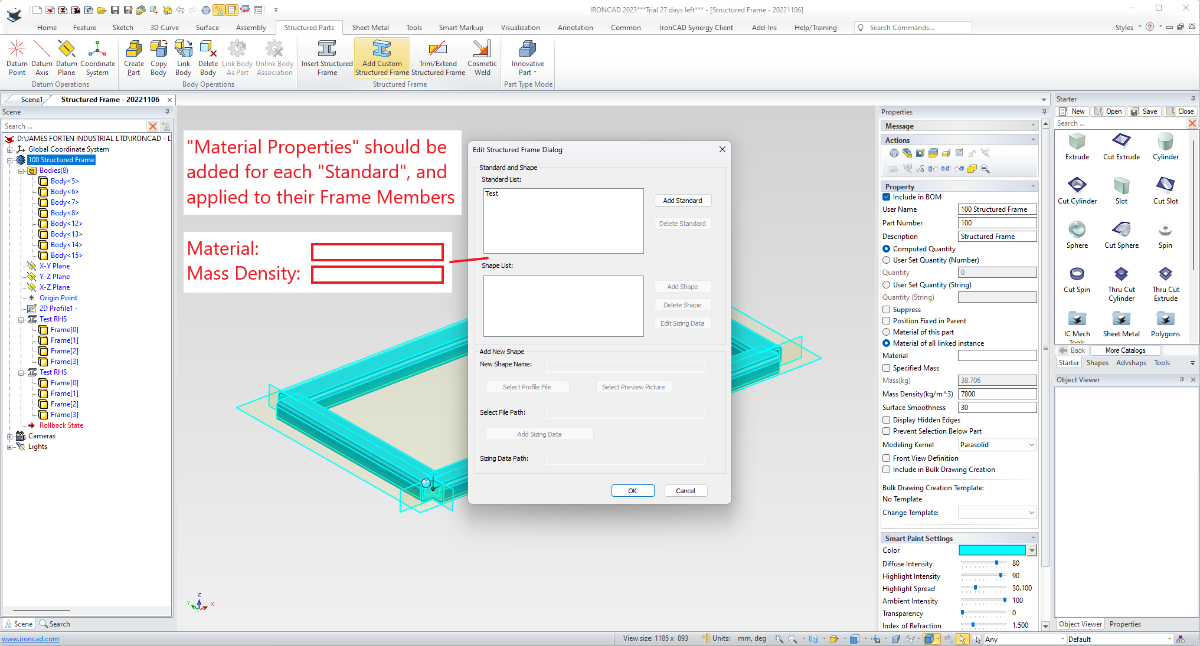
Within the "Structured Parts" tab of the Ribbon Bar in IRONCAD 2023, within the "Structured Frame" panel, a new tool has been added named "Add Custom Structured Frame". This newly added tool enables users to add their own Custom Shapes based on 2D Sketches and Size Data (which can be entered directly or imported from an Excel Spreadsheet). In the attached video I have tried to demonstrate the process involved. Pages 4 - 6 of the attached reference document also covers this. Malcolm Structured Frames - Adding Custom Shapes and Sizing Data.mp4 IRONCAD - Structured Frames - 20230312.pdf
-
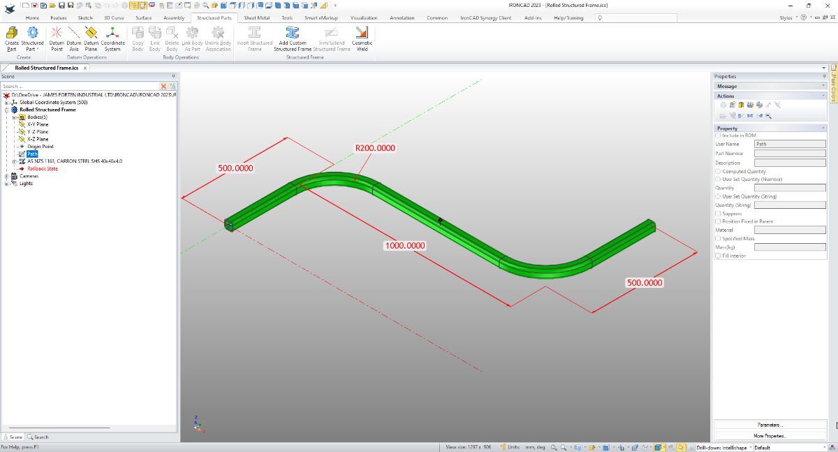
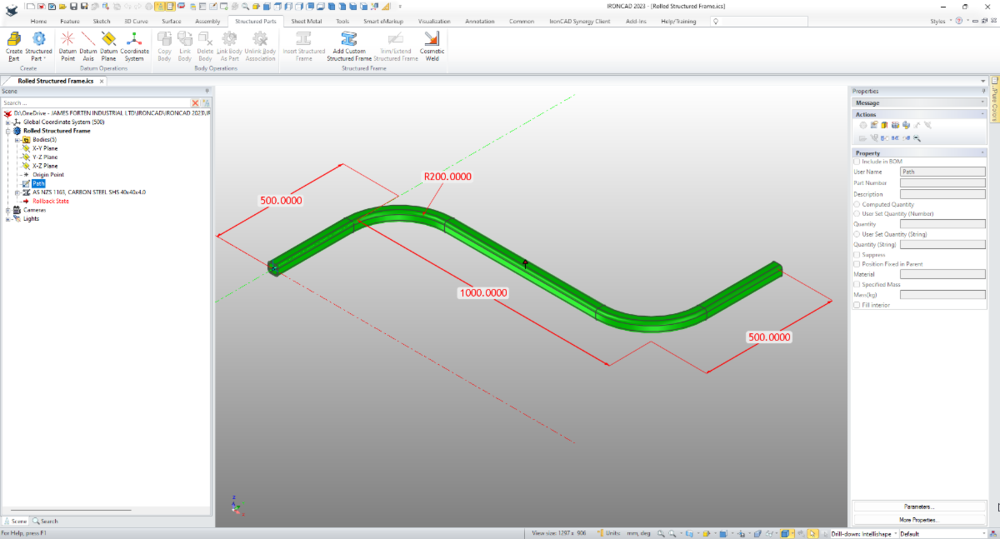
The "Structured Frame" tool is well suited for this. Create a new "Structured Part" and within that create a sketch of the "Path" that you want the Structured Frame to follow. Then use the "Structured Frame" tool to apply the desired section to that sketched path. See the attached video. Malcolm Rolled Structured Frame.mp4 Rolled Structured Frame.ics
-
This is an example of how to combine multiple Imported Parts (whether Innovative or Structured) into a single Part using the "Copy Body" tool. Malcolm Copy Body - Combining Multiple Parts into One.mp4
- 1 reply
-
- 3
-
-
-
For those interested, attached is a document describing the 3 different modelling modes within IRONCAD (as listed below), and how these relate to the common modelling approaches used for 3D modelling (that is, "Direct Face Modelling" and "Feature Based Modelling"). 1. Innovative Part Modelling - Offers Greater Freedom (best suited for simple single bodied models) 2. Structured Part Modelling - Offers Greater Functionality (best suited for complex multi-bodied models) 3. Sheet Metal Modelling - Sheet Metal Specific It is a common mistake among IRONCAD Users and Resellers that "Innovative Part Modelling" is somehow better than "Structured Part Modelling". That simply isn't the case. There are many parts that simply cannot be modelled using "Innovative Part Modelling" (multi-bodied parts being the obvious example). The strength of IRONCAD is that you can choose the modelling mode that is best suited for what you're trying to model. The link below shows some examples of where "Structured Part Modelling" has been used. The models themselves are not attached though. Malcolm IRONCAD - Modelling Modes - 20220912.pdf
-
This tip is regarding how to combine different assembly and part "levels" within the same Bill of Materials table within CAXA, and the associated "Item Numbers". CAXA only allows the user to select a single "level" (grade) for each source BOM file. However, CAXA allows users to import multiple BOM source files, where each source BOM file can then be set to display a different level. The end result is that you can achieve a single BOM table that displays items from different "levels" within the 3D scene. It isn't possible to import into CAXA the same named source file more than once, so it's necessary to create multiple versions of the same 3D scene with different names. This can be easily done by creating a new scene, and inserting the original scene into it (as an externally linked file) and saving it with a meaningful name (such as ....... BOM Level 2, ..........BOM Level 3, etc). Any changes made to the original file are reflected in the other BOM Level source files. While the BOM Table can display these combined levels, the "Item Numbers" for each generated view cannot. So each generated view needs to display items at a single level. To do this, each view needs to be generated from the correct 3D scene source file. For example, if a generate view is to display "Item Numbers" for "Level 3", then the view needs to be generated from the ...... BOM Level 3 source file. Hopefully the above makes sense in the context of the attached video. Malcolm CAXA BOM - Combining Assembly and Part Levels.mp4

-
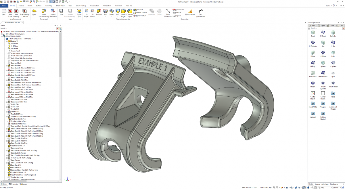
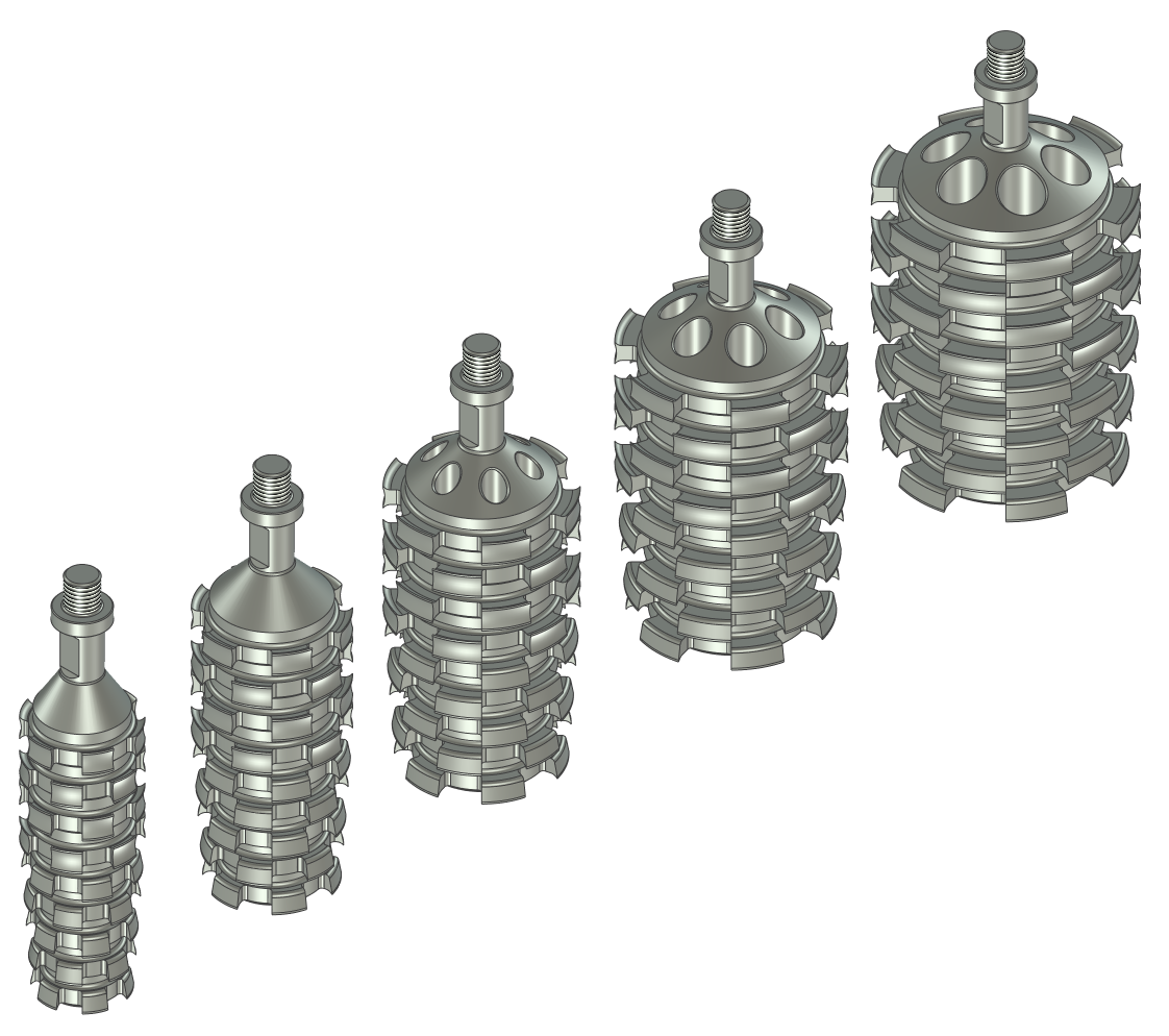
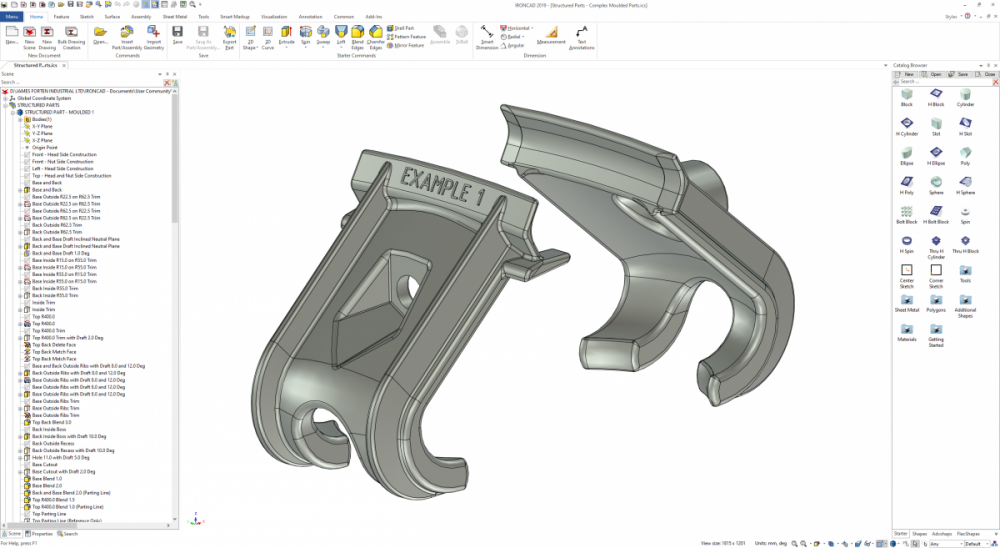
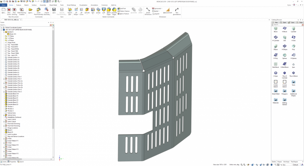
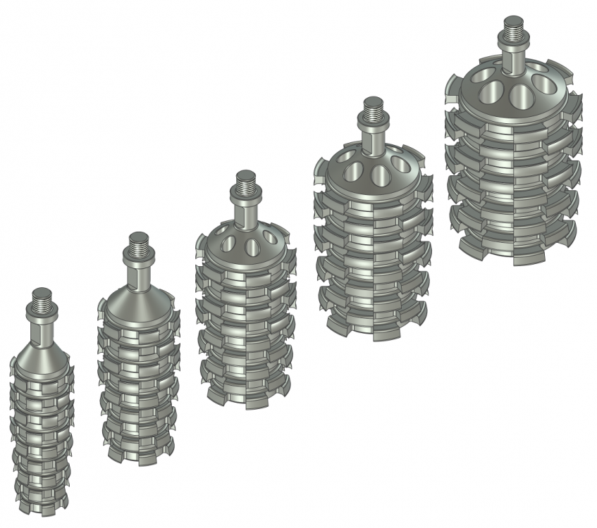
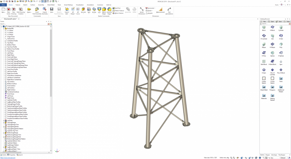
One of the key advantages of IRONCAD is that it offers users the option of working in either "Innovative" or "Structured" part modes. Personally speaking, "Innovative" is my preference for simple 3D models, as they are fast to create and edit. However, "Structured" is my preference for complex 3D models (and 2D layout sketches). These require more thought and take longer to construct; however, these can be easier and faster to edit (changing parameters) than "Innovative" parts and assemblies. Attached are some examples of "Structured" parts and assemblies. 1. Complex Moulded Parts (using multiple steps to construct the necessary features and draft angles) 2. Complex Sheet Metal Parts (using multiple construction elements within the part) 3. Parametric Part Families (family of parts based off common structured parametric part) 4. Parametric Assemblies (multiple associated "bodies" - that can be externally linked also) When you need to use construction elements (such as sketches, 3D curves, surfaces, and reference bodies), to help construct a complex part; then "Structured" mode keeps these construction elements within the part itself (and maintains the associations between those elements). Malcolm Structured Parts - Multi-Bodied Assemblies.mp4
-
Hi Vendel, I realize that this isn't exactly what you're after, but it provides another option (adding to what Cary has already suggested). That is, to save your original Part files as "Master Part" files, and then create new "Part" files (as Structured Parts) that have a BREP feature in them that is linked to the original "Master" files. If you save these new files as the original file names, all of your linked Assemblies across your many projects will automatically start referring to these new child files (that can't be easily edited). This is demonstrated in the attached video. Something that isn't demonstrated in the video (but that's necessary) is copying the Part Properties from the Master Part to the newly created Child Part. This can be done easily using the Eye Dropper tool. Malcolm Creating Master and Child Parts.mp4
-
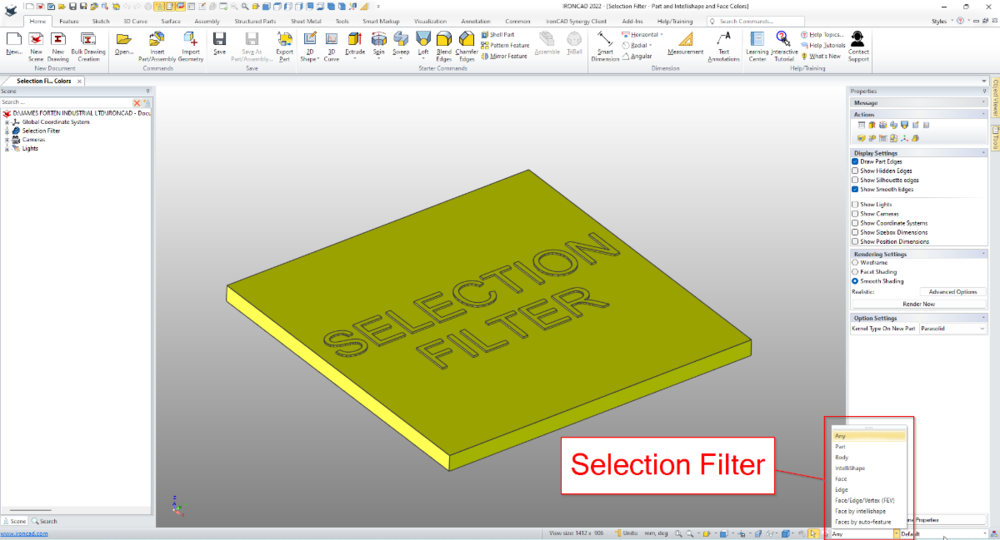
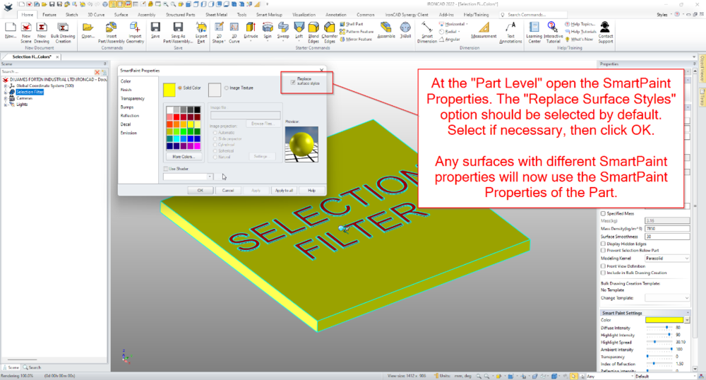
Within the 3D Scene of IRONCAD it's possible to apply different colors at the Part, Intellishape, and Face levels. This is especially helpful when working with multi-bodied (structured) parts, but also for highlight elements such as embossing or engraving. Located on the Status Bar (bottom right of the screen) is the "Selection Filter". This is useful for controlling what is selected during "box selections"; but it also includes useful filters such as "Faces by Intellishape" and "Faces by Auto-Feature". The attached video demonstrates how these filters can be used for selecting different elements, while also demonstrating how to apply different colors at the Part, Intellishape, and Face levels. Malcolm IRONCAD - Selection Filter - Part and Intellishape and Face Colors.mp4
-
Questions about Structured modeling with Skeleton
Malcolm Crowe replied to tgjang's topic in General Discussion
Because Bodies use the Coordinate System of the Parent Structured Part, if the Body reorientates within the Structured Part, the BREP within any externally linked Part will also reorientate in the same way. So, yes it will affect the Generated Views within 2D Drawings. However, if you use "Define Front View Definition" within the externally linked Part, and generate your 2D Views using that, then that should no longer be a problem. See the attached videos. Note that when Generating Views, it's critical to select "Associate to Front View Definition". Malcolm Structured Parts - Creating Part Drawings of Individual Bodies.mp4 Structured Parts - Using Front View Definition.mp4 TERMINAL CRIMPER - Part Drawings - Part 2.ics TERMINAL CRIMPER - Part Drawings.ics -
Questions about Structured modeling with Skeleton
Malcolm Crowe replied to tgjang's topic in General Discussion
Hi tgjang, I'm pleased that you made the effort to construct this, and congratulations on creating a Multibody Structured Part. Where you went wrong was that the very first feature needs to be your Skeleton Sketch (Layout Sketch). From there you then want to create a separate Sketch for each of the Parts, with each of these Sketches being associated to the Skeleton Sketch (and if necessary, any other Part Sketch before it). Then, you use these Part Sketches as the basis for constructing the solid bodies. This is explained in the attached video, but I'll create a separate video for you shortly demonstrating how to associate these separate Part Sketches to the initial Skeleton Sketch. So that everything follows any changes made to the Skeleton Sketch. Malcolm Comments regarding Termianl_Crimper-Skeleton-1.mp4 -
Questions about Structured modeling with Skeleton
Malcolm Crowe replied to tgjang's topic in General Discussion
Hi tgjang, I've just watched the video (as I was curious regarding PTC). The design process demonstrated seemed more complicated than is necessary with Structured Parts in IRONCAD. So, I don't recommend strictly following the methodology demonstrated in the video. What PTC describes as "Skeleton Parts" we (my company specifically) refer to as "Layout Sketches". We use "Layout Sketches" all the time for controlling the size and positioning of Parts. So, I understand the concept very well. However, there are a couple of different ways that this can be approached using Structured Parts. 1. Is to duplicate the process demonstrated in the PTC video. That is, with a separate "Skeleton Part" driving separate linked "Parts". 2. Creating all of the "Parts" as associated "Bodies" within a single "Master" Multibody Part. The principle of driving the size and position of everything from a "Layout Sketch" (Skeleton Part), remains the same for both options. In your attached file you have 2 Innovative Sketches that have no Projected Constraints between them. So, there is no association between the sketches. You have to understand how to use "Projected Constraints", as they are the basis of everything that you'll be doing within Structured Parts. Malcolm -
Structured frame - How can I edit density of blcok?
Malcolm Crowe replied to Bertrand Kim's topic in General Discussion
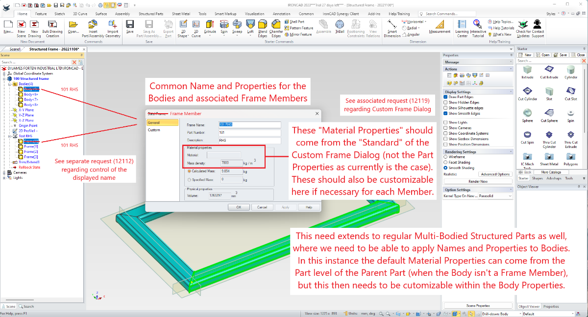
Hi Kim, The attached video demonstrates what Kevin is referring to regarding "Hidden Bodies" and the need to "Delete" them (at the end of the Feature Structure). Currently all "Bodies" (Frame Members) within a Structured Part adopt the Material Properties of the Parent Part. This isn't ideal, as it limits how this tool can be used. I have previously requested (tickets 12118, 12119, 12120, 12672) that Users have the ability to customize the Material Properties of "Bodies" (Frame Members) within Structured Parts. Hopefully these requests (and other associated enhancements) will be implemented sooner rather than later. Malcolm Structured Frames - Part Density is Applied to all Bodies.mp4

-
Hi James, The link below is to a previous Enhancement Request in 2020 (ticket 114048) regarding dragging-and-dropping Text Properties from a Catalog onto selected Bodies (Frame Members) within a Structured Part. In a separate Enhancement Request in 2022 (ticket 11891), I've also asked that Default Property Templates for Structured Frame Members be added within Options, so that Frame Members can be automatically populated with the desired Custom Properties during creation. Malcolm