Gigi
-
Posts
30 -
Joined
-
Last visited
Content Type
Profiles
Forums
Blogs
Downloads
Articles
Gallery
Everything posted by Gigi
-
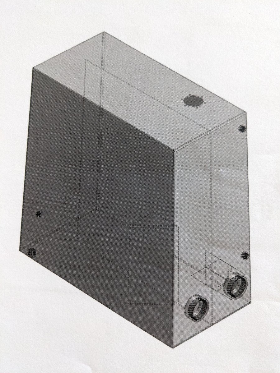
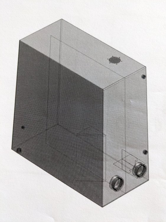
Here's a picture of the model. You can , I think, see the top, right side and bottom in this picture are one piece. The front , back and left sides are one piece. I need the front, left side and right side to be one piece while the back, top and bottom are another.
-
Here's my ICS. hydroRes_final.ics You can see, I made the three skinny sides one piece and the other piece is the two big sides with one skinny side between them. It can't easily be bent that way, and is less efficient with material (I think), so I was told it should be set up so each big side has one skinny side on each end of it. One big side with the two ends, the other big side with the top/bottom. It wouldn't really take much to start over, the main work would be placing the ports and internals. I think I can use the internal parts in a new scene, right? But the advantage of computer modeling is the flexibility to experiment and modify a design without much work. It seems like it would be very advantageous to be able to move bends around and iterate a sheet metal design with different bend/weld configurations to come up with the best solution. So why wouldn't you want to connect two separate pieces with a bend or remove a bend to make one piece into two? Maybe the feature is on the way? Any way, if it can't, it cant. Just need to find out.
-
Made a box with the sheet metal tools, then realized I set up the bends wrong. Rather than starting over completely, is it possible to join two sheet metal parts with a bend, and to separate a sheet metal paint at a bend into two parts? Basically, I need to swap around where the bends and welds are to make bending more feasible while continuing to minimize the welding. Any help on this is appreciated. I'm not finding anything in my searching but sometimes I don't know the right words for what I'm doing.
-
Not sure what you mean by that. Handles on an inteleshape? Doesn't that just modify the shape? I want to rotate it as it is. Maybe I just don't understand?
-
Ok, after a few more hours of googling, I think I figured something out. I found "rotate view to horizontal" Please let me know if this is it, or there's a better way or just a different one.
-
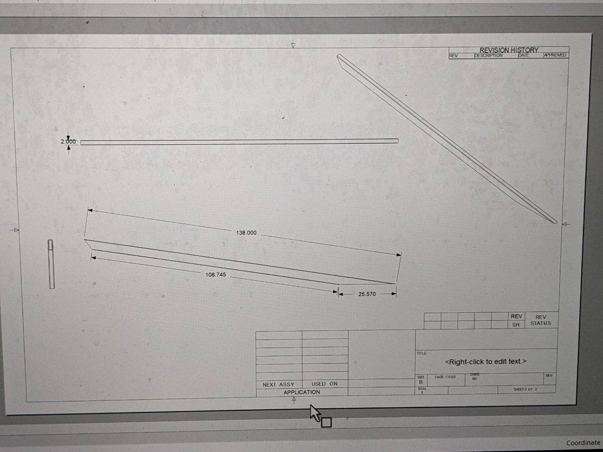
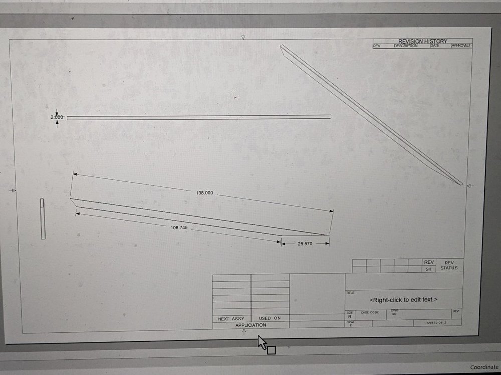
In an IronCad 2d drawing, how do I create a dimension between two points along a line that does not connect those points when that line is not horizontal or vertical? See photo, this will make sense I think. I want to mark the dimensions down the part from long point to short point when they are on opposite sides of the part, but the part is not horizontal. Is there a way to chose the line to measure along? Or is there a way to rotate the drawing to make the desired dimension line horizontal?
-
Hi folks. I'm starting a new thread like I should have... I want to attach one end of a part to something so the other end can be moved to change angle. I know I can put the Triball at one end and rotate, but then I can't measure the distance the other end traveled, or bump it up to something. For instance if I make a ramp, I could start with a horizontal structure, then move one end up to the desired height. Move it to meet the ground, or to a given height. Or is there a better way to approach this? I'm not sure about the vocabulary here so I may not be communicating well. I can't seem to make my computer take a screenshot -- windows on a mac -- but I attached an .ics file with an example scenario. Kim started answering here, but I don't really understand what they did to get there: ramp_angle_test.ics
-
@IronKevin Thanks! I should have thought of that. Its always so embarrassingly obvious in retrospect.
-
@Cary OConnor, not following this. Maybe I don't understand. how to you pick both and place the dimension? Dimensions I've created don't have that "arc options" property.
-
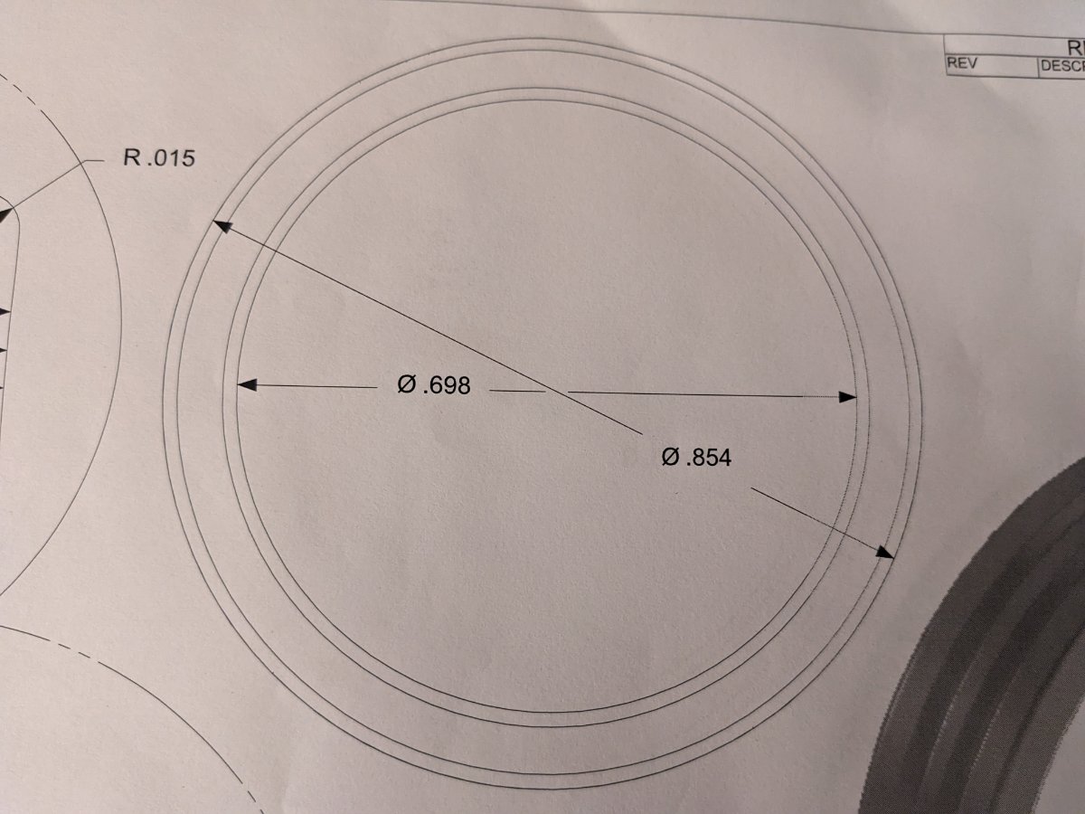
As in photo attached of IronCad drawing environment, I made a ring, and I'm trying dimension between the inside and outside diameter to show the wall thickness, but it's only giving me radius or diameter. I tried shift and other keys to get to measure from circle to circle, but I'm not getting it. What am I missing?

-
Didn't work as I thought it might... Maybe this is what you did... Extend the sheet metal flap too far, and extend a calendar out of the middle of the port past the sheet meta. Then trim the cylinder to the sheet metal part and I can extend the sheet metal flap to the center of the trimmed cylinder.
-
I'll try that. If the cylinder runs past the plane I'm extending then can I use it as the point to extend to? I'll try it
-
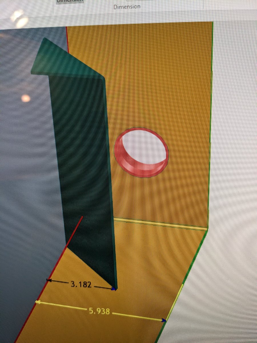
In the photo attached, I'd like to extend the green sheet metal part along it's axis until it hits the centerline of the fitting on the wall behind it. Does that make sense? I tried "to point" and the center of that fitting, but IronCad doesn't understand. Also tried "to midpoint of two points or edge. is there a trick for this? And a related question, I'd also like to know how to rotate the part around one end until the other end hits a certain plane. For instance if you're making a ramp. You start with a horizontal part and raise the other end by a certain vertical distance...

-
Thanks, so helpful! I didn't realize I have to align all three axes together. I was trying to select one and align it, and not finding the option. Also, don't know why I didn't think of aligning each axis to another object which would be aligned to the UCS by default. Thanks again
-
Simple question I hope... If I rotate an object... I used the triball... How can I rotate it back to horizontal... I'm not seeing an option to set the angl relative to the ucs or something.
-
I'm struggling with accurately editing and positioning a cut spin First, I can't reposition the TriBall on the cut spin because it won't select edges like a solid part. I can move the triball, but only arbitrarily, relative to its present location, or relative to edges of other solid part. Is this a bug? If not, how do you make it work? So then editing the profile gets around that sorta, but again, I'm struggling to make dimensions relative to the part that the spin is cutting. it's not snapping to center or outside edge. It seems to only want to be relative to itself, but that doesn't make sense, because it seems to me the cut spin only has value relative to the part its cutting. I'd post video of my attempts, but I can't get the video recorder in Ironcad to work. I click the button, but nothing happens
-
1 is a how do you do it question: I import a STEP file from McMaster of a pipe nipple that I will weld on. However I've either modified the actual part or this is just an available model of one similar enough. So I'd like to shorten it. I'm thinking of two options relative to real world: cut off one end -- most applicable here, or remove some from the middle -- could be useful. Just wondering how you'd do this? To shorten, I can see using the split tool and throw out the part I don't use, or could use any negative shape. But is there a better way? 2. I added some color to differentiate my sheet metal parts, however I inadvertently colored one side of a 3 sided part (a part made of stock with two bends), really I'd like to have the whole part colored as one, but when I select at the whole part level, the one side is overriding the color... make sense? same if I set transparency for one side, then I can't adjust transparency for the whole part as one. So can I remove the smart paint settings? I'm not seeing such an option.
-
Aaaah yes, that makes perfect sense. For the fix, at least. I'm still curious about how and and when those trims lost their independence and became just a part of the sheet metal profile. Thank you so much!
-
Here's the ICS file I repeated the Cut Sheetmetal operation I did previously with the "2in Weld Fitting" and did not get the same result with the Triball. I did notice after clicking around on my previous attempt that the spin which forms the lip on the fitting was nolonger in place, so maybe I miss-clicked somewhere and did something weird. Who knows. I still can't get my 2-1/2" holes in the tank to go away. I tried doing a trim on a test piece of sheet metal and it responded to delete and suppress, and even after I changed the shape of the sheet metal part, so I'm stumped there. There's probably something obvious that I'm not understanding yet that you'll pick up on right away. Lots of learning going on here. hydro_res_5.ics
-
Ah, this is getting interesting * I still can't get these trimmed holes to go away. Not a screen issue: did a "regenerate" and it didn't fix it. Any tips on how to get rid of them at this point? rebuild that sheet metal part? * Found the "cut sheetmetal" tool on the sheet metal tab. Its not exactly like trim because it removes sheet metal where the other part intersects, in this case, removing a ring where the flange went through, whereas trim removes everything inside the outer face of the flange, making a empty hole. I can see where this would be useful. I could use a solid cylinder to make a hole with Cut Sheetmetal, but in this case, I think a Cut Cylinder object would at least save a step. * Oddly after Cut Sheetmetal tool, the Triball on my pipe flange that I just used gets repositioned a little ways away from the flange, seemingly randomly, Thanks for your help and support, I am learning some surf here and definitely appreciate it.
-
Thanks Spencer. So it looks like you deleted the trim from the tree in the scene browser. Except I tried that and despite the trims being gone from the tree, the holes are still there. I had three holes trimmed for three different fittings. I think one that was created more recently did react. Disappear when suppressed or deleted. Maybe I have to look a little more closely. Wuld changing the sheet metal shape effect the trims editability? I wonder if trimming is a good way to do this or if I should have just used a cut cylinder to make the hole? Or something else? Does a trim always remain a property of a part? In this case it makes senses that it would, but if I think of other trim scenarios don't seem like it necessarily would, like of you change the part after the trim, or a split...
-
I'm not at my computer right now so I'll try to explain better. The tank is a rectangule of ⅛" aluminum made with sheet metal tools. Two "c" shapes that fit together. The weld fitting has a lip on it that would sit inside the hole in the tank. So, I position the fitting against the tank with the lip sticking through and used the trim tool to trim the tank part with the fitting as the cutting part, removing the tank material from where the fitting intersects, leaving a hole. At that point it seemed like the trimmed hole was like a part, like a negative cylinder extrusion through the sheet metal would be, that I could later modify. However now I can't seem to do anything with it. I do have three trims in the parts tree for the three holes I made, but deleting or selecting them doesn't seem to do anything. One thing is I did extend the length of the sheet metal part with the trims in it. Would that brake it, or am I missing something? I thought this would be a good idea because the hole has to be correctly sized for the fitting with a minimum of human error. If this doesn't make sense, I'll make a video later. Iron cad can record screen videos now?
-
I think I should be able to delete or otherwise remove a trim... Am I wrong? I used a pipe fitting to trim a hole in a sheet metal tank where it would be attached. Now I'd like to move the fitting or change it's size, but I can't seem to delete the trimmed hole any more. Did something make it permanent? Now how do I get rid of the hole? Should I not have done it that way?
-
Thanks so much. The section tool was what I was looking for. If I'm understanding correctly, I could also show hidden edges and select on them for the measurement? Thanks again and sorry for not responding quicker. Best,
-
This might be a silly question, or an easy answer (hopefully), but how do I measure the inside of a box? I can decrease opacity of one side to see the inside of two opposite sides, but I can't select them through the translucent side. There must be a way to do this. If I hide the one side, it's connected to the two other sides (sheet metal part) so the part I'm trying to measure hides, too. Maybe there's a way to hide just one side of a sheet metal part? Thanks in advance.