RobH2
-
Posts
33 -
Joined
-
Last visited
Content Type
Profiles
Forums
Blogs
Downloads
Articles
Gallery
Everything posted by RobH2
-
@Nickul Thanks for the confirmation. I just wanted to make sure I wasn't missing some setting or tweak. Looks like I'm not. I'll just sit on my hands and be patient. Again, not a major issue at all.
-
Thanks for finding that post. Those are the same issues I'm talking about. Glad I'm not the only one. Looks like Ironcad needs to work with 3DConnexion to implement the newest SDK so the problems can be solved. For those of you who have zoom speed and similar issues, one thing I've found that helps sometimes is to select your object and hit the 'FIT' button on the Spacemouse. That will center and snap the object to the screen and I guess reset some transforms. The Spacemouse will behave a bit better after doing so, but will start misbehaving again. So, I'm used to hitting the 'FIT' button a lot when using Spacemouse in Ironcad. Until Ironcad works with 3DConnexion and updates the SDK it seems like we aren't going to see any fixes.
-
Yes, I have a dead zone. I realize it's difficult to ascertain what I'm describing with text. Next time it happens I'll grab a video. I've moved on for now but as soon as I can I'll upload more info. But basically, if I slowly approach an object, as I get close, instead of going closer the whole view will just abruptly flop around instantaneously. I have to zoom out, find the object and then try to push in again. When I get close again, flip. So what I do is take over and drive with the keyboard and leave the Space Pilot alone. That gets me through. I'll record something next time it happens. It's not a show stopper, just annoying now and again.
-
Does anyone else use a Space Pilot with Ironcad? If so, have you experienced 'Gimbal Lock' issues. If I approach an object, when I get close using the Space Pilot the whole view will just whip around to some angle instantly. I can't get close enough without it snapping away to a random angle. I've used the Space Pilot for years with Max, Maya, Rhino, etc., and don't have this issue. Maybe there is a setting I haven't found or am unaware of. Anyone else found a way to prevent the 'Gimbal Lock' snapping?
-

How to export Caxa Poly to Ironcad for Extrusion
RobH2 replied to RobH2's topic in General Discussion
Thanks Kevin, like you say, I have to start a new sketch in the plane I want. Then it will 'Paste.' I was just trying to paste into the 3d window, like I do in 3ds Max. Thanks for helping me figure out what I should have been able to in the first place...lol... But, maybe this will help someone else. -
How to export Caxa Poly to Ironcad for Extrusion
RobH2 replied to RobH2's topic in General Discussion
Well, I tried that and no go. It was my first intuition. I'll work on that some more. -
I may be thinking about this from the wrong direction coming for primarily a 3ds Max background but a client sent me DXF files, that I've converted and opened in Caxa. I want to grab a few closed splines, copy them to Ironcad and extrude them. I can't find any info about doing that on Google, Youtube or in the nearly 400 page Caxa manual. The Caxa manual has lots of good info but it's not good for finding what you need of you don't know what to look for. For instance, if I search 'Extrude' in Caxa's manual, no hits. I've searched other terms and can't find anyhting pertaining to getting a spline into Ironcad so I can extrude it. There is a lot of info on getting 3d models to drawings, but none on going the other direction. Is it possible?
-
I'm having a similar problem in 2020. My client sent me a DXF which I imported. The text height is fine in his drawing but if I add a dimension, the text height is about 1/10th the size of his. I'd like them to all be the same. The closest menu I can find to the video above is 'Style Manager.' If I look at the 'Properties' panel on the left and see that the 'Dimension Style' is 'Standard' I then open the 'Style Manager' and find 'Standard' under 'Dimstyle.' If I click on 'Standard' and go to the 'Text' tab, I can change the 'Text Height' field under 'Text Appearance.' I hit apply and the dimensions that were on the drawing I imported from the client all change to adapt to that size. But now, if I go to add my own dimensions, my text height is very tiny and unreadable. It does not respect the size change I just made. Apparently there is another place I need to make the global change and I can't find it.
-
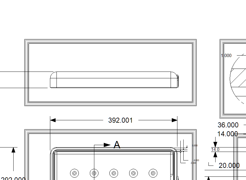
This is helpful in a 3d view. How about in a Drawing? I have a file with a lot of dimensions. I used 'Style Manager' so set two decimal places but I want to round up. I have the dimension 4.105 and I'd like it to round up to 4.11 but it keeps rounding down to 4.10. How can I set it to always round up if the three decimal is 0.005 or higher?
-
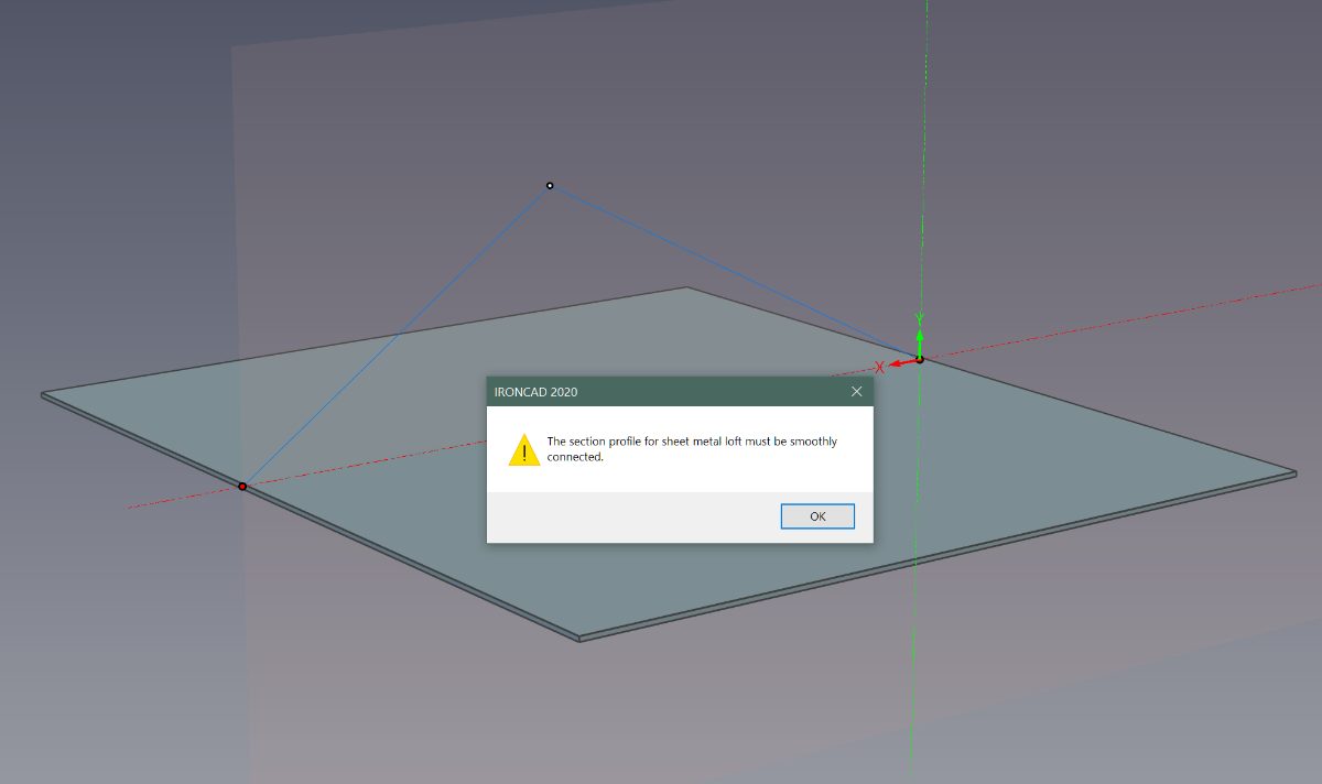
IronKevin, thanks. Looks like our messages crossed. So yea, that's it and the hint is in the word "Smoothly." I took that to mean "no gaps" instead it means what it says, "smoothly." If I now add a minimal 'Fillet' to my points, it works. I hope this simple 'User Error' helps someone else and I appreciate the fast response. Hey, say "hello" to my nephew Cameron Schriner if you guys are in the same office. Thanks Kevin...
-
I think I might have the answer. All points must be smooth and not have any angles. That works for me. But, I followed a tutorial that makes right angles. So, I'm not sure. I hope someone can steer me the right direction.
-
This is the first time I've tried to use 'Curved Stock' in Ironcad 2020. No matter what I draw, it always errors to "The section profile for sheet metal loft must be smoothly connected." I tried using the existing bend line that's automatically there and if I don't touch it and 'Finish' the sketch, no error. But even somehthing as simple as splitting it in the middle and dragging that one point up, the error is generated. And of course, nothing else will work no matter what 'Edit Prodile Location' I choose. What could I be doing wrong?

-
How to 'Turn Off' thick border around drawings?
RobH2 replied to RobH2's topic in General Discussion
Ok, so that's what they are, 'Out of Sync' indicators. Thanks Kevin. Very helpful. Maybe I'll leave them on then to alert me. I'll practice doing some "syncing." -
I can't believe this hasn't been asked but a search came up empty. Drawings put a think border around each view. I've spent two hours searching for settings that control it or a way to turn them off. I can't find it or I'm overlooking it. Can they be turned off permanently?
-
Can CAXA be set to white background and black lines?
RobH2 replied to RobH2's topic in General Discussion
You are the man. Thank you Malcolm. I spent an hour on this and just could not find it. I didn't think of it as a 'Tool', still seems an odd place for it. Thank you.... -
Is it possible to set the Caxa drawing environment to have a white background and black likes, like the standard drawing environment? I can't seem to find any setting to change it globally.
-
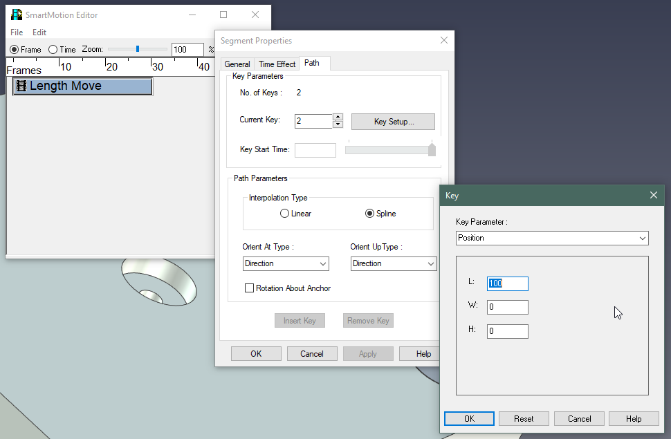
I'm kind of answering my own question. I may have exposed a bug because this is probably not working as intended but it will work if the following steps are taken. If you change the 'Key Parametrer:' in the L, W or H field, and then hit 'OK' the value will revert to the default value of '100. However, if you change the value in a field, say 'L' to '-50', and then hit the 'Enter' key, all of the fields will completely disappear and you'll just see a blank area with nothing in it. You can't see your new value nor any of the other values nor can you now modify any of the fields because they are completely gone. But, if you then hit 'OK' the box will close and if you come back in, you'll see your value and and can now change it again or change the others as you need. This is an inefficient and convoluted workflow for something that should be dead simple, but at least it works. I'm guessing it's a bug as I can't imagine any reason for designing it this way intentionally.
-
From the 'SmartMotion Editor' I right click on a 'Length Move' and select 'Properties...' I hit the 'Path' tab and then set the 'Current Key:' to '2' and click 'Key Setup...' I want to reverse the direction of the motion by inputting a negative value. The default value is 100, I want to use 50. If I type in any number, positive or negative, it won't update. As soon as I click 'OK' it resets to 100. I realize I can just rotate the anchor 180° and get the direction going the way I need but I still can't modify the travel length value. Do I need to do something to unlock these parameters? FYI, none of the values will accept a new number. L, W and H are 100, 0, 0 by default and none of them can be modified.
-
It's easy to see who is learning new software when they keep popping up asking newbie questions, isn't it? But, I am searching hard before I post, I promise. I'm learning 2d drawing. When I use the 'Sketch' tool in an 'icd' document, to say, draw a rectangle, dimensions for length and angle automatically show up as I draw. However, they are really tiny, about 2mm tall and unreadable. If I zoom in, they don't get larger. That's one issue. The other issue is I can't find how to globally change the height of text in dimensions that I place. I have to go in and manually adjust every one separately. So: 1. Is there a parameter somewhere to make the automatic drawing measurements, larger or have them get larger with zooming? 2. Where do I find the parameter to 'globally' set the dimension font size for dimensions I create with the 'Annotate' tools?
-
Hey, IronCAD if you are listening, It would be nice if you modified this tool a bit. I ran the "Convert to Solid" tool on an imported OBJ with 400 parts. It' ran for about 20 minutes. I used a chip clip to hold down my 'enter' key so I could walk away and enable it to keep running without intervention. However, while this works, it has the side effect of completely preventing me from working on anything else on my machine as the 'enter' key is now held down. What about putting a persistent option box in the 'Fit Surface Options' box so that when it comes up you can check, 'Remember my Selection', to allow it to run without needing the 'enter' key? That way it can run for hours in the background and allow the user to make use of that time and use other programs on the machine?
-
Thanks guys, @HDEAR, that was a good 'safety tip' to keep in mind but didn't affect things for this file. @Malcolm Crowe, thanks for making me aware of that separate tool. As 'context sensitive' as many of the tools are, I'm surprised that it does not come up in a right click of an Assembly. Regardless, it's painfully slow and having to hit the 'enter' button each time instead of having it remember my choice is also inefficient (you can't walk away and go get coffee), but... it does work and it solves my immediate need. That's the most important thing, right? Thanks to all...
-
I've imported an OBJ model that has hundreds of parts. It shows up fine in IC and has the red Assembly icon next to each element. I need to do some rough dimensions so I send it to a Drawing. It looks pretty good in the primary views but it won't dimension. None of the dimension tools will recognize geometry and allow me to create dimensions. Also, if I export what I see, the files are blank. I thought that if I converted every element to a 'solid' then things might work. But, I'd have to convert them one at a time. I can't 'bulk' convert to solid. That's impractical for over 400 parts. Am I doing something wrong?
-
Maybe something like what Astute Graphics does for their Adobe Illustrator plugin might be worth investigation. Here is a video of one of the tools called 'Ink Scribe' that is for drawing splines. There are options available much like what IronCAD's sizebox provides. You have options for manipulating what you are creating as you do it, right next to the cursor. What's nice about Ink Scribe is that the input field/option field moves around to keep from covering up what you are doing. It also has a parameter to allow the user to determine how it behaves and how far away it goes to stay out of the way. Some investigation into the merits of this kind of functionality might benefit some reworking of the 'sizebox's' functionality. InkScribeFunctionality.mp4
-
Kevin, thanks. I searched everywhere for something like this. I can't believe I didn't find this. Regardless, thank you. This is exactly what I needed.
-
Is it possible to replace the templates on all drawings? I created a 3d file that has 10 sheet drawings using Bulk Drawings. The template for the drawings was a default one. I now have a proper one with a logo and field parameter customizations and have saved that as a new custom template. Can I now swap out the default templates with the new custom one so I retain all of the manual edits I've made in the 10 sheets?