SHORNBRO
-
Posts
79 -
Joined
-
Last visited
Content Type
Profiles
Forums
Blogs
Downloads
Articles
Gallery
Everything posted by SHORNBRO
-
Problems with PDF Export since Product Update 12-4-2021
SHORNBRO replied to WAENGENEND's topic in General Discussion
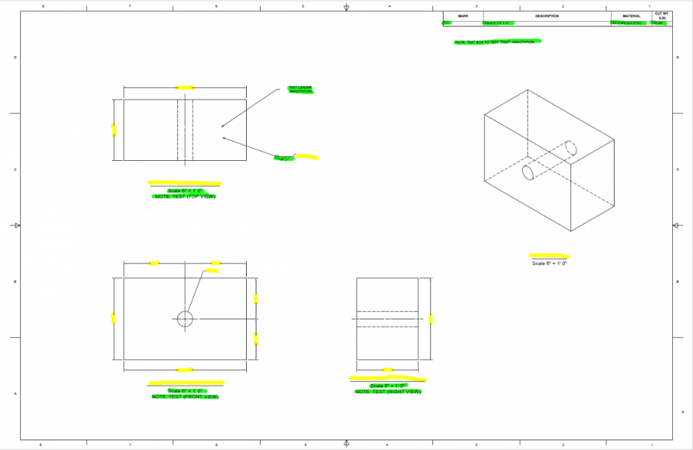
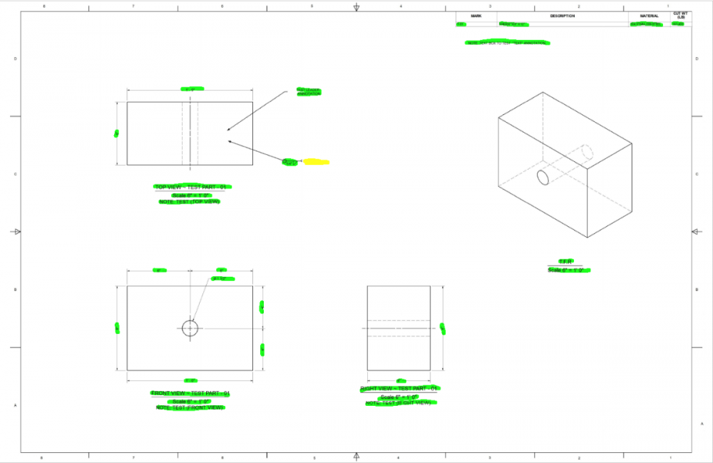
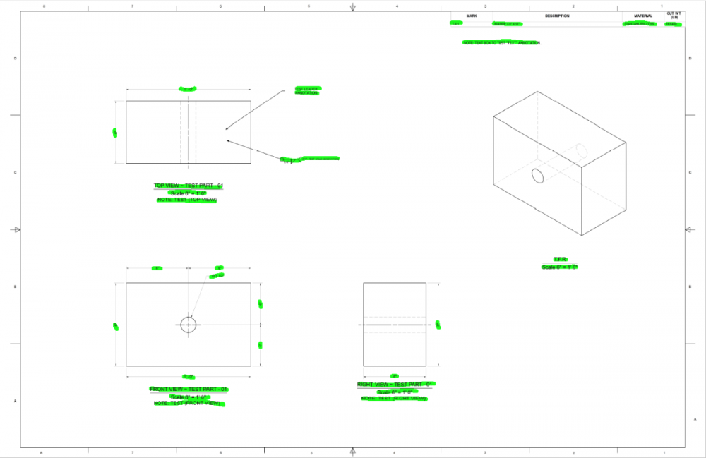
Good morning everyone, To piggy-back off of this a bit as well. I put together a simple test case to help determine what is/isn't working (as I am in the middle of putting together a fairly-extensive detail drawing package for work). I've attached here the parent ICS and ICD files along with 3 PDFs (using 3 different print/export settings). The snips below show snips from ICD & the 3 attached PDFs, highlighting the included and missing annotations. The green highlighter shows the correct/accounted-for annotations. The yellow highlighter indicates where an annotation is missing in the export. ICD Capture (Showing All Annotations): The above snip shows the ICD as desired for export/print. T-01 (EXPORT TO PDF): As others have noted, the above snip shows that the Export to PDF feature does not export dimensions, view names, and other annotations. T-01 (PRINT TO PDF): As you can see above, even with the bog-standard "Microsoft Print to PDF" operation, the weld note annotation does not get printed/exported into the PDF correctly (the weld symbols come in fine, but the note does not). T-01 (NITRO TO PDF): Using Nitro Pro to print to PDF seems to work correctly (although it took two attempts - the first attempt did not correctly print the weld note annotation, the same as "Microsoft Print to PDF"). I hope this helps to narrow-in on a solution, as the export/print to PDF function is integral to getting drawings out the door. Thanks, -Sam TEXT EXPORT TEST.ics TEXT EXPORT TEST.icd T-01 (EXPORT TO PDF).pdf T-01 (PRINT TO PDF).pdf T-01 (NITRO TO PDF).pdf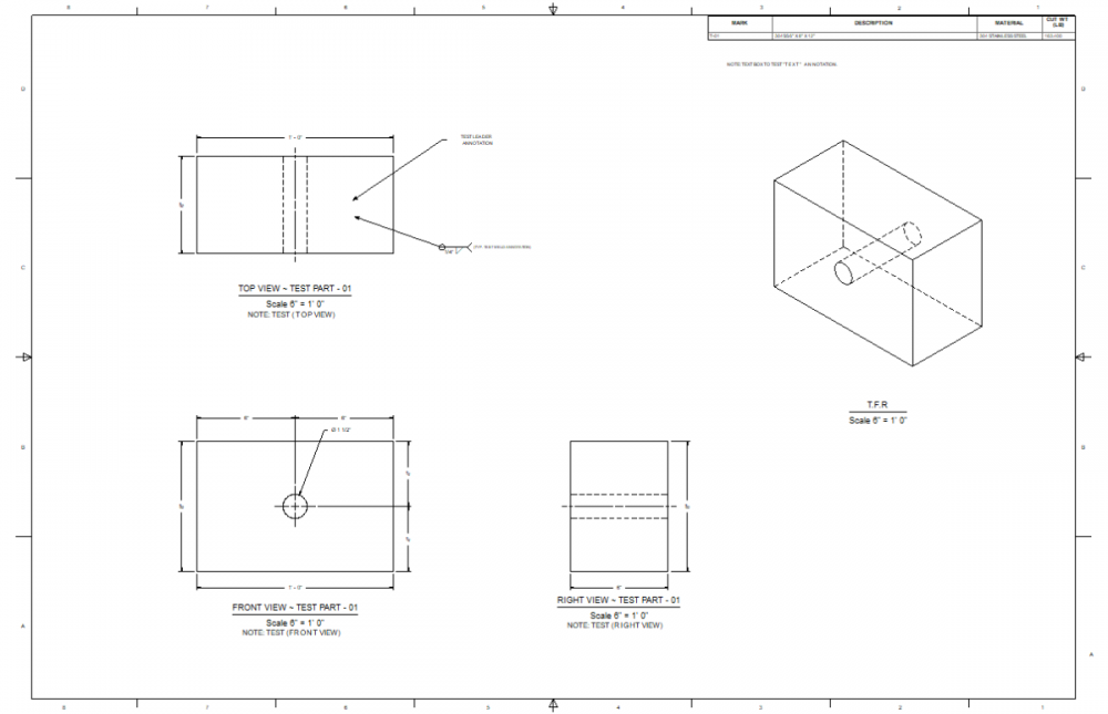
-
Hello everyone, I've run into an odd behavior regarding the View Note in the ICD environment. This issue has been present as far back as I can recall, but I've only had a chance to dig into it further today. When using the "Note" annotation as part of the view annotations, the scaling seems to break when using view scales larger than 1:1. When placing several larger scaled detail views on a recent project, I noticed that when I added the View Note annotation to, the relative spacing between the Note and the View Name & Scale was abnormally large (in my case, I was using a 6:1 view to zoom in on a feature). Looking into it a bit further, I noticed that this spacing becomes even more exaggerated with higher-scaled views. To my knowledge, I have been unable to find a way to reposition the View Note annotation (only stretching the centered width is possible) - this is particularly frustrating when attempting to add a multi-line note. Interestingly, this behavior only seems to occur for the View Note, with the View Name and Scale objects being unaffected. It is also worth noting that this behavior (as far as I can tell) does not seem to have a reverse effect when using less than 1:1 scaled views. Generally, if I have encountered this issue in the past, I forego the View Note annotation and add my own Text annotation and attach it to the view to accomplish the same effect. Has anyone else that uses the ICD environment regularly also run into this problem or found an alternate solution/workaround? In the snip attached above, all of the View Names are aligned to show how the View Note annotation ("Text" by default) is stretched further away with increasing view scales. I have attached the scene, drawing, PDF export, and DWG export as references. Interestingly, the DWG export seems to corroborate that the View Note annotation is treated differently than the View Name & Scale annotations. When exporting 1:1 (rather than selecting the other view-specific scales), the View Note font size scales accordingly with the larger scale views. The View Name & Scale annotations remain the same size across all of the views, in contrast. Could this perhaps be addressed as an Enhancement Request along with the ability to reposition the View Note annotation as well? Cheers, -Sam VIEW NOTE TESTING.DWGVIEW NOTE TESTING.PDFVIEW NOTE TESTING.icdVIEW NOTE TESTING.ics

-
Configuration Management and Externally-Linked Files
SHORNBRO replied to SHORNBRO's topic in General Discussion
Thanks for the tips, Malcolm. To be honest, I think you're right that the functionality I am ideally looking for doesn't exist (or isn't even possible within the current framework). Part of the problem is due to how the assembly organization was handled when these parts were made years and years ago at my company, and part of the problem is due to this being a very niche situation with the flexible rubber parts existing simultaneously as two different states. I'm pretty sure I can come up with a passable workaround until a better solution arises. Thanks for the input. -Sam -
Hello everyone, I've run into another head-scratcher that hopefully someone has run into before. I'm working on building out some 3D models for some existing equipment. I have been making good progress in expanding my company's 3D model library using external links so far. Lately, however, I'm having trouble managing external links and various configurations of parts in an assembly. In the attached scene, there are several nested assemblies containing different configurations of like parts. In the snip below, I have color-coded each line item to match parts/subassemblies that are intended to be linked as the same part, despite having a left-hand or right-hand configuration/orientation. For example, in cyan, we have the "SA-01" subassembly. These subassemblies, although having both a left- and right-handed configuration, are considered the same subassembly in our system all the way through installation. This arises from the "P-02" Rubber Seal part being used in conjunction with the universal bent sheet metal "P-01" Clamp Plate. The "P-02" Rubber Seal conforms to the shape of the "P-01" Clamp Plate. As such, the "SA-01" Assembly for the Seal and Clamp is considered the same subassembly despite being displayed as mirrored in the model. Currently, I can setup my parts/files as follows using external links: P-01 ~ PART - CLAMP PLATE Externally-linked bent sheet metal part Universal orientation (rotate 180 degrees for mirrored assembly) No issues with this part P-02 ~ PART - RUBBER SEAL Externally-linked "sheet metal" rubber part made as sheet metal for fold/unfold & flat pattern for fabrication 3 Configurations Default/Flat Left broken Right broken Can be pulled into the next-level subassemblies (SA-01 & A-01) correctly based on configuration chosen Configurations break at top-level assembly in which the Left & Right configurations are both present I infer that these break because both parts are externally-linked to the same source and are thus internally-linked in the same instance, preventing alternate configurations from being used. P-03 ~ PART - GUARD PLATE Externally-linked shelled solid part (representing a broken sheet metal part) 3 Configurations Default - no holes Left - holes on left end Right - holes on right end Can be pulled into the next-level subassemblies (SA-02 & A-02) correctly based on configuration chosen Configurations break at top-level assembly in which the Left & Right configurations are both present I infer that these break because both parts are externally-linked to the same source and are thus internally-linked in the same instance, preventing alternate configurations from being used. Technically, if I was designing these parts from scratch, they would be 3 distinct parts, going into 3 distinct subassemblies. However, I am currently trying to adapt the models to our pre-existing assembly structures as possible before rocking the boat too much and diving down the rabbit hole of upsetting existing (working) standards. P-04 ~ PART - END PLATE Externally-linked flat plate Universal orientation No issues with this part P-05 ~ PART - BASE PLATE No issues with this part - only one instance in overall assembly, no configurations needed SA-01 ~ ASSEMBLY - SEAL & CLAMP Externally-linked subassembly of parts 2 Configurations Left - using left configuration of P-02 Right - using right configuration of P-02 Unsure if breakdown of configurations in overall assembly occurs at this level or at the next level down SA-02 ~ ASSEMBLY - GUARD & SEAL Externally-linked subassembly of parts 2 Configurations Left - using left configuration of P-03 Right - using right configuration of P-03 Unsure if breakdown of configurations in overall assembly occurs at this level or at the next level down A-01 ~ ASSEMBLY - GUARD & SEAL Externally-linked subassembly for right-side configuration of parts A-02 ~ ASSEMBLY - GUARD & SEAL Externally-linked subassembly for left-side configuration of parts A-00 ~ ASSEMBLY - BASE & GUARDS Combined assembly of previously-noted subassemblies, parts, and fastening hardware At this level, the different configurations needed by linked parts/assemblies seem to be at odds. My apologies for the drawn-out description above - I'm not quite sure how else to describe the situation I'm running into. Generally, if possible, I would like to be able to display these different configurations simultaneously while still utilizing the functionality of externally-linked parts. I think I can piece together a work-around by faking-in unlinked parts to convey the same geometry in the model while losing some of the externally-linked functionality we use for organization and to populate the BoM cleanly. This issue has cropped up a few times and we have come up with workarounds in the past, but it would be nice to figure out a better way to tackle this if possible. Hopefully some of you out there have some ideas. Thanks! -Sam P.S. The ICS file I attached is intentionally not externally-linked to try and simplify things a bit. However, the end goal would be for all parts/subassemblies to be externally-linked as much as possible. CONFIGURATION TEST (UNLINKED).ics

-
If it were me, I would follow Spencer's example. Sketched bends are useful, for sure, but for this situation, it is much faster and simpler to drop your bends as Spencer demonstrates in the video. I was able to correct the model in your scene, though. The main issue was that your sketched bends were interfering with the flat geometry. I added some very small bend relief cutouts to the side "wings" of the model so that the bend can be successful. You can modify these as needed for your design. Hope this helps clarify things a bit. -Sam Bend example - SAM.ics
-
MECH MODE TEST.ics Just as an additional follow-up, I rebuilt the model for my own practice and simplified the constraints a bit as an example for you. Hope it helps! -Sam
-
2021-03-12 09-41-25.mp4 Good morning, I'm not sure if this will help, but I made a simple test model to demonstrate how I would achieve this. I would try the following steps: Build out your model and organize the assemblies as needed. I would setup constraints to lock down each assembly's parts in relation to one another. For the door subassembly, I used a distance constraint in each direction to lock the hinges on the door plate. For the box subassembly, I similarly used distance constraints in each direction to lock the hinges to the box body. Next, constrain the subassemblies to one another. I would use a concentric mate to align the hinges between the door subassembly and the box subassembly. I would use an align (or zero distance) constraint to align and lock the door in the z-axis relative to the box - this is so the door doesn't slide up and away from the hinge pins. From here you can enter Mechanism Mode Navigate to the bottom right of your screen and set the selection box (next to your Configuration selection box) to "Assembly/Part". Now you should be able to grab the door subassembly and swing it around between a fully open and fully closed position. A few notes: The angular constraint you are using is essentially locking the position at that 90° angle. Unfortunately it doesn't constrain within a range of 0°- 90°, but locks the positioning of the parts/assemblies at that angle, preventing you from swinging the door once you get to Mechanism Mode. When setting up your constraints, the concentric constraint is correct, but you also need something to prevent the door assembly from sliding up and away along that concentric axis - hence in my example I used the concentric and align (or zero distance) constraints to pin the door on the box hinges. Hopefully this helps and I wasn't too long-winded. Best of luck! -Sam
-
Scene Template Keeps Opening in READ ONLY Mode
SHORNBRO replied to DraftingNMS's topic in General Discussion
I'm not sure if this will be of much help, but it may be worth a shot. When I was setting up our drawing and scene templates, I copied the default "Template" from the Program Files and saved it to a folder on my desktop (for easy access). I maintained the same folder structure as the original and then copied/saved the new files in their respective drawing or scene folder within that structure. Then back in the IronCAD options menu, I set the template filepath to the "Template" level of my copied structure. Originally I had similar READ ONLY issues when trying to create new templates in the default folders back in 2019, however generating this (at the time) identical folder on my desktop allowed me to bypass those limitations. Doing it this way, I am also able to create new folders underneath the "Scene" or "Drawing" levels to make custom templates separate from all of the default ones. I hope this helps even though it sounds like you generally tried to do the same thing. One thing I found early on in setting up our templates was that IC is sometimes picky about the file structure when trying to navigate to the directories - particularly in the case of scene templates. Best of luck -Sam -
I've run into a bit of a headscratcher with a simple sheet metal part I'm building. I created a brand new sheet metal part from our standard stock catalog item and added two bends to achieve the profile below. As I was working with the part in a greater assembly, I noticed some edge misalignment. My other parts/faces were square, and as I dug deeper, I found that the new stock part corners were not "perfectly" square, or so it seems. In the snip below, you can see that looking orthogonally to the side face does not display as expected. In taking the angle measurement tool, I confirmed that although very minute, the faces were not perpendicular to one another. See video below. 2021-02-26 11-32-03.mp4 Next, I cataloged the part and dropped it back into the scene. Upon measuring this "new" part, the faces became square, as intended. See video below. 2021-02-26 11-34-39.mp4 Further, zooming into the corner on the original part orthogonal to the side face and then panning the camera (with no rotation), the corner faces seem to pivot/change relative angles arbitrarily. We generally keep perspective camera off while modeling parts, but it almost seems as if the part is being displayed with some aspect of the perspective camera working. See video below. 2021-02-26 11-43-12.mp4 Overall, this odd behavior isn't a huge problem, as cataloging and replacing the part seems to fix the part. Also, the measurement precision is bumped up to the maximum in order to demonstrate the issue. All-in-all, once the full assembly is finished this would likely go unnoticed anyways. However, I thought it worth documenting if it may help fix or avoid a future problem. -Sam


-
ICD Drawing View Scale Behavior - Opening 2020 Drawings in 2021
SHORNBRO replied to SHORNBRO's topic in General Discussion
For some reason, it didn't even occur to me to check under Styles and Layers. It seems fairly obvious in hindsight. Thanks! - Sam -
ICD Drawing View Scale Behavior - Opening 2020 Drawings in 2021
SHORNBRO replied to SHORNBRO's topic in General Discussion
Kevin, I have SP1 installed and double-checked again this morning. Everything is up-to-date. - Sam -
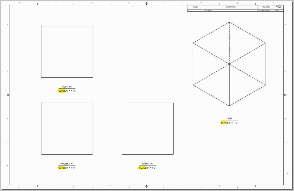
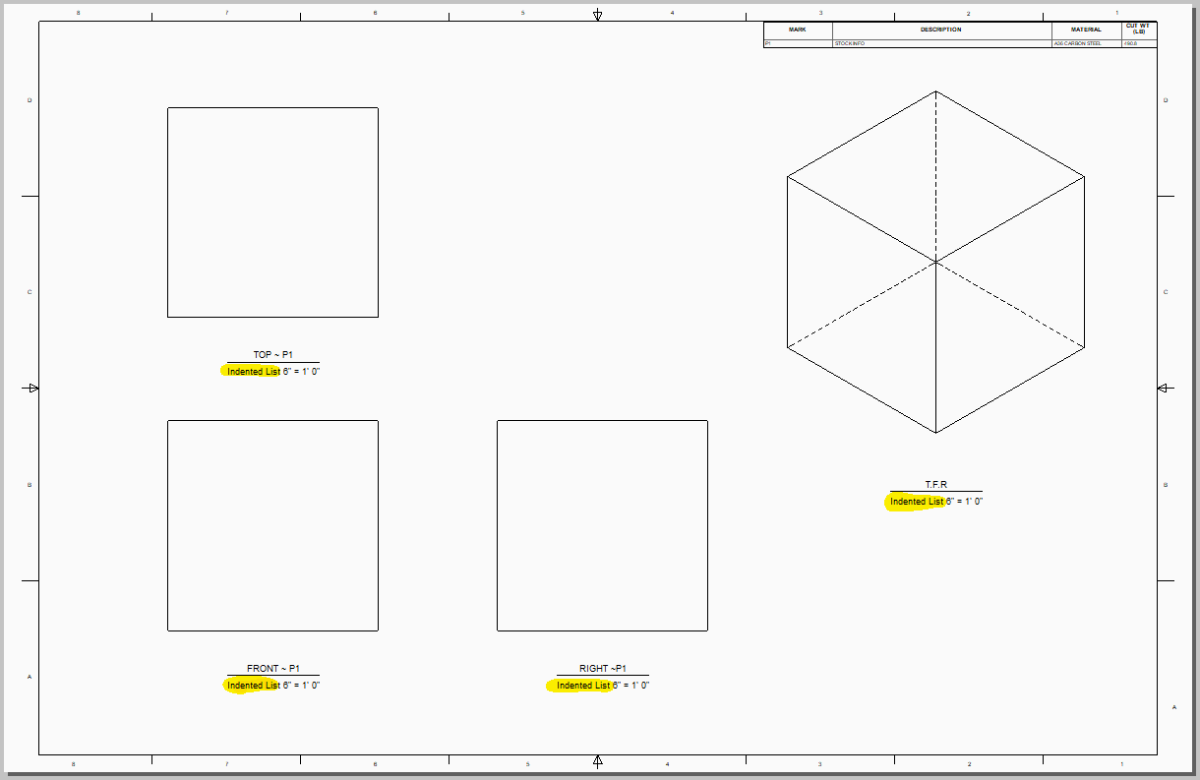
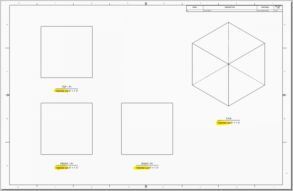
I've run into a strange behavior in which the view scale annotation for drawings made in IC 2020 break upon loading them in IC 2021. By "break", I mean that the text annotation replaces the default "SCALE" is replaced with the string, "Indented List". This behavior is only associated with views that were created in 2020 and then loaded into 2021. New views made in 2021 display the correct "SCALE" text. For newly-made drawings, this is not a problem, however this does create an issue when revising older drawings. View Scales Created in IC 2020: View Scales Loaded into IC 2021: Currently, there are two work-arounds we have come up with which don't solve the problem, but allow us to still finish revisions. 1. Remove the View Scale annotation and manually enter the scale using the View Note annotation. This is not ideal, as it does not automatically adjust the annotation should a view scale be changed. Although not a dealbreaker, our intent with alot of our annotations, BoM information, and Title Blocks is to automate as much as possible with the tools we have. 2. Recreate the Views (and all dimensioning and annotations) when bringing the drawing into IC 2021. Also not a dealbreaker, but unnecessarily duplicating work is a major slowdown and hindrance. I've attached a quick test case I put together. The attached ICS and ICD files were created using the latest IC2020 install. Opening the ICD drawing in IC2021 results in the "Indented List" behavior. I have tested this using externally linked parts/assemblies as well with the same result. For context, this behavior seems to occur on all 2020-made ICD drawings across multiple machines in our office. Has anyone else run into similar issues when updating older ICD Drawings in 2021? Any insight from a fresh pair of eyes is greatly appreciated. Thanks! Best regards, -Sam TEST CASE ~ 2020-2021 VIEW SCALE.zip

-
Hello everyone, I've run across an odd behavior with Auxiliary views in the ICD environment. I'm having trouble with auxiliary view alignment to the parent view breaking upon a view scale change. I've tested several scenarios and the behavior seems to be consistent. Before annotating a drawing, this behavior isn't too much of a problem as long as I layout my views and view scaling correctly. However, once an auxiliary view is fully annotated, it could be a significant setback to have to recreate and re-annotate the entire view unnecessarily. For my test case, I setup a simple broken plate with a flange hole pattern and angled the entire part 45 degrees to setup for an auxiliary view. Initially, everything seems to be aligned correctly. However, upon closer inspection after moving the auxiliary view on top of the parent view, we can see that the entire aux view is displayed with a slight offset (note that the views have already been set to precise quality). *Note:This display misalignment is altogether unnoticeable in most circumstances and isn't particularly a problem, however I thought it was worth noting that there is a slight misalignment prior to any view scale manipulation. Upon modifying the view scale for both views from (1:1) to (1:2), we can see this slight misalignment becomes exaggerated drastically. Furthermore, breaking the view alignment and reattaching to the default alignment seems to over-correct the misalignment in the opposite direction. Overall, this issue doesn't come up very often for me and in most cases it can be avoided. However, there are certain times that I could see this behavior contributing towards setbacks in drawing creation. I hadn't seen this particular issue pop on the forums at all and am curious if anyone has found any useful method to overcome it. I've also attached the example .ICS and .ICD files I used to make the above snippets. Thanks. - Sam AUX VIEW TEST.icd AUX VIEW TEST.ics


-
Hi Craig, Unfortunately, I haven't yet found a viable method for editing imported BREP shapes other than the Move Face command as Kevin suggested. Typically when we import a STEP file to use in a model, we will rebuild the model/relevant features using Intellishapes if we need to edit anything specific. For a recent example, I just brought in a gas spring that we are looking to use with some new equipment. The import model came in as a single BREP shape, however I used that import geometry to then model an editable Intellishape version of the gas spring that can be fully actuated for later use. Although it would be easiest if the import models were fully editable from the get-go, this method works well enough for our purposes. I just see modeling import parts in this way as extra practice. Regards, Sam
-
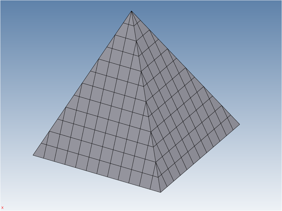
Hi there, So I think I would tackle this from a slightly different angle. Initially, I would determine the overall dimensions of the pyramid when it's finished (for a test case, I made a 12" x 12" x 12" pyramid). Next, I would determine my smallest size building block - in the test case, this was a 1" x 1" x 1" cube to fill the core of the pyramid. The 1" cubes determine the number of layers for the test case - 12. It is also convenient that a square pyramid's symmetry allows us to reduce our work to focusing on one quadrant of the pyramid. (in the snip below, I am showing the layer quadrant reference shape assembly highlighted in yellow). Now that we have our layers and base blocks determined, we need to look at the outside edges and corners of each layer. Using our 1" cube base blocks, we can fill out each layer with the maximum number of base blocks by building to the extents of the top face of each layer. The resulting side and corners necessary to fill out the pyramid show us that we need 2 different side and 2 different corner shapes - 1 type for even-numbered layers, and 1 type for odd-numbered layers. All of this building block layout can be done using sketches or directly build using cross-section projections. At this point we should have 5 different building block shapes: the 1" cube, odd-layer side block, odd-layer corner block, even-layer side block and even-layer corner block. The only remaining steps are to copy these building blocks into place ( I link-copied so that changing one block changes all linked blocks), and then rotate/copy the remaining quadrants. This just outlines the general process I would take to make a pyramid out of individual blocks - to me it is simpler to build from the ground up using fundamental building blocks, rather than try to break an intellishape down into smaller constituent parts. From my understanding, you're looking for more of a top-down method of splitting the overall shape into smaller parts. The method I have outline takes more of a bottom-up approach to achieve the same end result. In my mind, it makes the most sense to roughly create the model in a similar way to how I would want to build the structure in the real world. I've attached the scene I created with the finished 12" x 12" x 12" pyramid broken down. I hope this helps. - Sam PYRAMID TEST.ics