WPONG
-
Posts
235 -
Joined
-
Last visited
Content Type
Profiles
Forums
Blogs
Downloads
Articles
Gallery
Everything posted by WPONG
-
Cary, Kevin, I'm guessing this is a bug. Any comment or guidance here? Is there a settings file or something to send you to prevent / address such a glitch? --Will
-
A bit ago I assigned "M" to the measurement command, a couple things seem to be wonky: 1. Now when I press "M" nothing happens. 2. When I go into the customize ribbon command and press M to assign it (again to "measurement," or any other command, in hopes of IC telling me what it thinks "M" is already assigned to), IC says "Already assigned to " (literally, with nothing following the "Already assigned to") My guess is that the solution is to reset all of my shortcuts, and reassign. (Yes, it's a small trouble -- was just hoping to avoid -- Reassigning would be facilitated by some way to list shortcut keys so I don't have to try and remember all of them, but Kevin mentioned that there is no means of doing this presently). Seems like maybe a corrupted settings file... any other way of addressing this? --Will
-
Perfect. That behaves exactly as I desired. And the shortcut key shows up directly beside "Suppress" in the context menu now. I think this would qualify as a bug, yes? (the selection in the customize menu does not match the option in the context menu?) --Will
-
Okay, I think I figured out why I'm having trouble. I've been using an assigned keyboard shortcut to suppress parts. But the problem is that assigning a keyboard shortcut to "suppress" (which is what I did) actually assigns the keyboard shortcut to the "suppress *parts*" command. I haven't found a way to assign a shortcut key to the true "suppress" command. Here's what I've tried: 1. rt click ribbon > customize keyboard 2. keyboard tab > other > suppress [ assign shortcut key ] OR 2. keyboard tab > tools > suppress [ assign shortcut key ] What results is that the keyboard shortcut key *doesn't* show up beside "suppress" in the rt click context menu, and instead shows up beside "suppress *parts*" in the right click context menu. Is there a way to assign a keyboard shortcut to the true "suppress" command? --Will
-
How to create linked halves of a symmetrical part?
WPONG replied to WPONG's topic in General Discussion
Perfect. Thanks Kevin! I'll be wary of this effect in the future. --Will -
Ahh. Will have a look this evening. Thanks Mike! --Will
-
Some inconsistent behavior that may be on purpose, or may be a bug, but I wanted to understand: 1. I build an assembly something like this Assy1 Subassy5 Subassy6 Part2 Part8 2. Then one by one I suppress Subassy5, Subassy6, Part2, Part8. 3. Finally I suppress Assy1 4. Then I *unsuppress* Assy1 I note that Subassy5 and Subassy6 remain suppressed. But I note that Part2 and Part8 *unsuppress* even though they were individually suppressed prior to the suppression (and unsuppression) of Assy1. This was unexpected. I expected the individual Parts to "remember" their prior suppressed state, just like the Subassy's "remembered" their prior suppression states. Is this a bug, or intended? There may be a rationale for this, but it's definitely not what I expected or convenient. I suppress and unsuppress Assemblies with sub-parts and sub-assemblies (both) within them, and I don't want this action to disrupt the prior suppression state of any sub-parts. Essentially, suppressing and then unsuppressing a parent assembly essentially "resets" (ie un-suppresses) all sub-parts. I hope all that verbiage made sense... (it occurs to me -- perhaps there is a setting for this behavior?) --Will
-
How to create linked halves of a symmetrical part?
WPONG replied to WPONG's topic in General Discussion
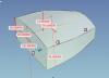
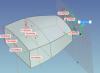
Kevin -- Here is an example that is closer to what I saw before. 1. I've created a part which has 'bosses' around the holes on the bracket. 2. When mirror feature at the end (which I created in the same manner as your example -- preselect all of the features in the tree, then "Mirror Feature" and select the mirror plane), the 'bosses' disappear on the primary half, and instead appear on the mirror-half. I've created the mirror feature, and you can just unsuppress/suppress to see the effect. It's repeatable on my end. Though not identical to what I was seeing before (and which I was unable to reproduce), it is very similar in nature to the problem. In this case, some of the features on the primary-half disappear, and instead appear in the mirror-half. In the former case *all* of the primary-half-features would disappear, and then appear in the mirror-half. Let me know if it behaves similarly for you. Thanks, --Will Mirror_boss_disappears_190424a.ics

-
How to create linked halves of a symmetrical part?
WPONG replied to WPONG's topic in General Discussion
Thanks Kevin - that's exactly what I was hoping to see. Now to some weirdness: 1. I can't seem to recreate the issue that I was encountering last night. Last night, everything looked good until I executed the mirror w/ the checkmark, and then the initial/primary half would disappear and the mirror-half would be created. No kidding. You gotta believe me... I guess I'll just keep a watch out and send you a part if/when it happens again. 2. Today, when I create a mirror, the mirrored half is *almost* correct -- a blend ends up being mirrored about the origin instead of about the mirror-plane. I'll upload the part, and pic. --Will mirror_190422a.ics
-
How to create linked halves of a symmetrical part?
WPONG replied to WPONG's topic in General Discussion
Thanks Cary -- I'll plan to upload a sample this evening. --Will -
How to create linked halves of a symmetrical part?
WPONG replied to WPONG's topic in General Discussion
BSTAFF -- what (I believe) you are recommending is what I essentially did as a workaround. The concession here is that the two halves are no longer linked, and changes to the primary-half (I'll call it) do not manifest in the mirror-half. On a current project, changes can come in waves. Such live-linking is what I am trying to achieve, to avoid the need to re-do the process ("mirror-unlinked > boolean-union") any time the design changes, and also to avoid the associated uncertainty of how current the part is amidst an onslaught of changes ("when did I do that last... drat, I guess I'll just re-do it to make sure before I export to the customer") --Will -
I have a part that I've modeled which (it turns out, as things have evolved) is symmetrical. I've focused my attention on making sure that one half of the part is correct, with the intent of eventually mirroring all of the features on (say) the right side to the left side to make the completed part. My hope was to have the halves be linked, so I could modify the right side and have the left-side update. I've tried a couple things: 1. Use "mirror feature" and select all of the features in the tree. However it seems that the original (right) half-part is 'consumed' by the mirror, so that the right-half disappears, and only the new left half-part remains after I create the mirror. It seems there should be a way to there a way to retain both half-parts when doing a "mirror feature," but I don't see it. Is it possible? 2. Use the triball and mirror the entire part, linked, then boolean. However, when I try to boolean-union the two parts, I see the error that says "The first selected part is linked to one of the other selected parts. These two parts cannot be booleaned together." Workaround is to make the triball-mirror as a 'copy' instead of a link, and then boolean the parts. But this means that the right- and left-halves are no longer linked, and the mirror-copy-then-boolean has to be done whenever the right half is modified. Advice on how to make linked-halves of a symmetrical part? --Will
-
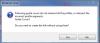
I have a flat plat that I 'trimmed' using a surface (extracted the trimming tool from another part, offset .1mm like a cookie cutter). I have since updated to a new cookie cutter that I want to use that part as the tool for my trim. I've right-clicked on the trim, selected "Edit" and up comes the pictured dialogue. (you'll see a part of the new 'tool' diverging from the old tool in the graphics window as well). The dialogue notes indicate that I should be able to (re) select the trimmed part, and the trimming tool... I don't see how to re-select the trimmed part or the trimming tool... (no selection lists to click, etc, etc). How do I select a new trimming tool? --Will

-
Jolizon -- Exactly what I needed. Didn't realize that I could set the part-level rendering. Thanks much. Cary -- And that's the exact confirmation I was hoping for. I'm fine with a 'coarser' display most of the time, and it's good to hear that the actual part geometry is not affected. --Will
-
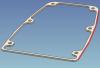
I've generated a 'gasket' by extracting the face of a lofted shape which was smooth and using that face to trim this part. The resulting edge of the gasket looks facted, and i'm guessing it's a display thing, but I'd like to confirm. I suspect there is an obvious setting I just haven't found... Is there a setting in options to reduce any faceting display effects? Model and Pic attached (3 red lines represent the "facets" I'm seeing) --Will Gasket_faceting_190317a.ics
-
Thanks Tom! Helpful to know. --Will
-
Thanks Tom(I think it was?). That did the trick! 'Just not used to having this (nice!) option of switching, and frankly it didn't cross my mind! While I'm learning, have you any advice on which kernels are good for which types of issues? Much appreciated! --Will
-
Thanks Rick. Interesting, when I selected ok, I got another error "Loft cross-section contains invalid curves. Default shape will be used instead." I see tlehnhaeuser's suggestion of kernel switching, and maybe that is why you succeeded (I'll try switching kernels now...) --Will
-
Any thoughts, anyone? (I'm guessing I'm not the first to try and lengthen a loft...) A loft like this is the foundation for a part that I've built, so I'd rather not 'start over.' I'm open to other approaches to achieving my objective too, so I'm please share any suggestions or alternate approaches you may have... Thanks much, --Will
-
Greets all. I'm trying to 'lengthen' a loft by shifting the last x-section sketch with the tri-ball. What I've tried: 1. Select the loft @ the intellishape level 2. Right click the "3" box for the 3rd x-section and "edit cross section" 3. Reorient the view to an isometric-ish view 4. Turn on Triball and drag x-section "3" to lengthen the loft. 5. Click "finish shape" ...and I get the pictured error Attached is the model, and a pic or two to explain. I'd appreciate advice on how to accomplish what I'm after... Along the way, I'd appreciate some clarification on the definitions / distinctions between "Guide Curve" "Center Line" "Profile Locator Curve" Thanks! --Will loft_lengthen.ics
-
Thanks All. I'll give it a try! --Will
-
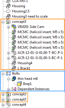
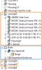
Greets -- Another assembly management question (reference the screenshot attached): I would like to add "Bolts" to the assembly "concept3" and I'm struggling to do so. Background: 1. I have a scene in which I have created an assembly "concept3." (top gold box) 2. (in case it matters: I've made 2 more linked instances of this assembly). (bottom gold box) 3. I've also created a pattern of bolts called (you guessed it) "Bolts." (blue box) I can't seem to figure out how to add "Bolts" to my assembly "concept3". I've tried dragging "Bolts" to a place just below the "concept3" text (ie, just above the "VIM201 Side Cam" text), and other places... Ideas, or something I'm missing? Thanks. --Will
-
Ok. Will give that a go. Thanks Cary. --Will
-
I've been creating some enclosures as structured parts, and so have been doing some "split"-ing. STEP has been the preferred file format for exchange with my customer. So when splitting a structured part, multiple "bodies" proliferate. 1. The original body 2. The splitting body 3. The two 'splitted' bodies Bodies can be hidden, but not suppressed, so when I go to STEP out the files, the result includes the splitting body, and the original body... And since body-renaming is not possible (as far as I am aware -- tried, but was unable, saw a thread on this but didn't see functionality was added), this can add to confusion for my customer. Is it possible to control what is STEP-ed out by what is *hidden* or not? This is common functionality in other packages, so perhaps this is a doable thing in IronCAD? --Will
-
More on this point -- I realize my workflow often involves sectioning precisely because I want to measure and spin about a tight-clearance in a specific area. And when measuring "minimum" with IronCAD, spinning is necessary to see which measurement axis is which (on the little 3-axis rosette that appears with orthogonal measurements). I was just in such a situation. Took the exact measurement I needed, tried to spin, and... bummer, the area spun off my screen because I wasn't centered just-right... Can spinning-with-sections be improved, to account for the actual section-surface being viewed? --Will