WPONG
-
Posts
235 -
Joined
-
Last visited
Content Type
Profiles
Forums
Blogs
Downloads
Articles
Gallery
Everything posted by WPONG
-
I wonder... perhaps related topic (and worthy of another thread, I think) I recently transferred over my keyboard shortcuts/hotkeys using the method you've mentioned (copied over my v24 customization .xml files into my v25 customization folder and then search-and-replaced the version-number-in-2-places"). However, I have *not* yet back-updated the v24 .xml files with all of the new text in the v25 .xml files.. It was not obvious to me how to do this easily, since (as far as the "meld" diff utility could tell, anyway) .xml files are all a single line and therefore not easily diff'd and updated... Not sure if that babble was intelligible... bottom line is that I'm running with my v25 IronCAD with my v24 customization files. --Will
-
Thanks Kevin - I've attached here. Part1.ics
-
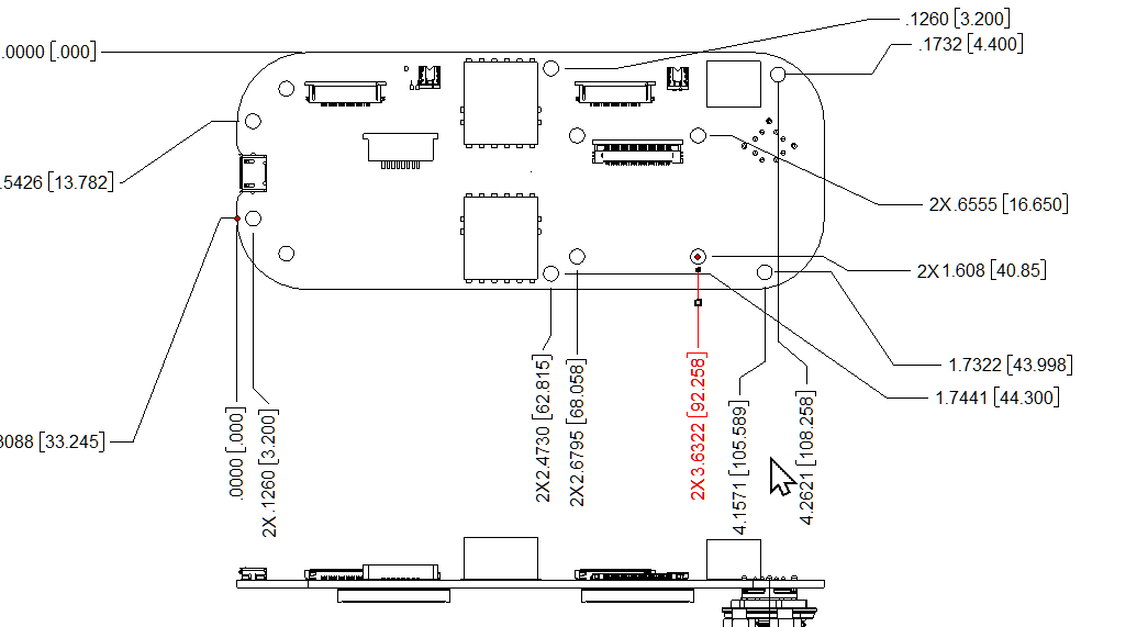
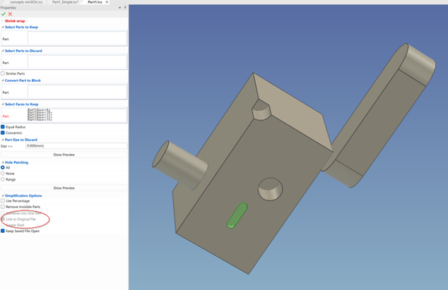
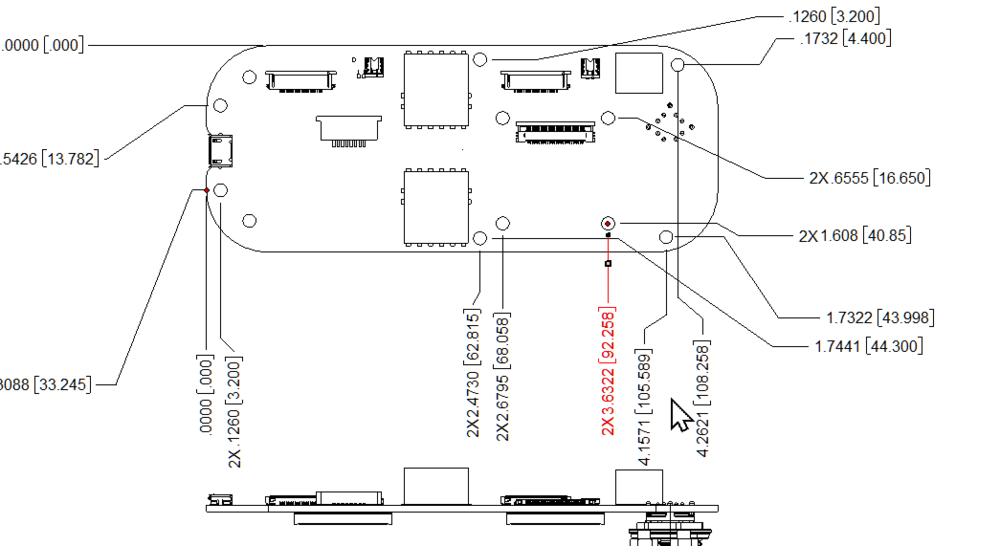
I've watched the IronCAD Academ video on shrinkwrap, and I'm testing options for my needs. (IC2023) For some reason some of the options are greyed out (“combine into one part,” and “create shell”). is there something I need to do differently to enable those features? (ref: The scene below has 3 individual parts, one of them a step file (the positive slot); note the greyed out features). I work a lot with step files of PCB's from our electrical team and design parts that must variously clear or interact with the pcb's at the component level. this is whence my interest in shrink wrap -- interacting with the large step files can be slow/burdensome. So a couple sub-questions come from this 3a. When i save scenes involving the PCB's, I notice that there is a *lot* of "regenerating" and "faceting" that goes on (minutes-worth, go-get-coffee-worth), and I believe it is associated with the PCB's, even if they are suppressed. Is this inevitable, or is there a way to avoid such regens / faceting? Maybe obvious? I haven't played too much with settings yet, and I'm hoping someone else might save me a lot of tinkering (even if with the sad news that there is no way around this). 3b. I'd welcome any recommendations for efficiently shrink-wrapping or simplifying PCB's. Often, my interest is to obtain an "external-envelope" (not just a convex hull, but a behavior akin to actual shrink-wrap, which follows down into the nooks and crannies between parts) --Will
-
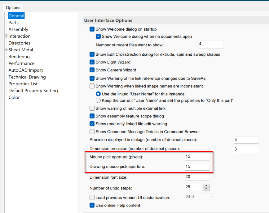
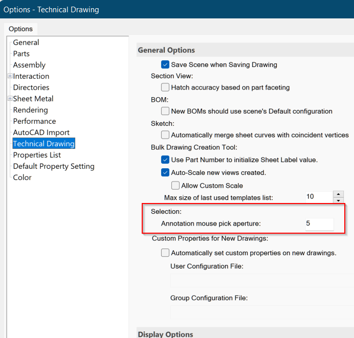
Any wisdom on the various mouse aperture settings?
-
Multiple Links with Triball center -- double-duplicates?
WPONG replied to WPONG's topic in General Discussion
Thanks Kevin -- will try to capture a scenario when it occurs and post. -
Often (in IC2022 it seems more prevalent), when I ctrl-select a few parts and want to make links of said parts with Triball center (i.e. linked duplicates), after I position the triball center and enter "p" then "return" nothing happens until I enter "return" again, at which point I get *two* linked dupes of everything. I then have to go back and delete the extra linked dupes. Is this a known issue, perhaps associated with a setting? It has happened on IC2019 (HP laptop workstation), and is now happenning frequently with IC2022 (HP Envy). It *may* correlate with larger assemblies when my system seems slower (and IC2022 does seem more sluggish than 2019 in general) --Will
-
1. Re. arc dims: thanks. Good to hear 2. Re. picking: 2a. This may have improved with a PC reboot and restart of IC. (perhaps a restart of IC is necesssary for the mouse-aperture changes to take effect?) 2b. There are two dialogues that seem to pertain to drawing mouse aperture. Can you line me out on which does what? pic's attached.
-
"Unable to find image file" -- remove spurious / phantom image
WPONG replied to WPONG's topic in General Discussion
Can this be an enhancement request? -
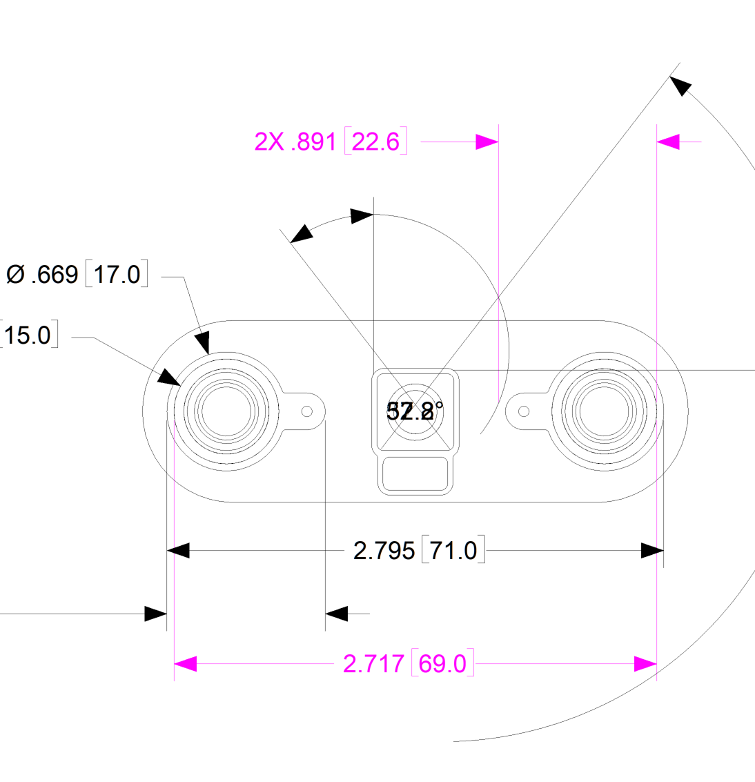
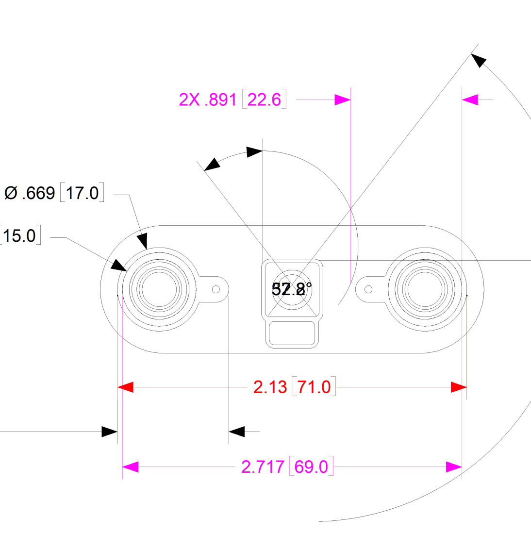
Finally doing some drawings in 2022. a couple issues. 1. Circular feature dimensions not updating: I've seen this a few times now, (hammering, don't have time to recreate and isolate too much but hopefully the below is substantial). when i create a new dimension for two circular features doing the following 1. Shift-click (circular feature) 2. Shift-click (2nd circular feature) 3. Finish the dimension 4. Edit properties of the dimension, change to Maximum / Maximum to get the dimension from outside tangent to outside tangent ... Then the value displayed is still the old center-to-center dimension, 5. Edit properties of the dimension, change precision ... *Then* the dimension updates to the correct value I've attached a couple screenshots. (sorry they are mess -- it's been a re-attachement-fest with a modified part where linear dimensions have turned into angular, etc). One is right #4 (red dim "2.13"), then one is right after #5 (black dim "2.795"). Very unnerving. makes me wonder if other dimensions are actually updating... 2. Difficulty picking features for dimensions This is more qualitative and some things have changed (now I'm on a larger monitor): however It seems more difficult to pick features for dimensioning. some of what I've been doing a. Trying to pick breakpoints on circular features (not sure of the official term, but places where circular features are actually broken into 2 semi-circles) -- the 'point' is very difficult to find -- I've been tweaking the annotation attachment window (default was 3). I sometimes have to hold my cursor off to the side of the desired feature to get the point to light up... b. Trying to pick silhouette edges (niggling voice says that there is a setting for this, and maybe in my upgrade I've lost that -- feel free to remind / guide me here) Thanks again, --Will


-
"Unable to find image file" -- remove spurious / phantom image
WPONG replied to WPONG's topic in General Discussion
Been looking. haven't found it yet. is there a way to diagnose what part or asseembly or sketch was the origin of the problem? -
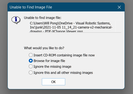
I receive the attached alert when I open a particular scene. I seem to have a persistent reference to a scratch image file in my 'junk' directory (no longer exists). Likely the reference was generated when I was creating a logo sketch from a dxf file in a 2d sketch, but I'm not 100% sure. I've poked around my sketches and didn't see any references, but likely I'm just not looking in the right place(s). Please advise of how I can find and delete this reference within my part? Thanks as always. --Will
-
Okay -- all of the updates Cary mentioned are installed (did do the pu1 update first, then the other previously mentioned updates installed fine) First attempt at a TEAMs meeting worked! It looks like my issue is solved! (the test meeting wasn't entirely realistic, so will do add'l testing) Will report back if problems discovered. Thanks! --Will
-
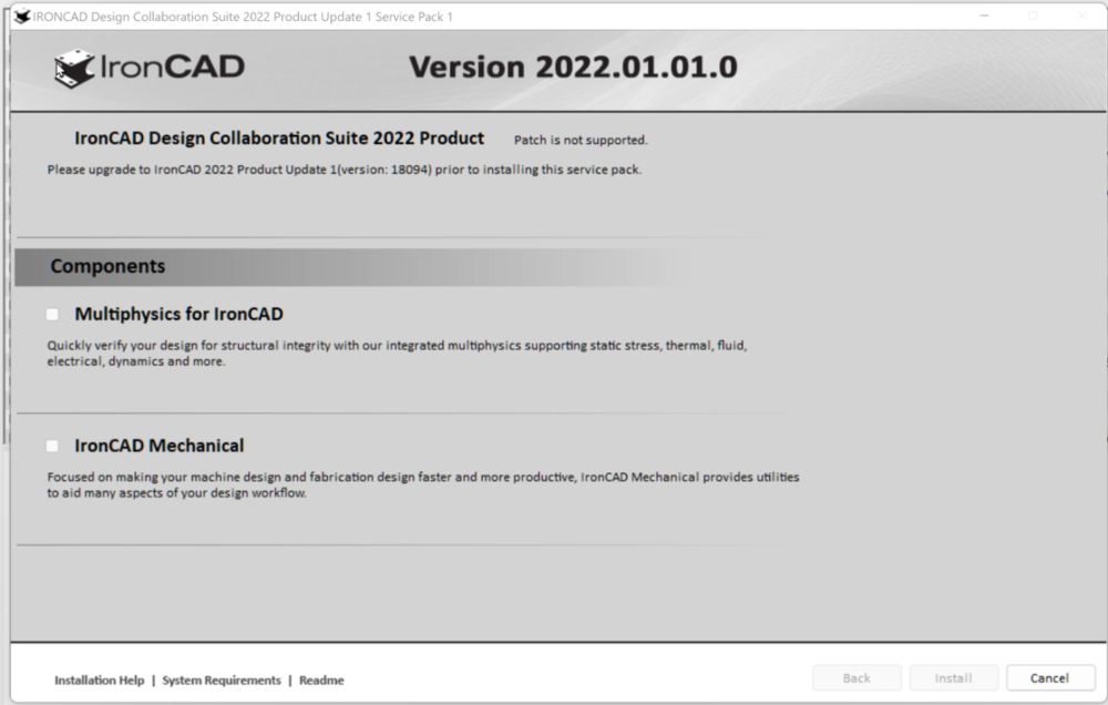
Thanks Cary -- I just tried the first link and got a "Patch is not supported"
-
So to confirm, my statements #1 and #2 are correct, yes? (sorry to be so pedantic -- been burned with software updates in other contexts before)
-
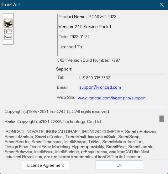
Will do. 1. The date on my "about" (1/27/2022). I surmise that I need to apply all subsequent hotfixes, beginning with HF#1, in sequential order. Please confirm. 2. I would assume (yes I know what that spells, hence my question =]) that IC will know what hotfixes I may already have and will smoothly adapt (the reason I ask is that I actually renewed and installed late this year, and I'm not sure if what I received already rolled-up any of these updates) Thanks, --Will
-
Thanks all. FYI, I'm on windows11. Not sure if I have the hotfix (would it display on the "about"?. Here's a screenshot. And just so I don't botch something if I still lack the hotfix, please line me out on the cleanest way to install... Thanks again.
-
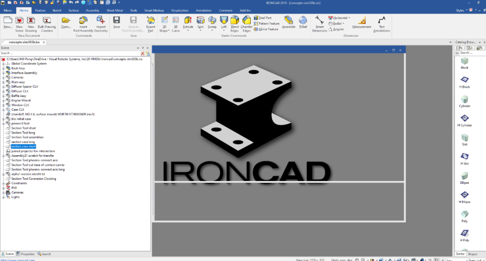
Bump on this thread. I've now upgraded to IC2022, and I've tried all the suggestions above I'm having the same issues as indicated above. Anytime I have an MS Teams video call, I can't run IronCAD -- it freezes with a display like pictured above. I'm able to click items in the browser, but the actual 3d display remains frozen as shown. This is a major issue for me as I'm unable to collab with clients. I've been working around this by screenshots taken before the meeting (if I have the presence of mind) and lots of hand-waving. What is more, the issue is 'permanent' for my session -- whenever I have a Teams meeting, IC exhibits this behavior until I reboot my entire machine to address the issue. (restarting IC doesn't help). Any and all guidance is sought! Thanks. --Will
-
Embarrassing. Found what I need. (need... more sleep) For #2: Annotation > Hatch works most of the time For #3: Still not clear of best approach -- any advice welcome, particularly when it comes to using existing lines of the view to define the boundary. Would be helpful to be able to project edges as in part sketch mode (perhaps there is a method?).
-
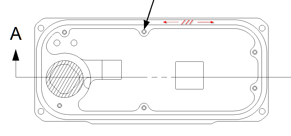
I have a drawing that I need to cross-hatch in arbitrary regions for different reasons. What is the best way to achieve this? See screenshot below (ignore black arrow). 1. Circular region: I drew a circle, then hatched it (left of the screenshot) 2. The 'racetrack' region I've cartooned. I'd like to x-hatch the entire region indicated with red arrows. 3. Arbitrary regions (that may be more free-form, albeit defined with 2d dimensions). Trying to learn the best approaches here. Thanks, --Will

-
I have projected the outline of one part onto the flat surface of another part (this represents a clamp-up/contact region will be treated as a keepout). I wasn't able to pick the 3d curve for dimensioning purposes in my drawinng My workaround was to generate a *2d* sketch and project the 3d curve. Is this the best approach, or any other recommendations?
-
A strange one -- I've been having troubles with my IC display upon startup. If I start IC, then open an assembly (simple or complex), the display won't finish refreshing. This *may* correlate with having been upgraded to windows 11 (unwittingly, grrr), but I'm not sure. It also does seem that if I have a Microsoft Teams meeting running prior to running IronCAD, the problem occurs more often. Here's what my display looks like when this problem happens. The scene has successfully loaded, but the display is 'stuck.' I'm used to seeing this briefly as a scene is loading, but in this case it persists, and no amount of "regenerate display" will help -- I'm unable to ever see my scene. I *thought* killing Microsoft Teams would help, but that is inconsistent. I usually end up having to reboot to solve the problem. Thoughts? Thanks much.
-
I'm having a bear of a time updating drawings. (I haven't experimented fully on this trying different scenarios -- don't have time at the moment). I have a drawing with ordinate dimensions, and when I try to move or edit properties for specific dimensions, it's very difficult to successfully pick them -- very often the dimension under my cursor will *not* highlight, and I accidentally pick and move the wrong dimension, quite a distance away! Typical situation below. Note that the dimension far away from my visible cursor is highlighted. This *may* correlate with how zoomed in I am, but again I haven't had time to test as I'm under the gun presently. Is this a known issue or is there a settings fix, or patch? *Really* frustrating and lots of time lost. I end up having to hover all around the dimension of interest and then have to iteratively click to try and get the intended dimension. I'm running 2019. Thanks much, --Will
-
Got it, so .stp files are the issue. Step file fit-check was one of the main reasons I wanted to roll this out to a colleague, so he could review my native IC files and pull in vendor-supplied .stp files (lingua franca for electronic discretes) and boards he's designed (output from KiCAD). I see the trans can be purchased at resellers. Will weigh. Thanks.
-
Ahh... I actually have a regular IronCAD session running at the same time -- I wanted to import into ICCompose to see how things worked. So I have *both* running... What I did in IC Compose was try to open a .stp file.
-
FYI, I'm running IC off of a Dongle. I wonder if this is a factor...