


WPONG
-
Posts
235 -
Joined
-
Last visited
Content Type
Profiles
Forums
Blogs
Downloads
Articles
Gallery
Everything posted by WPONG
-
Very helpful / educational Cary. And the more I work in Ironcad, the more I see the uniqueness of the innovative part paradigm. I'll play with this. Thanks again (and for the rapid answer, very helpful as I'm in the throes of a design real-time, under a bit of a crunch). --Will
-
Feeling silly -- this has to be obvious I have a structured part. I've created a block, dragged an hcylinder onto the block. I simply want to tilt the hcylinder so that it's no longer perpendicular to the surface I dropped it on (for example, I'd like the hole to come in at 20deg from perpendicular) I've tried rotating the hcylinder with the triball. Works fine in an innovative part. I can't seem to make this happen in a stuctured part. It keeps snapping back to perpendicular. I suspect this has to do with anchor behavior? I've messed with intellishape properties, but haven't found the right setting yet... advice? --Will
-
Thanks for this -- it's a bit challenging to see but I will review and post again if add'l clarification would be helpful. --Will
-
I'm have a machined part from which I've extracted these surfaces: And ultimately, I would like to have a continuous surface that looks like this: What I have done is outlined below (after different iterations of things that also didn't work, so this may seem a bit indirect as a result) 1. Extracted the indicated surfaces (Part 937 in attached scene) 2. Extended the boss surfaces up till they are level with the other ("wall") surfaces. ... tried to "trim" the wall surfaces with the "boss" surfaces... "this operation cannot be performed with trimmed surfaces" 3. Generated intersection curves where the (extended) boss surfaces intersect the wall surfaces (Part31 in the attached scene) 4. Executed a "trim": 4a. selected the wall surfaces as the part-to-trim 4b. selected Part31 as the "element" for trimming 4c. did not merge surfaces as part of the trim (this failed before, so I figured I'd merge somehow afterward) 5. Tried to merge surfaces (I get the "this operation cannot be performed on trimmed surfaces") A couple questions come from this. 6. I *think* my steps 1-4 above resulted in a series of separate surfaces that are not merged -- Is this the case? (However, I just did a quick test and it appears that I can use the part as a trimming tool for another body) 7. Along these lines, from previous (helpful) conversations here, I believe that Ironcad sometimes treats "close" surfaces as if the are a single entity already(?). 7a. If so... are they sort of already "merged"? So when is "merging" actually needed, and 7b. If so... how does one "merge" surfaces that have been trimmed to fit one another? Apologies for the deep dive. I'm just wanting to align my thinking with IronCAD as far as handling of surfaces. Any guidance would be greatly appreciated. --Will Part937.ics


-
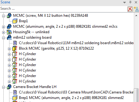
I'm unclear on the icon-types in the scene browser. I'm guessing there is a 'key' somewhere (please advise. I did a help search on browser , icon types, etc -- apologies again if I missed). Specifically, I saved a part as external, and noted the absence of the familiar chain-link modifier, and instead saw a teal-ish square modifier... then I noted that the teal-ish modifier showed up on other part icons as well that weren't external links. Can someone spool me up (or again direct me to appropriate resource) for the different modifier meanings? Here's a pic of my browser, and thoughts on the icons 1. The teal-ish box @ bottom left of icon -- appears on both a unmodified Brep import (part #1) and a external part modified Brep (part #4) 2. The unmodified icon -- this is a local modified Brep import part as well 3. The teal-ish arrow @ bottom left of icon -- this is a nonlinked part 4. The chainl-link icon @ bottom right of icon -- this means externally linked file, I think(thought) Thoughts or a reference key would be greatly appreciated. Thanks much --Will
-
Thanks -- Sorry about the redundant post (forgetful of what I've posted along the way, and I don't think I can see bug reports anymore...)
-
1. I assigned a shortcut key "K" to suppress shapes [rtclk menu bar] > Customize toolbars/menu/keyboard > keyboard tab > Others > "suppress shapes" 2. Then I (accidentally) tried to assign the same key "K" to "unsuppress" ... > Others > "Unsuppress" 3. The text below the dialogue then says "Already assigned to Corners." I would have expected it to say "Already asssigned to "Suppress Shapes"" --Will
-
As of yesterday, *all* of my shortcut keys are now gone. I can't recall if this was discussed (did a search, but might be missing) Is there a shortcut key file that is stored anywhere for access and modification? (any chance windows update has anything to do with this? there has been a wave of updates recently). Definitely annoying. My shortcuts are instinctive enough that I don't know which ones were custom and which were native. I only discover them slowly as things don't work as expected. It would sure be nice if there were an editable repository for them that one can store a backup of, edit, evolve, etc. (again, maybe this exists already. If not, enhancement request please?) --Will
-
Manually hide selected lines in Ironcad drawing?
WPONG replied to WPONG's topic in General Discussion
Thanks Kevin. It worked like a charm. -
I have a drawing in which I'd like to hide selected lines manually (strictly, they are visible in the view, but for clarity, I'd like to hide or erase them). What is the best way to do this? Thanks, --Will
-
I have a mass mounted to an angle bracket, and want to investigate modal performance of the bracket as I modify the design. Baseline is pictured here. 1. Model setup and performance look good w/ prelim inspection: I've assigned Aluminum material to the angle bracket and Cast Iron to the mass (the block on top); I've 'glued' the parts together, constrained a 4-bolt pattern on the bracket upright. 2. However, I'm trying to make sense of the Node Inquiry plot -- It is not sinusoidal or even cyclic. As I've tried to understand, other questions would be helpful to answer. I may be I'm lacking some baseline understanding (apologies if so): 2a. How do I determine the time-span of the plot in seconds? 2b. Along these lines: Is it possible to see the "time step" size? (I see that the step size control under "Advanced Opt." is "automatic" by default) 2c. Output displacements are indicated in "mm" the contour-plot and the Inquiry Plot. What is the assumed corresponding input displacement magnitude? (I'm thinking in terms of transfer-function). Thanks, --Will

-
Cary -- helpful video, thank you. A couple questions ... 1. Technique equivalence: That was a helpful technique for extracting surfaces shown, got it. For my education, are "a" and "b" essentially equivalent, or are there differences I ought to be aware of ("b" is what I had done before) a. [shift-select surfaces] > rt clk > create > extract surface b. surface tab > extract surface > [select surfaces, populating the dialogue] 2. Free edges: To closeout the hopper, ruled surfaces were strung between two opposing edges of the hopper, and I note that it was not necessary to stitch the other two free edges explicitly into the rim of the to the hopper. In other CAD software, this must be explicitly done, or those free edges would prevent solidifying. I gather that the kernels (I should have tried this -- still not used to having that option) handle free edges differently? 3. "Sew" vs "Merge" (vs "stitch"). Please help me understand the differences here / when to use them vs the other? Also, the term "stitch" shows up in the dialogues (even in the video example), which I'm trying to harmonize with the other two. I guess I'm trying to spool up on IronCAD's perspective re. surfaces (vs Catia, for instance). Surfaces, quilts, stitch, free edges, etc, etc. Maybe a brief summary of surface-related terms, and how IronCAD views combined surfaces, free edges, etc? Open ended question, I know, but I think the background would help me become more proficient at use of the module... --Will
-
Malcom -- thanks for the post, I'll have a look (spending a good portion of my time away from the computer these days -- so it goes overseeing design, fab, vendor relationships, etc -- you know the gig) I am seeing this when I try to view your videos, however:

-
Thanks Cary and Blake. --Will
-
It looks like I have exceeded my "attachment quota," (" You have used 7.06 MB of your 500 kB attachment limit. ") due to past posts since before the forum updates. Obviously this is a problem, as I would like to post files for review on occasion, and it is likely that accumulated postings will exceed 500kb pretty quickly ... Is this the way things will be? (Perhaps I'm the only one?) --Will
-
I have modeled solid which contains a pocket. I'd like to create a negative of the pocket. Think of it as a "casting" formed by the pocket. My plan has been to 1. Extract surfaces of the pocket (surface > extract surface > [selected surfaces one by one]) → Done 2. Join the surfaces together into a single surface → having troubles here 3. Cap off the end of the extracted surfaces 4. Offset the surfaces by .010" inward (I prefer this to "scaling" since I desire an actual .010" offset from all surfaces, and scaling would generate proportional offsets instead) 5. Create a solid from the volume that is formed. This workflow comes from an approach that is suited to other tools (namely Catia). I'm struggling to make this happen, probably due to lack of experience with IronCAD surfaces. I'm guessing there is another approach suited to IronCAD. Thoughts on how I might go about this? I will attach the file....Ugh. Looks like I can't attach a file due to space limits on the system? Perhaps suggestions on the general approach? --Will
-
Probably an obvious fix to this, but as I was composing a reply to a post, some "suggestions" came up, and wouldn't disappear. I had to add extra lines in my note so I could see what I was typing, then deleted the lines and submitted my post. Escape didn't work, right clicking the box didn't seem to yield options to remove the box... how to make these popups disappear? --Will

-
Nick -- Very cool! As you say, it's different from what I was looking for, but can be very helpful, and perhaps serve a similar purpose. I do note that your section lines were white in the example, and appear more 'foreground' than my test yielded. I tried to edit properties, etc. Are there some tweaks you did to get such good visibility of your section? --Will
-
Thanks Malcom. --Will
-
> q7. Not that I am aware of. We move the existing file to a temporary folder where the assembly in > question can't find it when opening. Then when the assembly asks where the location is, we direct it > to the file we want (such as previous version in superseded folder). When this new link is created, > we then move the original file back so that the links remain to other assemblies. Another great tip. Thank you. > When parts and assemblies are saved externally, the new files created share the same scene origin > as the original assembly from which they came. This can be an advantage if you are inserting back > into the same assembly as it will locate in the same place without reposition needed; but apart from > the original assembly it isn't helpful. So we always move parts to the origin of their individual > scenes, before creating any 2D drawings from them. Got it. Then another question -- if you need to revert or 'replace' a rev-marked version back into the master scene (by means of temporarily hiding the non-rev-marked link file, as you mention above), then is there a technique you use to get the part into the correct position? (since the part is now centered on its own origin...)? --Will
-
Thanks Malcom -- Comprehensive, and helpful. I'm digesting... To avoid confusion with your helpful numbering, I'll distinguish my questions / commenets by prefixing items with "q" Questions / comments: (please do correct / adjust my understanding): q1 For my understanding the "###1" "###2" was just to keep files appearing in the desired order for our discussion purposes, is that correct? q2. So with your workflow, once your initial design is complete (single model environment), you begin externally linking each part and subassembly, and creating separate drawings for each external link. q3. Having saved-external, at this point your 'main' scene is a smaller file, with mostly externally linked scenes of individual parts. q4. Then you can continue to work within your main scene, modify parts at-will, leaving the link names untouched. q5. When publishing drawings or files for review, quote, production, etc, you manually drag a copy of the part(or subassy) .ics file into your superseded folder and manually rename it with the appropriate version stamp. Likewise, you manually drag a copy of the associated drawing into the superseded folder, then manually rename with the revision stamp. q6. At this point, your version-named drawing doesn't know about the version-named, scene, so if/when you need to relink, you simply re-open the version-named drawing and "edit links" to connect it with the version-named scene. q7. You mention re-directing an assembly to link to a different external file. Is there a way to replace / change the external path associated with a part in the browser, or must this be done by doing a Menu > File > Insert? Thanks again for all the thoughts/help. --Will
-
Great. Thanks Tom. I'll work this way when I can, knowing it's tried and true =]. If I need to work with external parts (eg due to the desire to lighten a large assembly, or parts that I made and already released externally), I'll try to think out a sound workflow that will mesh with this approach. Still learning. --Will
-
Thanks Tom -- your thoughts do help. What you shared is what I've also done sometimes. I guess that's a good sign. So this is what I've done to maintain linked, archive copies -- is this how you would go about it? 0. I'm working on "sceneA.ics" and "sceneA.icd" and want to make an archive, or release the parts for some reason, so.... 1. I make a folder for the backup (say "Backups") 2. [i go to scene] File > save as > [backups folder] > "sceneA BU1.ics" (... IronCAD warns that my drawing will link to the "scenaA BU1.ics" now. I say OK) 3. [i go to drawing] File > save as > [backups Folder] > "sceneA BU1.icd" 4. Then if I want to continue working on the original file, 4a. I open "sceneA.ics" and "sceneA.icd," 4b. I close close the "sceneA BU1.ics" and "sceneA BU1.icd" --Will
-
Working with the section tool -- 1. What is the best way to dynamically section an assembly (a la catia, or solidworks -- very helpful to be able to drag a plane and see the sectioned parts update ~real time). For simple assemblies, moving the section plane with the triball works well, but with even a moderate assembly I have, dragging the section plane with the triball is very slow and not practical to use. 2. What is the easiest way to section "everything" in a scene, or a region of a scene (eg. for interference checking, when one doesn't know what parts might be interfering, and therefore can't know which parts to include in the section specifically)? When I try graphically dragging over an entire region to apply a section to, the "section part/assembly" option under tools greys out... --Will
-
Greets -- How do you prefer to manage your data throughout the development (and beyond) of your projects, given the single model environment? When concepting and refining a design, I thoroughly enjoy (and leverage) the strength of IronCAD, working exclusively in the scene, creating new parts as needed. I've never found anything more effective for concepting a design. Simply marvelous. Then as things progress, it becomes time to send files outside for various reasons 1) system review, 2) quote, 3) prototype fab, and 4) production. And when these junctures come, the question comes when/if to "save external" with parts and assemblies, how to manage drawings, name and store files, etc, etc. I believe that IC Mechanical offers some help with version management here, and I may purchase when I have the funds, but in the meantime I'd like to hear any/all approaches that have worked well for folks, even without IC Mechanical. I've worked with ProE, Solidworks, Catia -- where there are *only* "external" files. In those cases, to keep track of releases one gets in the habit of "pack and go"-ing, archiving milestone copies, etc. IronCAD offers more possibilities with the single model environment/scene. So with all the options at our disposal, how do *you* prefer to manage your files as your project progresses? Probably the most helpful thing for me to hear is how you like to work, and your own reflections on strengths/gotchas of your approach. Some questions that hopefully will be natural to touch on as you share your workflow... 1. When (if ever) in the progress of your project do you transition to saving your parts as external? 2. How do you manage revisions of parts and drawings that are sent externally to vendors, customers, etc? Sort of open-ended -- big picture is that I simply want to learn an effective way to manage IC files, and I know there's a lot of wisdom out there... --Will

