WPONG
-
Posts
235 -
Joined
-
Last visited
Content Type
Profiles
Forums
Blogs
Downloads
Articles
Gallery
Everything posted by WPONG
-
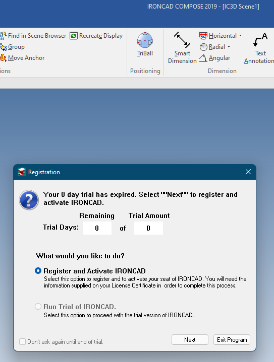
I'm trying out IC Compose with a view to rolling it out to a teammate for collaboration. I'm getting this when I try to run IC Compose (below). (I've come across this before when I felt like checking out IC Compose, but it wasn't a real need at the time so I just moved on.) I thought IC Compose was included with a full install of IronCAD. Do I need to "register" and activate my IC Compose? --Will
-
Ok. Thanks Kevin. Will think through the options. This is obviously troublesome when measuring distances between many interleaved mechanical and electronic components. --Will
-
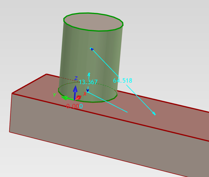
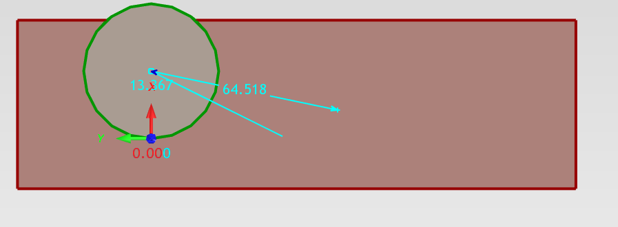
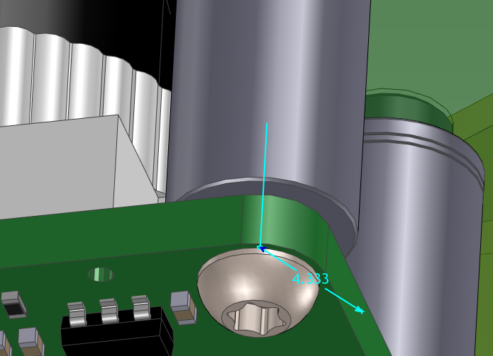
Thanks all. 1. Running a bit ragged these days so I will look into compose in the days ahead. 2. Regarding measurement in IC -- Kevin, I'm still struggling to pick a point on the surface of a cylinder. I've twiddled the "Minimum Distance" and "Linear Smart Dimension" buttons but maybe I'm missing something else. Each time I pick a cylinder, it grabs the centerline, or a point on the centerline. Below are a couple variations. This sort of thing is pretty important as I'm packing some pretty dense assemblies together. Hopefully there is another tip... 3. Harley -- thanks a bunch. I'll have a look at Malcom's vid's in between the flurry...
-
Greets -- I'm the mechanical on a multi-disc. team designing a tightly-packed product. The others need to interrogate my models for PCB component placement. I'm considering Ironcad Compose for this purpose (seems an obvious choice) and wanted to make sure it will go smoothly for the team. I've opened my own models in Ironcad Compose for the first time and it looks nice and familiar to me. However, it seems that measurement behaves subtly differently. The scenario pictured is this: 1. I would like to measure the distance from the a planar surface (treating it as an infinite plane) to the center of a parallel cylinder. In IronCAD this is as simple as choosing "smart dimension," clicking the planar surface, then clicking the cylinder. IronCAD treats the plain as infinite, assumes I want the center of the cylinder, and creates the measurement. In contrast, it seems IC Compose measurements as "surfacePoint-to-surfacePoint" by default. I've looked for settings to change this to behave like IronCAD, but haven't found them yet. Thoughts here? On a hunch, I did a shift-click on the cylinder and IC Compose grabs the axis of the cylinder (hooray for predictability -- good job guys), but IC Compose still assumes I want the surfacePoint on the planar surface, instead of treating the plane as infinite. Shift-clicking the planar surface doesn't seem to help. Picture attached. IC Compose returns 4.333, the distance from cylinder axis to the actual dig'd point on the planar-edge of the PCB, instead of returning the minimum distance from the cylinder axis to the infinite-plane containing the edge of the PCB. 2. Related (though I acknowledge, strictly off topic, since this question pertains to IronCAD itself): Sometimes I *do* wish to grab surfacePoint-to-surfacePoint measurements, but I haven't been able to make IronCAD-proper do this. I've twiddled the "properties" pane during measurement without success. is there a way to accomplish this in IronCAD. Thoughts here? Thanks --Will
-
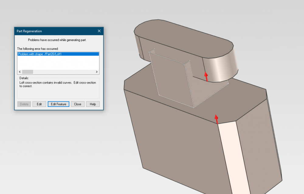
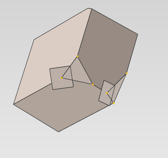
I'm trying to complete a simple loft. I watched Cary's video from another thread regarding twist which was helpful. However, I still seem to be having difficulties... Several questions have resulted: 1. When creating a loft from sections with unequal #'s of curve segments, (for instance, below I have the octagon, which has 8 points, whereas the obround has only 4 points), can multiple points on section1 be mapped/matched to the same point on section2? My attempts seemed to fail. 2. I gather that it's not possible to choose the mid-point of a segment or an arc as a match point (any matchpoints have to be actual segment end-points). Correct? 3. What is the best way to "create" more match points on a curve -- need to edit the section and break the segments up? 4. The reason I couldn't get much further in my investigations is because I'm now getting the attached error (pic) when I simply try to loft between the faces of the block and slot. I've tried a few different settings and I'm not sure what may be amiss. Thoughts? loft error and twist.ics
-
Thanks Cary -- I'm running 2019. I'll try to do a video. Do you have a recommended application for doing so (last I tried, I was on a different machine, and the result was not great)
-
I was trying to make a few holes in a structured part using the triball (created first hole > triball > create multiple > links > [move triball to new location] > P > [return] ) and was getting an error. I thought I was going insane so i created a new scene with both an innovative part (in the background) and a structured part (foreground). No problem with the innovative part. For the structured part, I'm getting the error (pasted below). I've attached the indicated file as well. I'm running IC2019. Any advice here? Thanks. IRONCAD21.0-12-06-2021-03-47-PM-ExceptionLog.txt

-
Thanks Malcom -- I did a poor job of describing my intent. I was actually thinking to do something like the below, where the corner is (sort of) 'chamfered' and the "lengths" are different along the 3 different edges. I did the below by creating points along the edges, then creating a 3-point surface through those points and finally 'trimming' the solid. I was hoping that there was a simpler way to accomplish this with the actual chamfer command, though I realize now that this may not really be termed a "chamfer" ... Any advice here?
-
Greetings -- I'm trying to do a "three edge chamfer" -- that is, to chamfer the corner of a block, with different lengths along each edge... any advice on the preferred way to do this? Thanks, --Will
-
Thanks much Malcom! This is great information, that addressed my issue! Off and running now, with understanding of what's going on. --Will
-
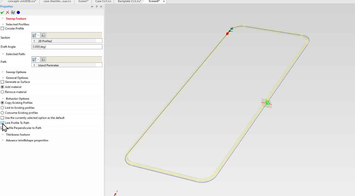
Deep breath again. I'm guessing there is a setting I'm just not aware of. When I try to make a sweep with an off-center profile along a curve, one of two things happens: 1. if check "link profile to path": the profile *flips* about the vertical axis and then sweeps 2. If I *don't* check "link profile to path": then it appears that the sweep misinterprets / inverts the normals of the guide curve and turns the sweep back on itself @ the tangents. Pretty frustrated that simple things like this keep stalling progress for me... I'm guessing there is something obvious, and I'll kick myself. Advance apologies if so. Please advise? oring sweep reversal.ics


-
Boolean (innovative mode) -- Editing the subtracted part?
WPONG replied to WPONG's topic in General Discussion
That would be great. My workaround now is to make a copy of the "tool" part (the subtract) before I execute the boolean, so I can mod things later if needed. -
Boolean (innovative mode) -- Editing the subtracted part?
WPONG posted a topic in General Discussion
When doing a boolean subtract between two parts, the "subtracted" part gets consumed/absorbed into the main part. Subsequently, I see that I can edit the "subtracted" part (change dimensions of existing features). However, is there a way to edit the subtracted part more substantially (i.e. add new holes, features, etc)? Thanks, --Will -
I think I"m tracking. -- where is offset (the .3 or .6 in this case) specified... is there a dialogue or setting for this? Thanks again, --Will
-
Thanks Kevin and Cary -- Trying that setting -- A new question: How is this 'offset' defined? (I looked around in the chamfer definition itself and didn't see anything). This changes the actual chamfer distance on some of the sides, and not the others, and I'd like to be aware of what's going on if possible (see pics). This seemingly silly chamfer is of particular interest to the customer. --Will


-
Thanks all (sorry for delay -- running hard in many directions). Cary and Spencer -- thanks for that -- Yes, I've used a temporary sweep then generated a 3d-intersection-curve, and creating a point. It sounds like this or something similar is the best workaround for now. Maybe an enhancement request? =]. Malcom -- I like that, but the issue is that I may have non-planar surfaces that I'd like to find the pierce point for. Jolizon -- It's been a while since I've been on SW, but I believe it is the same idea. --Will
-
Greetings -- I have a part with a chamfer which is exhibiting irregular / erratic geometry. Not really visible in the pic, but zooming into the model should show the issue. The chamfer is at a junction between drafted surfaces. I've exported and imported as step to try and discern whether this is just a graphical issue, or a geometry issue, and I believe it is geometry. I've attached an .ics scene with both the model and the step export. Is there something I can/should do to improve this situation, or somehow verify whether they are just graphical? (if these anomalies are real, it will be unsuitable for production...) Thanks much. --Will case chamfer issue.ics

-
(Somehow got logged out and was a "guest" when posting. "Replying" here for good measure, to identify myself as a registered user)
-
Thanks Kevin -- Excellent info. Very helpful to understand what's going on algorithmically. Will digest and bear in mind going forward.
-
Very helpful feedback Spencer. Especially regarding path length, which may be an issue for us as well given our situation. So with fear and trembling, step I lightly forward...
-
Greets -- I try to organize my folders logically at the outset of a project, but alas things evolve unexpectedly. As a result, I need to rearrange some folders. I've already run some tests in ironcad with a trial folder structure, and I think I understand what's going on (a key point of understanding: IC appears to use relative paths when searching for children), but since this is a significant project I'm about to clean up, I wanted to run this by the guru's and make sure I'm not missing anything. I have instances with folder structure something like the below. (Greater-than symbols indicate filesystem heirarchy level. Names indicate what-contains-what in IC). I recognize that "Assembly" and "Part" are somewhat arbitrary designations since both are scenes. for purposes here "Assembly" indicates a scene that itself contains one or more external scenes. FolderA > AssyMaster_containing_Assy1234_and_pqr > p.ics > q.ics > r.ics FolderB > Assy1234_containing_Part1_Part2_and_Assy34.ics > Assy34_containing_Part3_and_Assy4.ics > Part1_folder >> Part1.ics > Part2_folder >> Part2.ics > Part3_folder >> Part3.ics > Assy4_folder >> Assy4.ics >> Part4.1_folder >>> Part4.1.ics >> Part4.2_folder >>> Part4.2.ics > FolderB_SUBFOLDER I'd like to make a very simple change. Namely, in Windows, I'd like to move everything in FolderB into FolderB_SUBFOLDER. So, the questions / points to confirm: 1. It appears from tests that "Assy1234..." and "Assy34..." will find all of their children just fine. Always true, or any exceptional gotchas I should look out for? 2. Likewise, for any additional assemblies and subfolders (for instance) within "Part1_folder," parents will find their children as long as the relevant relative paths are preserved. Again, true? 3. "AssyMaster" will break when I open it next, since "Assy1234..." has moved. I should be able to simply locate the new "Assy1234..." path when IC prompts me, and all will be right with the world. Again, true? 4. I'm also open to other suggestions of how best to do this (I recognize that judicious opening of IC could be useful here to manage links, but it seemed simplest to do a Windows move since there are lots of subfolders, and the subfolders often contain non-IC files that would need to be manually moved anyway. Thanks for confirmations, and/or an any other wisdom here. --Will
-
I can also (maybe better on my end -- not another software to install) set up a microsoft "teams" meeting with you if you send me your address... Let me know your thoughts. --Will
-
Okay, I've rebooted and tried again, no change that I can see. I have a meeting a t 2:00 PST, and I'll see if can connect after that. 1. I surmise I'll be downloading the "free version" of the software and installing? 2. What time zone are you in, and what is your availability today? Thanks Kevin, --Will
-
Hmm. No such icon. I've minimized all my windows and reopened IC... I'll try rebooting.
-
I should have mentioned: I do have a scene / model opened and waiting when I click "add FEA." I then select "modal / vibration modes" and also tried "static / Steady state," then "OK." Nothing else happens...