HDEAR
-
Posts
1,021 -
Joined
-
Last visited
Content Type
Profiles
Forums
Blogs
Downloads
Articles
Gallery
Everything posted by HDEAR
-

Restraining holes along the midpoint of an edge
HDEAR replied to HDEAR's topic in General Discussion
Thanks Kevin, That's even better Harley -
Restraining holes along the midpoint of an edge
HDEAR replied to HDEAR's topic in General Discussion
Thanks Kevin, that works and as you say, it's not a big deal to change the parameter table. It will be interesting to see if anyone comes up with another method. Cheers, Harley -
Hi all, Is it possible to use constraints on an Intellishape cut cylinder so that when the parent shape is changed ( non-concentric mode ), the hold will be restrained to the edge midpoint? I am able to constrain the cut cylinder from the edge of the part easily enough but can't figure out how to restrain to mid point. Restraining hole to edge.mp4

-
Thanks Kevin, but no, not really. For example, those lines above refer to reliefs for bends driven by an expression so that when material thickness or bend radius changes, then the relief automatically changes. However that's not all, I have out-bends on the openings which also control the opening so that any material thickness or bend radius change keeps the openings the same. Additionally, I may copy that part and delete openings, or change them. The latter is in fact why chain connection won't work for me. If one of those openings is removed, I could loose the equal distance chain link therefore I have to have one 'dimension set lot' that I know will always be there and and make ALL the equal lengths from that original set. Finally when stretching the part horizontally or vertically, I must maintain the bend reliefs and the way to do that ( we've found ) is to have the constrained sketch from which we want to make the equal lengths to the other sketch parts - hope that makes sense.


-
Dashed lines print as solid lines [SOLVED]
HDEAR replied to MB-Furniture's topic in General Discussion
Hi Kevin. Did you get the same result with Microsoft Print to PDF? I always use this and not the EXB To PDF.drv Is there any major advantage of one over the other?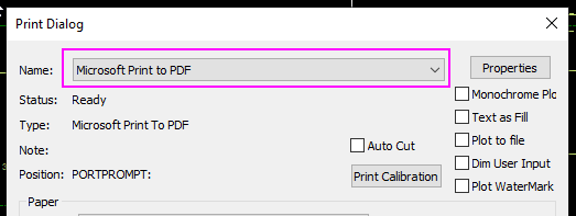
-
Hi all, Is it possible in 2D sketch to use Equal length to apply not only from one line to another, but one line to many others, rather than having to go one individual step at a time? I had a sketch yesterday where I needed to have an equal length of a cutout semi-circle and its relative 'set-back' line and apply that to 4 major rectangular cut-out, each with 4 of these features. That meant that for each of the 4 major cutouts, I had to do 6 equal length actions - it took ages. I know that in Inventor they have the same problem, each equal length has to be done one action at at time. To eliminate confusion about this, I know I have to to a separate equal length action for the semi-circle and a separate one for the line - that's a given. It's just once I click on ( say ) the line, I'd like to apply the equal length to ( say ) 12 other lines, one after the other. Harley

-
Not sure if this is a bug or a weird new feature. Please help
HDEAR replied to SSIMMONS's topic in General Discussion
I thought I was the only one driven nuts by that! I right click the tribal and 'Hide' if it gets too awkward. I'll try Cary's work around next time. I hope IC changes that visual so you don't have to do those extra clicks. I feel they're trying to provide a whole lot of options to suit everyone's demands, but it's ended up getting very crowded in that spot.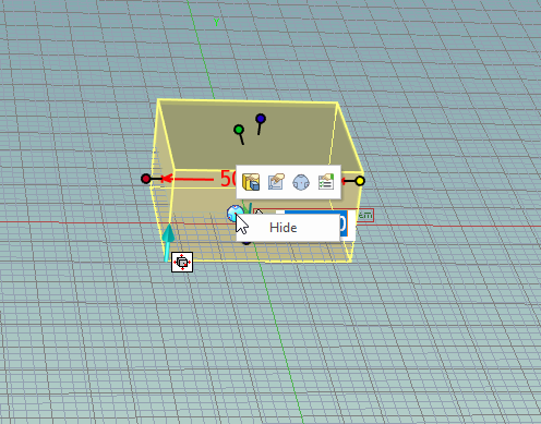
-
Thanks Cary, something I didn't know. I hardly ever use the punch shapes now, but that's a handy tip. Cheers
-
Thanks Cary. That's explained things well. Holding the shift key down was one thing I was missing. I've not used 'edit in flat' before, it seemed a little 'black-art' to me. Are there any tips regarding that please? Thanks once again - Harley
-
Thanks Cary, It's still not working for me though. If I constrain like you say and lock, then when I move the sheet metal length, the hole stays put! There must be something I am missing doing. I had my sheet metal options like you said as well Constraint not holding.mp4

-
Anyone know how it moves the screen without using a mouse?
HDEAR replied to Bertrand Kim's topic in General Discussion
Woohoo - my chance to skite here! My son works for the company in Ireland that designs 3D Connecxion's stuff. I learned this when I won a 3D Connexion Mouse on the Keyshot competition 2 years back. I hurriedly told him I had won this, something along the lines of "Hey look what your 69 year old man has won, I am not so stupid after all" He comes back and says "Oh great dad, nice to see you got something we designed" Aarrgghhh! https://www.designpartners.com/projects/3dconnexion/ I must get a space mouse though. -
Hi all, I'm trying to constrain a cut cylinder in sheet metal. I want it a set distance from the face of the edge. Using Smart Dimension, I can't seem to pick a face that will set the constraint parallel and perpendicular to the face. It picks a point, not a face. What am I doing wrong? Harley Constraining a Cut Cylinder in sheet metal.mp4 Cut cylinder constraint.ics
-
Hi tgjang Right click in clear area of the Ribbon bar and select Customise Ribbon Bar Select Home, Click on Help and training then 'delete' Harley


-
SOLVED! - Helix along a curved surface - is this possible?
HDEAR replied to HDEAR's topic in General Discussion
Hi all, I found this video by Cary made some years ago, and also mentioned by Tom in a post a while back. -
Hi all, I am wanting to produce a spiral wire along the surface of radiused tube. The final result will be to mimic spiral flexible ducting. If I can run the spiral along a surface, then I will create a ( say ) 0.5mm da wire from the 3D spiral curve and carry out a Boolean action on the duct and wire then shell it. That's the idea anyhow. So how do I create that spiral along the surface in the first place? Duct dia 153mm Bend radius 1000mm Spiral wire pitch 50mm

-
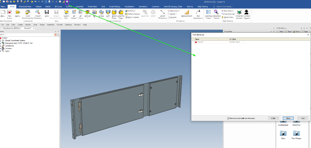
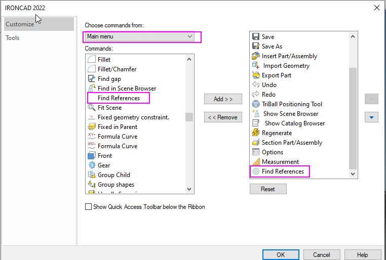
This may be obvious to a lot of you, but just in case:- I often have to find references in a file and it's a PITA using Menu -->File-->Find references all the time. I have added the Find references to the Quick Access Toolbar. It has been a life changer

-
Structured parts - referencing 2D sketch positions
HDEAR replied to HDEAR's topic in General Discussion
Hi Bertrand. That file can be found in the Steel Frames Catalogue. Harley
-
Structured parts - referencing 2D sketch positions
HDEAR replied to HDEAR's topic in General Discussion
I think I ay have worked this out. If I rollback and Edit the 2D sketch, make the 3D wire and the Body visible, I then see that constraints are added from the 2D sketch against the 3D wire. The main constraint seems to be the bottom RH point which looks like a 'Projected constraint'. The other constraints are coincidence. Have I nutted this out correctly or is there a better procedure? Also the Triball doesn't seem to work when trying to shift the 2D sketch position around. Is that normal? If so, how do you position the 2D sketch? Lastly, the Constraint symbols are so tony, you almost need a magnifying glass to see them ( 27" screen or laptop ). Is there a way of enlarging them? I almost need my 2.75x reading glasses on to have any chance of seeing them. Thanks Harley -
Comparison of steel beam structure between IronCAD and SolidWorks.
HDEAR replied to tgjang's topic in Tips and Tricks
Hi Tgjang, Good comparison. Do you think you should add the gussets to make it a complete comparison?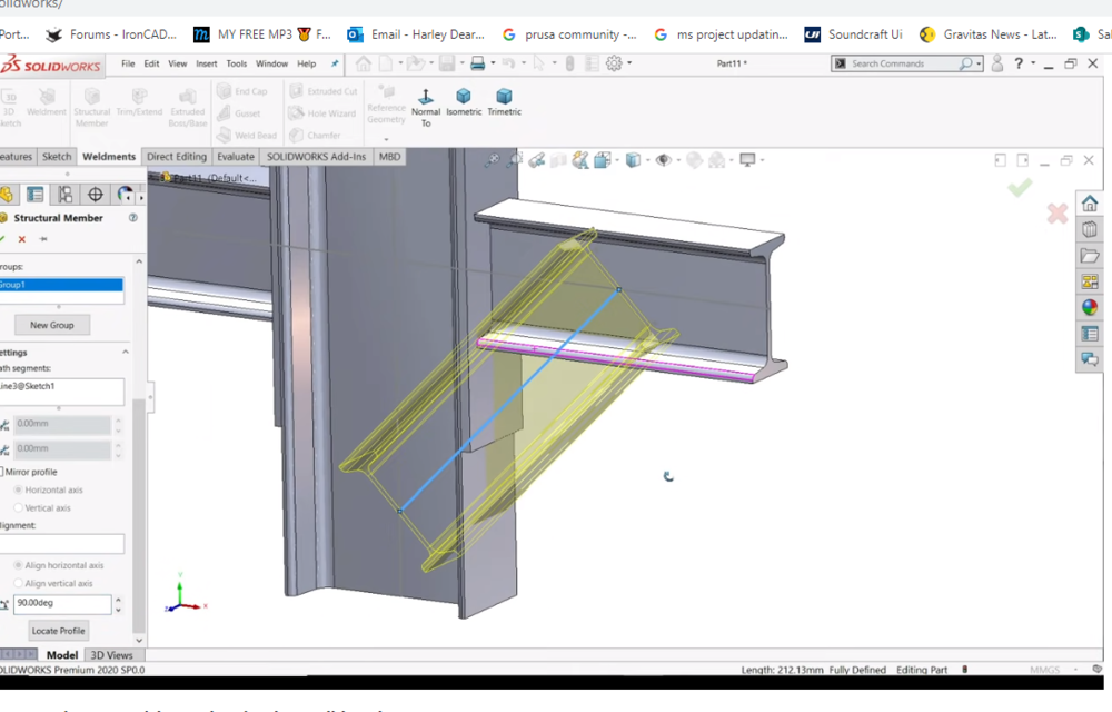
- 1 reply
-
- 1
-

-
Hi all, I am learning about structured parts. I thought I'd start with the inbuilt Steel Frames catalogue and got hold of Cary's 2015 video ( referenced below ). I am trying to work out how the 2D sketch is attached to the assembly and how the two end points are referenced to the rest of the assembly. How does on go about that please? Thanks

-
Oh, I never thought of trying that first. Many thanks Cary
-
Hi all, I have a cropped view and want to do a detail of one corner, but it doesn't work for some reason. Is it all in the way you hold your mouth to get it to work? Harley Detail not working on crop view.mp4
-
This is what I get every time I open a DFX or DWG in CAXA. I just hit 'Cancel all' but it is annoying having it come up every time I must say. Harley

-
*SOLVED* CAXA - Adding similar Detail Circles to drawing
HDEAR replied to HDEAR's topic in General Discussion
Huh! It was simple. CTRL-C and then CTRL V DOH!- 1 reply
-
- 1
-

-
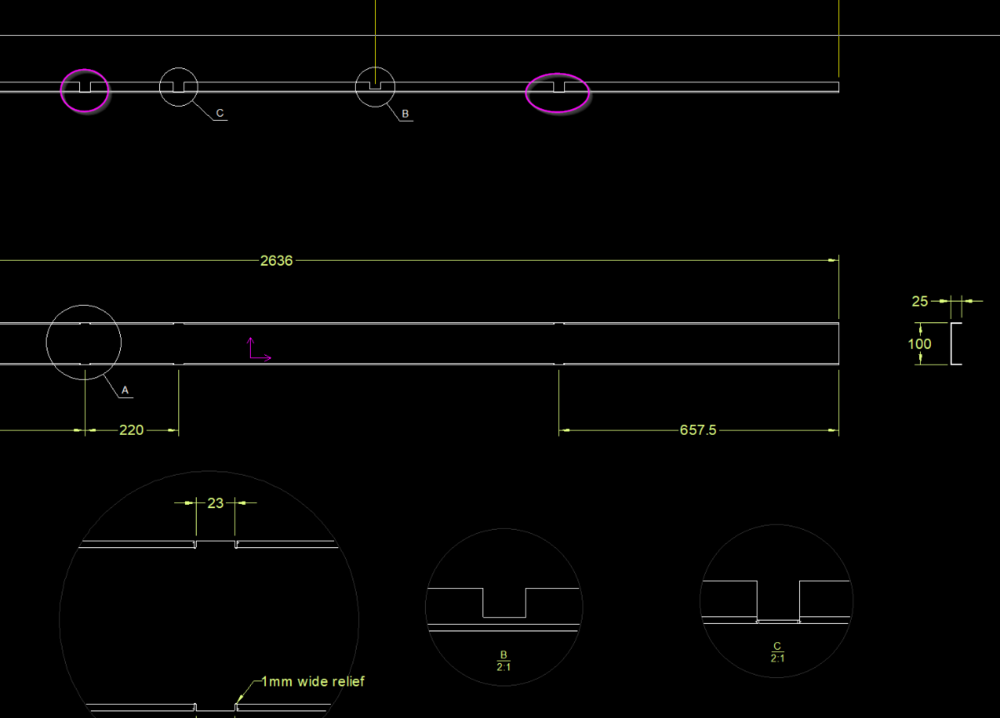
Hi all, Is it possible to add additional Detail Circle call outs that reference to the same detail in the drawing? For example, in view below, I have 3 references which relate to one type of cut-out and on that relates to another. I want to have another two '"C" Circles on the elevation ( in purple ). Do I have to manually draw these? If I start a 'detail action', of course it will label the circles D ad E resp. and also make new detail views which I don't want. Thanks - Harley