HDEAR
-
Posts
1,019 -
Joined
-
Last visited
Content Type
Profiles
Forums
Blogs
Downloads
Articles
Gallery
Everything posted by HDEAR
-
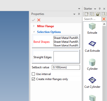
OK, when I get time, I'll have a look. The way I see it at the moment you're better off to design in 3D the 4 separate parts then do a DXF off each, including the unfold. When making mitres, there is an option to create mitre flanges only. This allows you to make the mitre flanges that are all individual as opposed to linked so that if you alter one, the others don't change. The flip side of the coin is that if you want to alter more than one, you have to alter each individual one because they are not linked. Harley
-
What's the largest sheet size and how will you join them ( butt weld, seam weld, fillet weld )
-
Thanks Cary and Kevin, Darn! I forgot clean about the Smart Dimension constraint. Thanks for the reminder. Good to know I wasn't imagining things though regards that point to face constraint. Harley
-
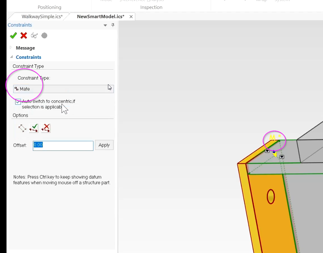
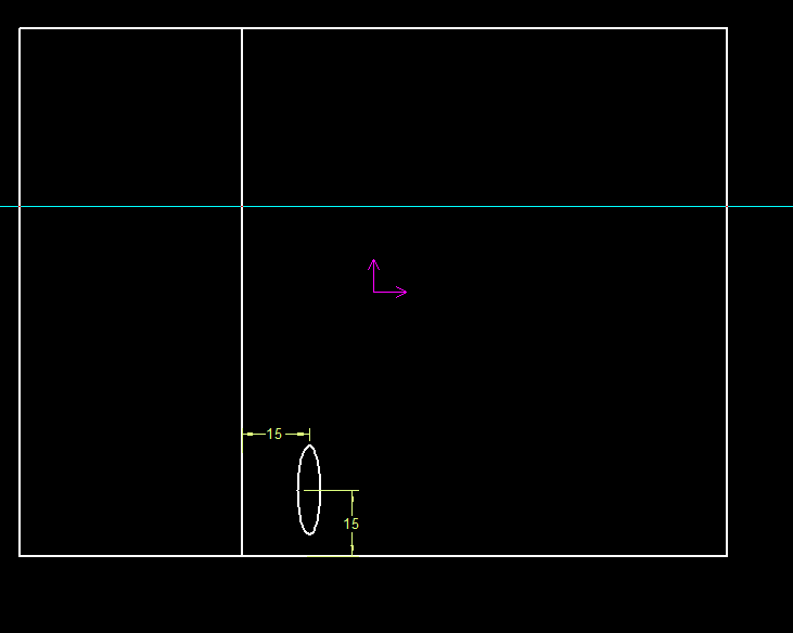
Hi all, I am having trouble getting the distance constraint to face working - see video. Here's where I need the constraints. What am I doing wrong? There used to be a Mate constraint which you could set an offset - it's not there any more. That used to work with this sort of action I need. Distance positioning constraint to face not working.mp4 Blade positioning.ics
-
 Nice work Tom, very realistic.
 -
-
Thanks Dr Seuss

-
Structured Frames - Adding Custom Shapes and Sizing Data
HDEAR replied to Malcolm Crowe's topic in Tips and Tricks
Nice way to finish off the weekend Malcom. Thanks. This so helpful as I have about 10 different extrusion shapes I'd like to use in this new feature. @Cary OConnor I reckon videos like this should go into the IC Academy training video list. Harley -
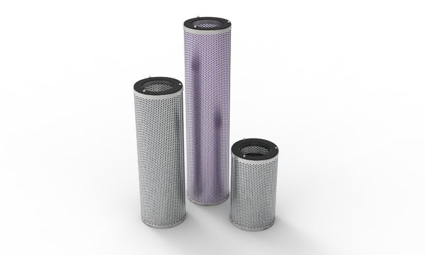
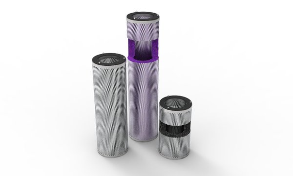
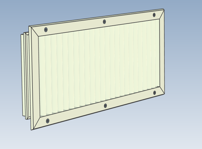
Thanks for that and spending your time to make the video, Yes, a pity the 45 degree angle you made in the complete profile doesn't come across. Also, I'd need to have 45 degree mitres on the corners. I aim to end up producing this ( my attached profile being the outer frame ); Harley
-
Thanks GNaesland. You mentioned you tried this. Did you use that profile I posted in my original post, or something more simplistic of your own? With this particular profile, there's only ever one size in terms if the underlying 2D sketch. It's making the overall frame size using 4 lengths of that extrusion into a rectangle that I am trying to achieve. Therefore is it necessary to totally restrain that underlying 2D sketch of the profile? Harley
-
Well... now I know why Hi all, I can't seem to get mate constraint to work between faces ( in video and model attached ), like in training video below. Mate constraint trial.mp4 mate trial.ics

-
Hi Cary et al. In your structured weldment creation video, you mention that users can add their own sized weldments into the table found in... C:\Program Files\IronCAD\20XX\AppData\en-us\Steelbars labelled SteelFrameData.txt Is it possible to add your own extrusion shape to this table? For example the shape I have attached. Harley DDL-20 Frame.ics
-
Thanks Kim I forgot that. Harley
-
Sorted! Now linking.
-
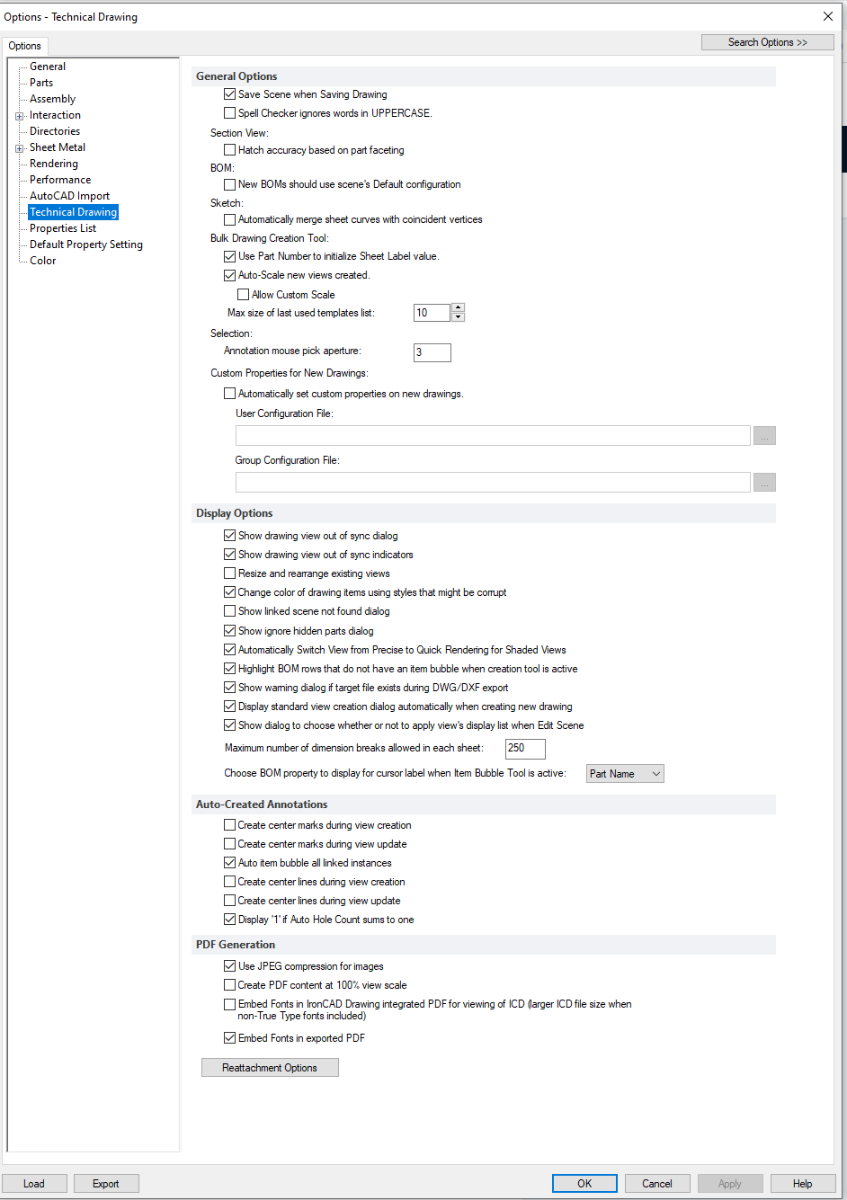
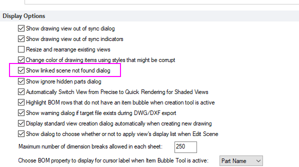
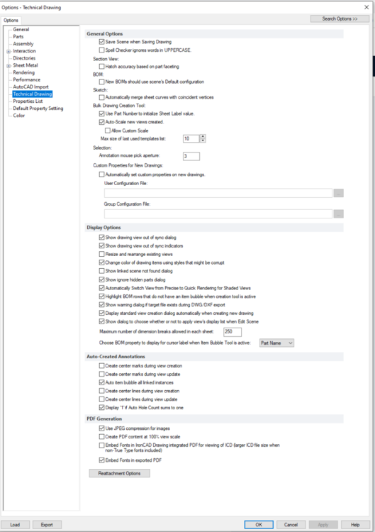
Here's my Tech Drawing settings
-
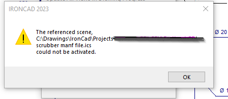
Thanks Cary. The latter I am afraid as I need the association with the 3D ICS. Next question. I have lost the file association between the IICD and the ICS. In ICD I went into to View---> Edit scene but that wasn't helpful. I then went into Home-->Update all Views, and usually ( if I recall my ICD days right ) there's a menu that comes up saying that it can't find the ICS view and gives you the option to look for it. However I don't get that question, instead I just get this How do I go about re-associating the ICD with the correct ICS please? Harley
-
I'm picking that the answer will be "No" or "only with extreme difficulty" but I'll ask anyhow; I have a whole set of ICD drawings ( 2018 ) I need to amend and I wonder if it's possible to easily convert ICD into CAXA ? Harley
-
** Resolved ** Mitre on bend not showing, don't know how it got there
HDEAR replied to HDEAR's topic in General Discussion
Thanks Kevin, Yes that makes sense now. I recall the sheet came from an even more previous design that had miters all the way around. The 'MitreGhost Mystery' is BUSTED! -
** Resolved ** Mitre on bend not showing, don't know how it got there
HDEAR replied to HDEAR's topic in General Discussion
Thanks for the quick response Kevin, I actually need to get the mitre back as well. Your fix is helpful, but I need to redo the 2.1mm corner reliefs and then add either a corner break of extrusion cut. Which doesn't take all that long I must admit. I was actually more curious as to how the original 45 degree mitre got there in the first place seeing it does not appear in the scene tree at all. It's almost like it is a 'ghost' feature Harley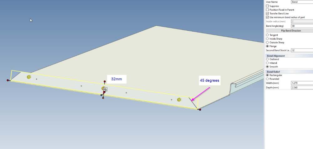
-
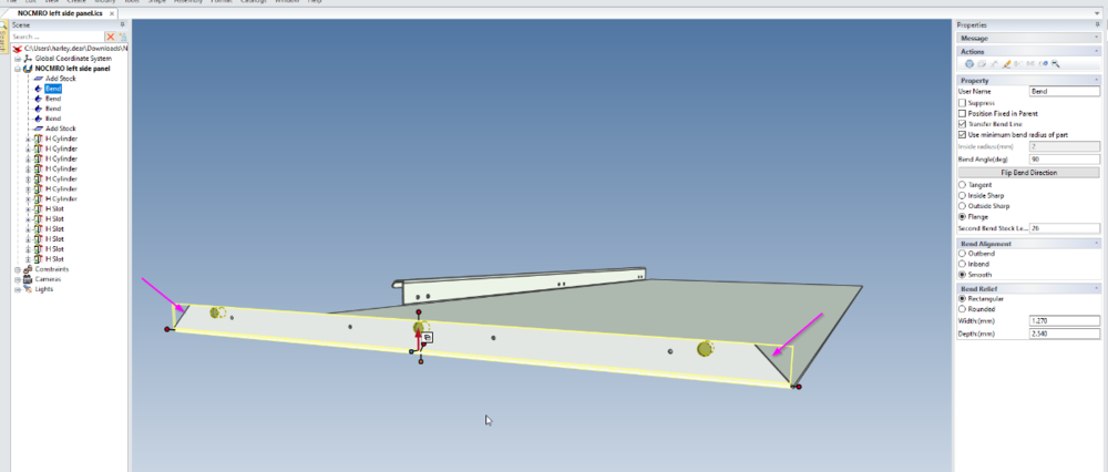
Hi all, Well this is weird indeed. I was re-modelling a sheet metal part from a unit I had designed 2018. I needed to add some fixing holes to a bend, and as a result need to extend that bend from 26mm to 32 mm. When examining that bend it has a 45degree mitre cut on it but that cut ( corner relief or cut extrude ) doesn't seem to appear anywhere on the scene tree. If I make the bend 32 mm, the mitre cut angle is wrong ( it needs to be 45 degrees ) I can fix this with an extrude cut ( messy ) but I can't for the life of me figure out how that 45 degree mitre got there on the bend in the first place. Harley NOCMRO left side panel.ics
-
I had this problem when I first downloaded IC2023. Without anything else open, I started a new empty scene, floated ( undocked ) all the docking windows ( scene, properties, search etc ) and then redocked them in the area I wanted and finally resized. Then I saved the UIC, closed IC down, shut my computer down, re-booted and it now works perfectly. I think I even made a post about it.... Harley
-
CAXA Draft - dumb question! - how do you do a fillet or a chamfer
HDEAR replied to HDEAR's topic in General Discussion
Thanks Malcolm. -
CAXA Draft - dumb question! - how do you do a fillet or a chamfer
HDEAR replied to HDEAR's topic in General Discussion
Hi Kim, I sent an ICS of this in the other post I made.