HDEAR
-
Posts
1,021 -
Joined
-
Last visited
Content Type
Profiles
Forums
Blogs
Downloads
Articles
Gallery
Everything posted by HDEAR
-
Brilliant - Thanks Malcolm
-
Highlight dimension if not already selected and use CTRL-F and CTRL-R shortcut keys to flip inside-out and left right resp. Also CTRL-0 ( zero ) is handy when you have a dimension like 97.976mm that you want displayed 98mm
-
Between Tom and you, with your spiral mixer and his 'globe on bottle', you guys have to take the prize for the oddest stuff that has to be drawn
-
Thanks Kevin.
-
Is anyone else having problems with editing distance of added stock to bends using the shape tool? In the attachments, you'll see I have tried to alter the distance of stock on the bend from the side on the original from 1.58mm to 3. After pressing enter, the triangular node shifts across, but the bend stock stays put. The only was to alter the bend stock length is to use the sizebox, which in this case is inconvenient. Any advise welcome - thanks. Harley SM_bend_stock_alter_distance_problem.ics

-
Thanks all - very helpful Cheers
-
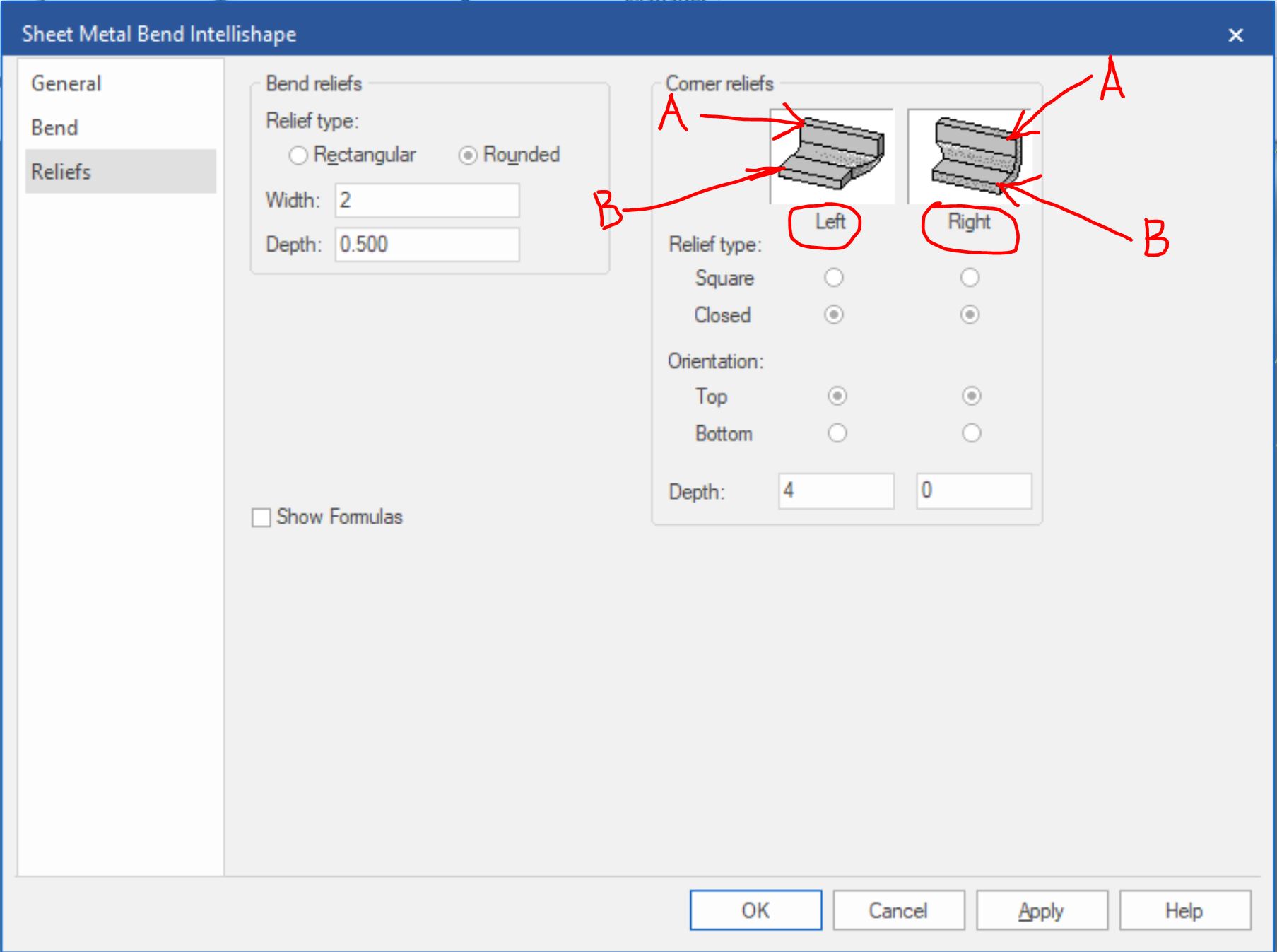
I'm trying to work out the rhyme or reason on which side the bend corner reliefs refer to when making them. So far it's pretty much a 50/50 raffle on which side I pick turning out to be the side I require the corner relief to end up on. Is it; the left/right viewed down on the flat stock BEFORE making the bend, or the left/right viewed from inside the bend ( looking away form the stock ) once it's made, or the left/right viewed from outside of the bend ( looking toward the stock ) once it's made? I am guessing it's something simple I'm missing or maybe some instruction I have not read. I've labelled the attachment to aid explanation. Thanks and cheers
-
Hi Tom. I have had trouble previously with profiles on corners unfolding like hot custard, so for bends like these I simply make the bend to length of zero, add stock and then edit. The advantage is this works without fail. The disadvantage is that if you increase the length of the box/fold/stock, you're up for another edit of the stock profile - normally just a shift position though. I did this ( make the bend to length of zero, add stock and then edit) to your fold and voila;


-
I'm having to learn solidworks as head office uses it and I need to have a little knowledge of how it works etc to send them converted files from IC. So, during my learning I came across solidworks' gusset feature. It's quite impressive and takes very little time, The gusset features starts at 9:40 in this video
-
Yep - here is the back of a Magnehelic Gage I drew up just for the hell of it and rendered in Keyshot. It's almost real.
-
Keyshot is well worth the money. Here's a galv hooded HEPA terminal. The trick is to get the scale of the image right. By memory, it's about a 20th of the standard image in the keyshot library, but it only takes a few seconds to get it right.

-
Hi Jonas. I have used this IPRO tool but the settings keep getting lost. Any clues how to make this stick permanently?
-
Thanks all, I didn't realise that Compose was now stand-alone. Too much to remember and brain cell numbers in decline
-
Hi, I am getting asked for 3D files in eDrawing ( which I understand is *.easm ), a solidworks product. I have the free download of eDrawing so I can see why they like it. Does IC gave a capability to export a file that eDrawing can use? I know we have Compose, but clients are reluctant to use that when they already have eDrawing. I haven't downloaded Compose as I don't need it really so I don't know how it works. Is it a stand-alone product or is it the full version of Ironcad to download, but with restrictions? Many thanks Harley ps - Oh, on the off chance I can get clients to download Compose, is there any special format I use to give them a file, or do I just send them the full blown *.ics file?
-
Yes it did - thanks a lot everyone.
-
Thanks Darius
-
Thanks Kevin - I emailed you the template.
-
I like the idea of bulk view creation for icd. as advertised on the web site ( see first attachment ) I tried to modify and use one of our standard company A3 templates with first angle projection and save this for use with the wonderful tool, but failed miserably. Are there any 'how to's' , tips and tricks etc on how one goes about this? ( make your own template foe bulk creation ) It seems to come unstuck when I want to add more view to my template and/or copy my template over the existing 'VT Ansi mertric' templates. Also, the path C"\Users\btstaff\.... doesn't seem to exist in my laptop for me to be able to access views. Obviously, I'm heading down the wrong garden path. Any help appreciated. Thanks


-
Yes, I have IC MECH so that's a good solution even though it's the tail wagging the dog in my example. I can make that work and I've just started a project I can trial it on. Thanks for taking the time to come up with a solution. Cheers
-
Solved it! It's all about how you place the wrapping bend onto the first piece of stock you start with and then pick the distance point to the last bend - sounds 'double-kiwi' I know, so I made the attached crude instructions to explain


-
Thanks Kevin. Your first method works great for when you want to copy or link a series of holes either in a pattern or along a common centre line. That will make quite a difference in my s/m assemblies where multiple fastenings are required. The second method ( using profile and projected constraint ) doesn't work with copy or link, but for single profiles, it's great. What about linking holes with different diameters? For example I have sheet metal panels with flanges that are Tek-screwed ( self tapping screws ) together. The master flange ( that accepts the screw ) has 5mm dia holes and the mating flange has 2mm dia holes which act as pilot hols for accurate alignment. Project constraint can't work as holes must be identical in dia and fastener assembly doesn't work as the fastener dia dictates an identical size hole in each flange ( perhaps I could try and find a stepped fastener?). Any ideas how to constrain two different sized holes and be able to copy/link? ( have the cake and eat it too )
-
Thanks Kevin - much appreciated. I think it's the way he did that 'closing wrap bend' that made all the difference. I can't seem to replicate that at all with any of the SM tools or IPROXT tools. Funny how these things drive you batty until they're resolved
-
I tried following Cary's advice regards making mitre bends by using a bend to close the last bend with the first. I can't get the right result. There seems to be a difference in the 'wrap and close bend' that Carey applied to my ''wrap and close' bend. To Quote Cary "You have to close the loop. Ad a bend on the last stock to wrap to the first. Then add the mitre." Is it the sequence I am doing things? Is it the type of bend I am using? or the typ of stock with bend????. I have tried for a couple of hours now to get this right but it has me beat! Any help appreciated and a video would be priceless! Edit! I tried rebuilding Cary's closed mitre with different frame dimensions and material thicknesses and couldn't get that to work either. I have attached Cary's fix from his last post. FILBX_TESTR_610610_426..ics HFrame.ics


-
Brilliant! Thanks Cary. If I wanted to make two piece frames to get the square, how do I get the Add Mitre to make the angled cuts at each end? I have hand drawn an unfolded and completed to explain.


-
I am struggling to get add mitre to work on a simple s/m frame. The frame starts with 100mm wide flat 645 long and its then folded three times to form a square. The first bend needs to form the mitre and I need to have the mitres at each end of the unfolded strip. I can make the main bends on the strip and fold the main square shape and then add the first back bend then the third bend after that. When I perform the Add Mitre, it will work only on two straight edges and won't let me finish the last one. If I try and make the frame in two pieces ( extra welding ) the I still get both ends of the unfolded strip. Maybe I am doing something wrong. Is there a way to draw the frame, use the add mitre and get all the mitres to perform, ending up with three V type mitres on the unfolded strip and the two part mitres each end? We make these frames so it is possible to physically do it. The back folds are done in two hits along full length with break-press then the small folds are done to bring the frame to square. Any help appreciated. Cheers HFrame.ics