


Nickul
-
Posts
98 -
Joined
-
Last visited
Content Type
Profiles
Forums
Blogs
Downloads
Articles
Gallery
Everything posted by Nickul
-
Will, You can also use a co- ordinate system to section a model. Under the feature menu, create a new co-ordinate system and position one of the planes on your desired section. Right click the plane and choose, Create Section Profile. This creates a 2d sketch section, it does not cut the model, which I understand you are asking about but this is sometimes an advantage. By changing the size of the plane also controls the section extents, i.e. you can just section a small region of an assembly. By opening the sketch with it displayed on-top of the 3d model may reveal issues. The other advantage of this method is you can copy using the triball, 20 or so planes 50mm apart and quickly create multiple sections without having to wait for the parts to regenerate. Nick
-
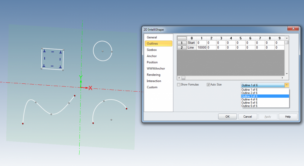
Tom, one last method I use to troubleshoot issues on the sketch, is using the outlines list within the 2d cross section properties dialogue. While in the sketch, right click and choose, Cross Section Properties, and then Outlines. Drop the combo box down and in the example shown it lists 6 outlines. the first two are always the X and Y axis. So I have four present. This way you can track down any troublesome entities. Now this is probably not going to help with your example, too many to count !
-
We use the Pointwise mesh generator for CFD, and within it has a handy feature for selecting adjacent faces. So you set up a angle threshold first, lets use a cube as an example with one of its faces split into two coplanar faces. If you want to just pick those two faces then you set your angle threshold to 89deg, then select one of these faces and click the button "All Adjacent" and it'll pick the connected faces lower than 89, i.e. the two coplanar. But if I then set the threshold to 91, repeating the command it'll pick all the cube faces. Nick
-
oh sorry I see, I was thinking you meant a faceloop of edges.
-
having selected an edge the tab key will select the adjacent smoothly connected edges. also select an edge and press Alt and a , this brings up the advanced curve selector but I can't quite work out how to select a loop using it.... Nick
-

how to design a segment bend tapered in IronCAD?
Nickul replied to dleczynski's topic in General Discussion
1. export the dxf surface model straight out of plate n sheet, and then "convert to solid" when in IC so you can grab it with the triball. 2. Create from scratch, this shape is revolved cones, cut at the correct angles. -
ahah, so I've changed my "scene background" to black and my 2d constraints are now much easier to see, thanks. But why is it called "scene background" ? It has not changed the colour of the 3d scene background at all. (this is good in this particular instance) but what has it changed elsewhere.... thanks Nick
-
How do I change the colour of 2d constraints that have had expressions applied. It seems that having put an expression on it changes them to a tan colour, and as the tan scene background is one of my favourites it kind of make it difficult to see them. You can now switch the 2d constraint background on and off but how do you change the colour of the background.... its set as turqoise but with a tan colour constraint this is awkward to view. see image thanks Nick
-
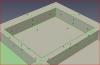
I have a part from a customer and the hole centres are defined as crosses, (i.e. about 500 crosses have come through as a "wireframe part". So I'm looking for an easy method to create the holes in the 3d scene using the crosses to locate the holes. If I create a view in CAXA and explode this I can then manually copy and then paste every hole, reimport this back into a sketch and extrude and subtract to make the holes. kind of time consuming... While in CAXA though I thought what if I create points at the crosses I can then reimport the points and then create a sketch pattern. but I cannot reimport the points from CAXA , I've tried dxf,dwg and exb format but they do not come through, Bug / ER ? Any other clever ideas from the community thanks Nick
-
I can't get this to work at all. i think the crux of the issue is when I use the project constraint to project the 3d Point, onto the Guide curve plane, and then recreate the guide curve, the guide curve vertex does not follow the project constraint. So if I manually move the 3d point myself, and then go in and edit the guide curve the projected constraint point has moved but the guide "line" vertex has not. How do you tie the two together? I.e. simply creating a project point using the constraint project, how do you lock the end of a line to follow that projected point ? UPDATE : I've just answered my own question, you have to create a coincident constraint between the project point and the end of the line - so then I'm baffled why its not needed in the video.... So, got it working now thanks Nick
-
both superb suggestions thanks. Dragan - i always forget about the intellishape reshaping options, I have probably never used them before. Malcolm - very interesting as you can see I tried to pattern the blend but it would have none of it, but the key is pattering the block and pattern together. I wish the error message could have said that... thanks Nick
-
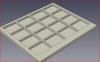
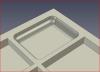
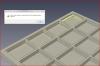
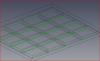
I'm trying to select the relevant edges to blend each of the pockets in a pattern. See image, , so that I get this, , but picking the correct edges over the entire part is proving tricky. Select by autofeature or intellishapes, gives this, i.e. it tries to blend the top of the web. Patterning the blend almost works but then throws up an error, The advanced the curve selector does not really help in this case. Perhaps the best method is to switch to wireframe and use the box select and drag bottom right to top left to get open window mode and select the correct edges, but this is fiddly, and does not seem to select the edges that are end on, thus you have to look side on and then add the remaining edges. This is quite tricky with a part that is significantly longer than its depth. Any ideas how to easily select the correct edges to blend the pockets. I have many different parts to do with this problem. It did occur to me to blend a box (the size of the pocket,) and then subtract and then pattern this from the main block.... I may do this. thanks Nick
-
is this with the new version?, I don't seem to have this with 2014, and I needed it ! thanks Nick
-
Is NEI NASTRAN still available for IRONCAD
Nickul replied to Malcolm Crowe's topic in General Discussion
just two days ago I discovered this too, I have contacted a Nastran reseller here in the UK to ask what the state of play is. The expert version of "In CAD" would have been a good product for us. -
thanks Cary, that has sorted it out. Nick
-
I have had a go at producing bend lines in both of the drawing environments as per Josephs tutorial in the tips and tricks section of the forum. So I created my loft shape And then bring the view into an ICD drawing, , and each bend is nominally 10deg, as I have ten bends to a corner. but when I bring it though to CAXA, each of my bend is 170 deg ! , what am I missing, I have tried a few things to to no avial. I tried reversing the intelishape direction of the unfolded shape, but this just results in no profile whatsoever in CAXA just the bend labels. (The 170 deg seems to be the correct angle minus 180) thanks Nick


-
or use the button at the bottom of the screen, see image, another handy method is to select your part first, right click and then use "Zoom to Selection"


-
use the fit scene button to rescale your zoom, when changing from large to small parts. Nick
-
the blend and chamfer tools support it too, and also when the selection filter is set to edge it can be brought up, and then you can extract curves, (i.e. rather than starting the extract curves command and then bringing up this tool,) Nick
-
ahaa, Alt A , and up it pops. nice tool, thanks Nick
-
How do you access the advanced curve selector ? I press "A" when I'm in the patch command and nothing happens. I found this topic (see link below) by Karen, and it suggests that it did work. Now with 2014 it does not seem to. http://www.ironcad.com/support/community/i...curve++selector So has the IC installation not setup the A key as its shortcut key for this tool? Ok then so I go to the tools / customize / keyboard settings and try and find this tool but its hiding somewhere , and I can't find it. any suggestion as to where it is ? thanks Nick

-
in Caxa, I'm experimenting with the Technique Requirement function and when I click in the larger white box at the bottom of the dialogue box (see image with the red circle), this window disappears and the main IC window is left hanging. Its although IronCAD is waiting for another user input , but no other window appears. All that is left is to manually stop IronCAD with task manager. Am I missing something or is this a bug? thanks Nick IC 2014 64bit , on Vista


