Malcolm Crowe
-
Posts
1,760 -
Joined
-
Last visited
Content Type
Profiles
Forums
Blogs
Downloads
Articles
Gallery
Everything posted by Malcolm Crowe
-
 CAXA DRAFT provides users with a lot of control regarding the User Interface, so that it can be customized according to user preferences. One of the components of the User Interface is what CAXA refers to as the "Instance Menu" (command options). This is activated whenever a command (or tool) is started and will display the various options that are applicable to that command (or tool). Attached is a video demonstrating how to position this "Instance Menu" wherever you want, whether that be floating on the screen or docked within the Status Bar at the bottom left. Note that for some commands (or tools) the options displayed in this "Instance Menu" might change during the command (following selections on the screen). So, keeping a watchful eye on these options within the "Instance Menu" is something to be mindful of. Malcolm CAXA - User Interface - Position of Instance Menu.mp4
 -
If your desire is to set the default "Current" layer for any new drawing created, then Kevin is correct. You need to set this "Style" information within the "Template" that you are using for creating the drawings. This is demonstrated in the attached video. I've also attached a document that explains what information is stored where regarding CAXA DRAFT. Malcolm CAXA - Setting the Current Layer in Drawing Templates.mp4 IRONCAD DRAFT - Setup Styles and Configurations - 20221118.pdf
-
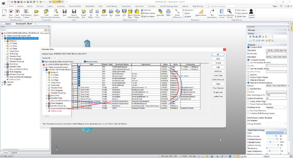
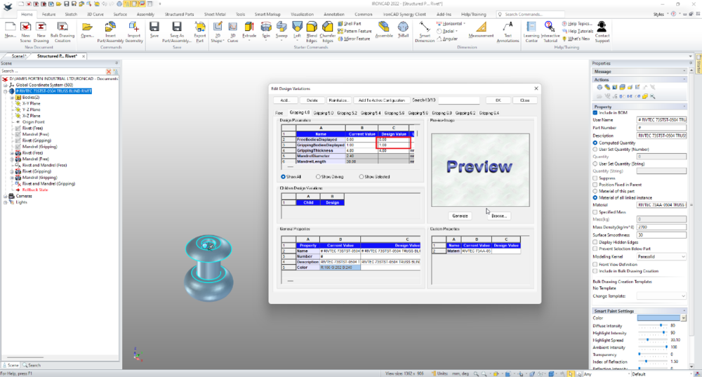
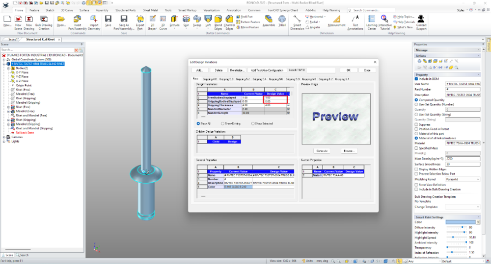
Hi Harley, Suppression Parameters are "Scalar" type parameters that toggle on and off using "0" and "1". At the Part Level I have created 2 scalar type parameters, the values of which are being used to drive the Shape Level Suppression Parameters. See the attached image of the Parameters used in this part. The Design Variations are then feeding values ("0" or "1") to the Part Level Parameters. Attached are images of the "Free" and "Gripping 4.8" Design Variations. Note the reversal of the values used for controlling visibility of these bodies. Malcolm
-
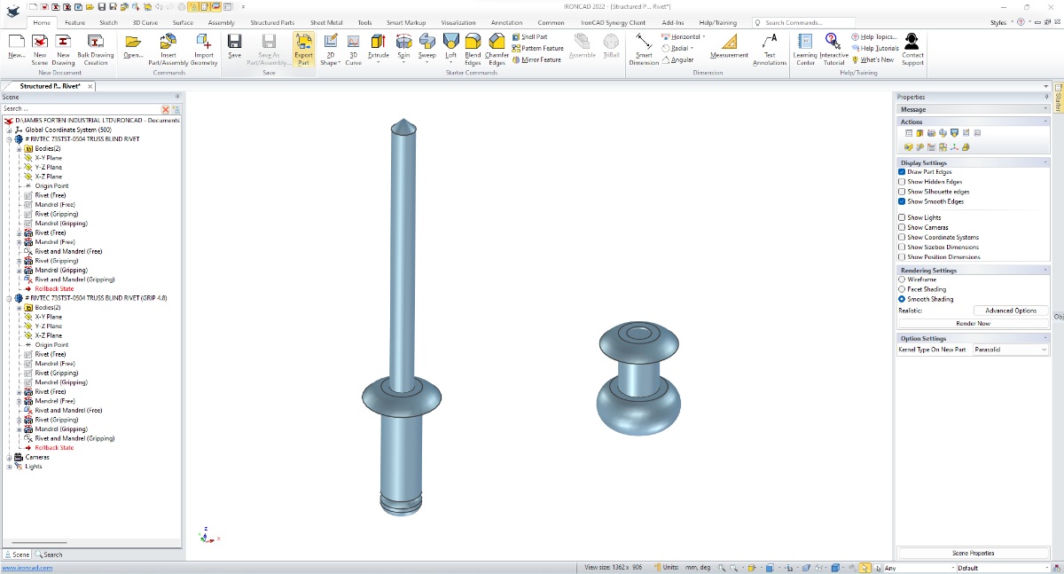
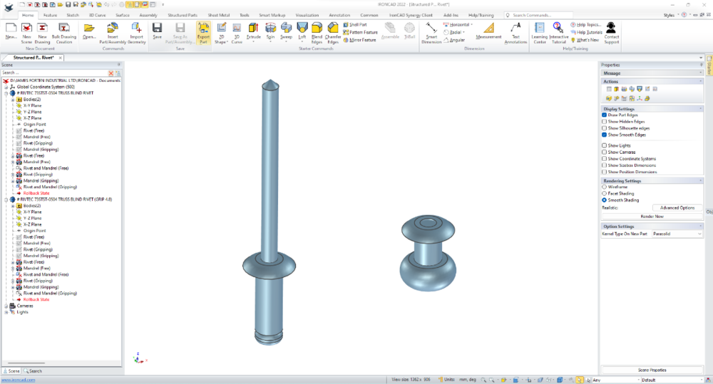
This example is of a Blind Rivet that has been created as a Multi-Bodied Structured Part, so that the Rivet can be displayed in its "Free" state or in its "Gripping" state (with a defined range of gripping thicknesses). Important features within this model are the "Delete Body" features. These features have "Suppression Parameters" for toggling them on and off. These allow us to control which 2 of the 4 bodies are displayed at any one time. Malcolm Structured Parts - Multi-Bodied Blind Rivet.mp4
-
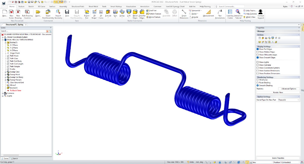
Spring design (whether tension, compression or torsion) is another application where we always use Structured Part mode (with parameters), for displaying the springs in different states or positions. This example is of a Dual Helical Torsion Spring with some additional features. Malcolm Structured Parts - Dual Helical Torsion Spring.mp4

-
CAXA - Baseline dimspace(gap) in dimstyle?
Malcolm Crowe replied to Bertrand Kim's topic in General Discussion
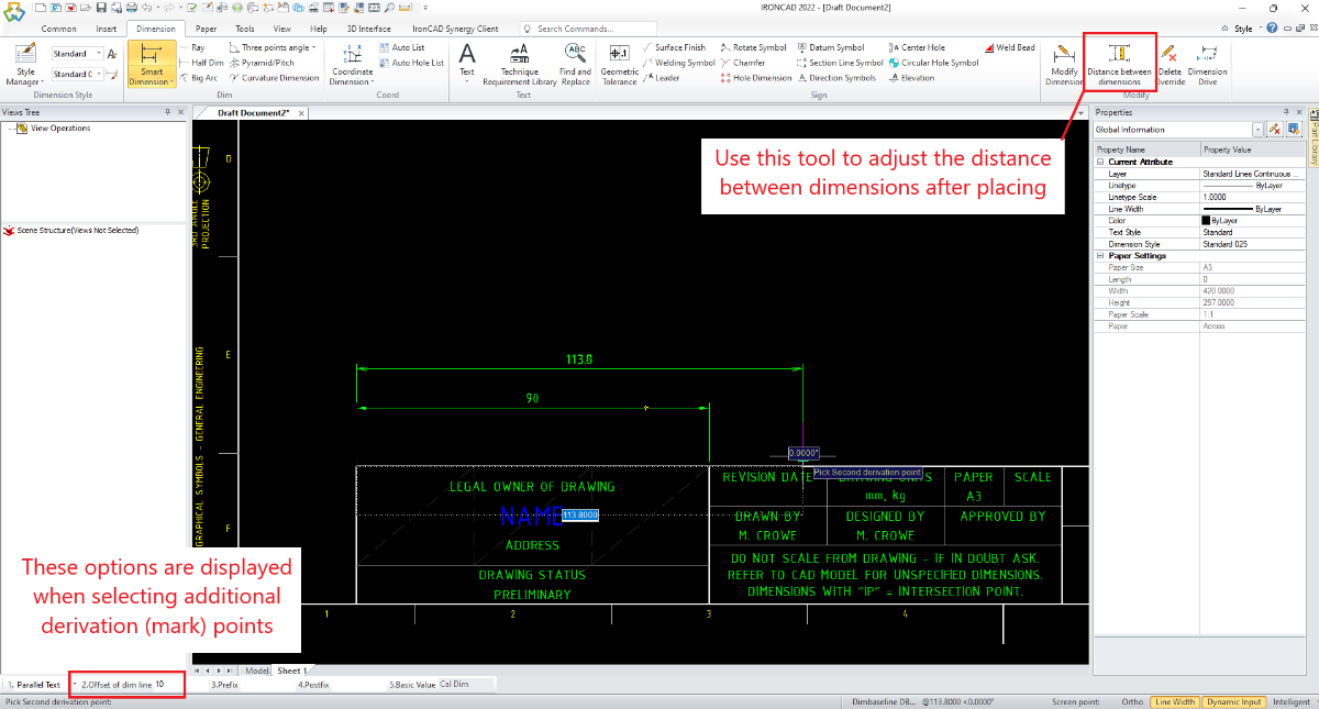
Dariusz is correct regarding the distance (gap) between the text and the Dimension line. If you want to control the distance between the Dimension Lines, then this is controlled by the options displayed in the bottom left of the screen. Specifically, when you place the additional derivation (mark) points, See the attached image. If you want to adjust this distance after placing, then there is a tool on the Ribbon Bar for this (this is also shown in the attached image). Malcolm
-
CAXA - centre-line extension dimensions on slots
Malcolm Crowe replied to HDEAR's topic in General Discussion
Hi Harley, The difference in dimension values could be to do with the "Dimension Precision" that is being applied to the dimension; where sometimes CAXA might be rounding up and other times it might be rounding down. This is demonstrated in the attached video. However, while preparing this video I discovered that the "Midpoint" Object Snap isn't working correctly if selected from the Object Snap Menu (when you press space bar key). However, if you use the keyboard shortcut "M" for selecting the midpoint, then this works fine. So, there is also a bug. Malcolm CAXA - Dimensioning Slot Position.mp4 -
Hi Harley, Creating this as a Structured Part is definitely the right approach, so that all of your construction elements remain associative within the part. Attached is a video demonstrating that it's necessary to "Activate" a Structured Part, before any features (Intellishapes, 2D Sketches, 3D Curves) can be added inside it. Note that there is an option setting to automatically "Activate" any newly created Structured Part. Malcolm Media bag - 344 ID - Activate Structured Part.mp4
-
Hi Harley, Attached is a video regarding creating the Surface Sweep. You just needed to swap your Section and Path selections. Malcolm Media bag - 344 ID - Sweep Surface.mp4
-
Hi Kim, I didn't think it through fully when I referred above to "PartQuantity" (QTY) working like other Part Properties in the Title Block. The BOMs within CAXA DRAFT have a "Merge" tool, where the User can set the merging criteria. This "Merge" tool enables the BOM to determine the total quantity to be displayed. The Title Block doesn't have this "Merge" tool, so it will only display a value of "1". So your Set Matching Rule settings are correct. The problem is that "PartQuantity" (QTY) doesn't work in the same way within the Title Block (that I know of). Rather than incorporating Material, Quantity, Weight etc... within our Title Blocks, we designed our BOMs to be an extension of our Title Blocks (providing a lot of flexibility). All of our Templates have several BOM Styles for Assemblies, and several BOM Styles for Parts. All we need to do is select the appropriate BOM Style to display the information that we want. Once you've setup up your BOM Styles (along with other Styles) and saved them in your Templates, you normally never need to think about them again (unless you're customizing). But there is a bit to understand first regarding BOM's in CAXA DRAFT to get to that point. That's why I created and posted specific setup documents and videos regarding BOMs. Malcolm
-
Hi Kim, CAXA DRAFT can make use of any Property from the 3D Scene (such as PartQuantity). In your image, this property is currently matched to the Attribute "QTY". If your BOM Style has a Header Title named "QTY" then this will be automatically populated by the value from "PartQuantity" when a BOM is inserted. It you have an Attribute in your Title Block that is named "QTY" then this will be automatically populated by the value from "PartQuantity" when a BOM or View is inserted. Below are links to previous posts that you might find helpful. There are other posts also regarding explaining and creating BOM styles. Malcolm
-
Hi Kim, If you haven't seen this already, you might find some of the content in this post helpful regarding setting up CAXA DRAFT. Malcolm
-
Regarding questions 2 and 3 about BOM quantity, your understanding is not correct. CAXA is able to display the correct quantity within the BOM. This is assuming that the "PartQuantity" property from the referenced 3D Scene is correctly matched to the Attribute Name (BOM Header Cell Title) within your CAXA drawing. If you are referencing a 3D Scene that is an assembly, then CAXA will display the quantity of that Assembly. However, if you are referencing a single part file (that is externally referenced in other assemblies), then CAXA will display a quantity of 1 (because that is the quantity in the part scene file that you are referencing). We always use externally referenced files, and manually change the quantity within the BOM of our part drawings. We do this manually because it is quick and easy to do. However, it's possible to have the BOM of your CAXA part drawing access multiple 3D Scenes (assemblies), and to automatically display the total quantity from all the referenced files. This is demonstrated in the attached videos. Malcolm CAXA BOM - Extracting and Combining Part Quantities - 1.mp4 CAXA BOM - Extracting and Combining Part Quantities - 2.mp4
-
Regarding question 1, there are 2 instances when the Title Block attributes are updated from the 3D Scene. Attached is a previous video that demonstrates this. 1. After inserting a 3D View 2. After inserting a 3D BOM So, if you insert a Title Block afterwards you need to do either of the above. When you're aware of how this works it really isn't an issue, as you simply order your process of doing things accordingly. But on the odd occasion when needed, I personally use Update 3D BOM to delete the existing BOM and then insert a new 3D BOM. Malcolm CAXA - Title Blocks - Polulated by Last 3D BOM or View.mp4
-
Regarding question 4 about the BOM not being displayed (assuming that I have understood your question correctly), this is because the "Hide" option has been selected. The attached video demonstrates how to display this hidden BOM. Malcolm CAXA - BOM - Hidden.mp4
-
I don't know the answer to this question, so someone else will need to step up. Malcolm
-
Those attributes within the Title Block are there to simplify the entering of values manually. CAXA doesn't automatically populate page numbers. Users need to manually enter other values in a Title Block, so it really isn't a difficult thing to add these edits to the list while you're at it. Malcolm
-
We have standard templates for each of our Clients, which we store in Client sub-folders (within the Templates Folder). When we start a new project for a client, we copy their standard template into the parent Templates Folder that CAXA is looking at. It is this copy that we then customize for that particular project. When the project is finished, we simply delete that customized template (as we still have the standard template in the Client sub-folder). By working in this way, we can minimize the number of templates listed within CAXA. Note that there are other methods available as well. I've just mentioned two, as it is enough for now. Malcolm
-
Hi Kim, There are a few different ways to do this, but in your case, you could simply edit the Title Block details in the first sheet, then copy (with base point) and paste into the other sheets. This is demonstrated in the attached video. This is a simple method for a small project. However, we typically create customized templates for our projects, so that whenever we start a new drawing it opens with the common project details. Malcolm CAXA - Copying Title Blocks Across Multiple Sheets.mp4
-
"Zoom All" shortcut key in CAXA Draft
Malcolm Crowe replied to LEE MENG CHE's topic in General Discussion
Note that you can "Zoom All" by double-clicking the middle mouse button. Malcolm -
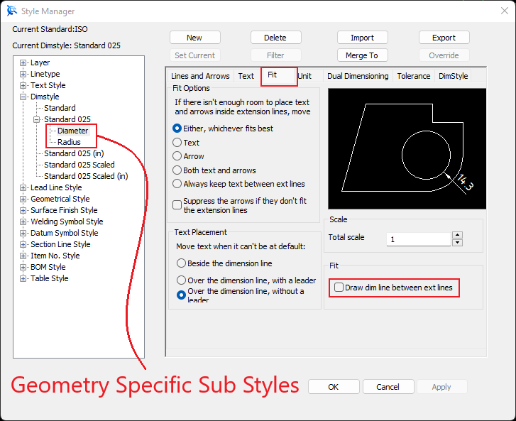
Within the Dimension Styles of CAXA DRAFT it's possible to create "Dimension Type Specific Sub Styles". In the attached video I have created a sub style for Diameter and another sub style for Radius. In each of these sub styles I've turned off the "Dimension Line Between Extension Lines". When the parent Dimension Style (Standard 025) is set to current, those sub styles within it will be applied to their specific geometry. This eliminates the need for manually toggling off the Dimension Line afterwards, when dimensioning small circles and arcs. Malcolm CAXA DRAFT - Dimension Styles - Geometry Specific Sub Styles.mp4
-
Hi Kim, CAXA DRAFT does have Dimscale (Dimension Scale), and it is very easy to access (not too many clicks for your fingers). See the attached video if you're interested. In my experience of helping new users, it is a myth that CAXA DRAFT is more difficult to learn and use than ICD. Unfortunately, it is just poorly configured by default, and isn't promoted by IRONCAD and Resellers (for reasons that I don't understand). Most users should be encouraged to use CAXA DRAFT rather than ICD (for many reasons). Malcolm CAXA DRAFT - Dimscale.mp4
-
Sweep along two guide curves - IRONCAD 2022
Malcolm Crowe replied to emil.rindell's topic in General Discussion
Hi Emil, Attached is an example of how to achieve a similar result to what you're after. This uses the Surface Sweep tool with two guide curves, but in a different way to what you were perhaps attempting (and expecting). I've created this as a Structured Part so that everything remains associated when driving the size and shape. Let me know if this helps. Malcolm Sweep Along Two Guide Curves.mp4 Sweep Along Two Guide Curves.ics -
At the request of Harley, attached is a video providing more detail regarding how the various construction sketches are constrained to each other. I've also attached a video showing how to position other parts to this part. Malcolm Structured Parts - Flexible Ribbed Hose - Using Surface Loft - Sketches.mp4 Structured Parts - Flexible Ribbed Hose - Using Surface Loft - Positioning.mp4
-
Structured mode - position dragged in parts and positioning
Malcolm Crowe replied to HDEAR's topic in General Discussion
Good spotting Harley, The problem you're having is because the geometry of this hose has been created as a loft, which doesn’t have a “center” that the TriBall can snap to. Attachment Points could be added to the center of both ends (on the Total Path), or you can simply make the 3D curve visible for positioning purposes and then hide again when you're done. This is shown in the attached video. Malcolm Structured Parts - Flexible Ribbed Hose - Using Surface Loft - Positioning.mp4- 2 replies
-
- 2
-

-
- positioning
- mode
- (and 1 more)