


Malcolm Crowe
-
Posts
1,760 -
Joined
-
Last visited
Content Type
Profiles
Forums
Blogs
Downloads
Articles
Gallery
Everything posted by Malcolm Crowe
-
Hi Kim, As you have already said, IRONCAD accesses files from many different locations, including "Program Files", "User AppData" and "User Documents". None of these locations are helpful in a multi-user working environment, where its advantageous to share common configuration and data files. Therefore, wherever possible we direct IRONCAD and CAXA to a Custom Shared Folder Structure located on SharePoint. This includes folders for "copies" of customized AppData files that need to be copied to "Program Files" and "User AppData" of each local computer. I've just completed updating our inhouse documentation regarding these "Files and Paths", and I've attached these here for the benefit of other users. Malcolm IRONCAD DRAFT - Files and Paths - 20230729.pdf IRONCAD - Files and Paths - 20230729.pdf
-
 Thanks Peter, your input is appreciated. I've attached a video here demonstrating the "Object User Coordinate System" as well. Malcolm CAXA - Object User Coordinate Systems (OCS).mp4
 -
I'm supportive of the current behavior (but also have no objection to another option for users). The current behavior makes sense when you understand the intent. This behavior is also consistent with drag-and-drop from catalogs. Malcolm
-
Hi Gigi, I downloaded your ICS file, but I was unable to open it. So, based on what you've described above along with your previous post, I've tried to demonstrate in the attached video what I think you're trying to achieve. To solve these types of problems we typically use "Layout Sketches", so that is what I'm demonstrating here. My apologies if I have completely misunderstood what you're trying to achieve, but perhaps this will still give you some other ideas that you can apply elsewhere. Malcolm Sheet Metal Layout Sketch - 20230117.mp4 Sheet Metal Layout Sketch - 20230117.ics
-
Hi Gigi, This may not help you as it isn't applicable to IRONCAD DRAWING (ICD), but the way this would be done in CAXA DRAFT (and other CAD systems) is to create a "User Coordinate System" (UCS) that is aligned with the direction that you want to dimension. While that UCS is active, any geometry or annotations placed would be aligned with that UCS. The link below is to a post demonstrating this in CAXA DRAFT. Malcolm
-
Within the 3D Scene, users have the ability to create "Local Coordinate Systems" alongside the default "World Coordinate System". Within CAXA DRAFT there is a similar capability, where users can create "User Coordinate Systems" alongside the default "World Coordinate System". Attached is a video demonstrating some examples of how "User Coordinate Systems" can be used, for creating geometry and annotations aligned to other geometry. Malcolm CAXA - User Coordinate Systems (UCS).mp4
-
Adjust gap between center line and annotation
Malcolm Crowe replied to LEE MENG CHE's topic in General Discussion
Hi Lee, I'm assuming that you are referring to the size of the "Mask" that is included with all text in CAXA DRAFT, for the purpose of "Hiding" objects behind it. See the attached video. Unlike some other CAD software, CAXA DRAFT does not provide the option to size the "Mask" relative to the text, for creating a larger gap (offset) around it. Malcolm CAXA DRAFT - Text Hide (Mask).mp4 -
Considering replacing AutoCAD with ironcad...
Malcolm Crowe replied to keeganhennis's topic in General Discussion
It never occurred to me (but should have) that you were referring to Visibility States within Dynamic Blocks (rather than Layer States). I am familiar with this, as our other software (BRICSCAD BIM) has this capability. As I understand it, only AUTOCAD is able to create "Dynamic Blocks" as their implementation is patented. Other DWG Editors that are based on SDKs of the Open Design Alliance (ODA) can open and edit "Dynamic Blocks" but just aren't permitted to create them. As a result, other DWG Editors create "Parametric Blocks" that can offer similar functionality to "Dynamic Blocks" (including Visibility States). My personal opinion is that BRICSCAD is the best alternative for AUTOCAD users looking for comparable functionality and compatibility. This includes powerful "Parametric Blocks". BRICSCAD can even convert existing "Dynamic Blocks" to their own "Parametric Blocks", so that users can utilize existing libraries. Malcolm -
Considering replacing AutoCAD with ironcad...
Malcolm Crowe replied to keeganhennis's topic in General Discussion
Hi keeganhennis, To begin with, as a CAD user that has experience with different CAD software, I wish you well as you evaluate what CAD software best fits your needs. Firstly, note that IRONCAD has a separate environment for 3D modelling (with its own *.ics file format) and two separate environments for 2D Drawing / Drafting (with their own *.icd and *.exb file formats). So, this is quite different to AUTOCAD where you will be used to doing both 3D and 2D within a single *.dwg file. In answer to your initial questions, I offer the following answers: 1a. There are 2 options available for 2D Drawing / Drafting in IRONCAD. Neither IRONCAD DRAWING (ICD) or IRONCAD DRAFT (CAXA DRAFT) offer Dynamic Blocks or Visibility States. IRONCAD DRAFT (CAXA DRAFT) does offer the creation of parametric symbols (blocks), which you can drag-and-drop from a Custom Library into your drawing and sized by dialog box (these don't have handles like Dynamic Blocks). 1b. Regarding Visibility States, the 3D Scene of IRONCAD offers "Configurations" which allow users to control the visibility of 3D Features, Parts and Assemblies within the 3D Scene. These same "Configurations" are also used for controlling what is displayed within Generated Views in IRONCAD DRAWING (ICD) and IRONCAD DRAFT (CAXA DRAFT). However, within the Layers Manager of the 2D Environments there isn't the ability to create "Visibility States" of Layers, in the same way that you're used to. So, visibility is controlled in a different way. 2. The 3D tools are available within the 3D Scene. The 2D tools are available within the 2D Drawing / Drafting environments of IRONCAD DRAWING (ICD) and IRONCAD DRAFT (CAXA DRAFT). Of these 2D options, IRONCAD DRAFT (CAXA DRAFT) has the more comprehensive 2D Modelling and Drafting tools (and Model Space) that you're used to from AUTOCAD. 3. Yes, Boolean operations are available for solids within the 3D Scene. 4. Yes, Wipeout frames are available within IRONCAD DRAFT (CAXA DRAFT), but not within IRONCAD DRAWING (ICD). 5. Yes, you can customize the User Interface of both the 3D and 2D Environments according to the "Classic" toolbar style if you prefer. 6. Yes, you can export 3D solids from the 3D Scene in the STL file format for 3D printing. 7. You can create and render your 3D models within the 3D Scene. There is a simple renderer included, however, depending on what you need you might need a more advanced 3rd party renderer as well to achieve better results. The 2D Drawings can be produced in IRONCAD DRAFT (CAXA DRAFT) using Generated Views from the 3D Scene, or by creating 2D Models in Model Space and then using View Ports within your layouts. 8. Yes, perpetual license. This normally includes the first 12 months of updates, after which you can choose whether to pay the annual software subscription for additional updates. I hope that helps. Malcolm -
Combining Assembly and Part Levels (CAXA)
Malcolm Crowe replied to Malcolm Crowe's topic in Tips and Tricks
Hi Kim, The setting you're after is shown in the attached image. That is, Options/3D Interface/BOM and Others/Default Configuration. Malcolm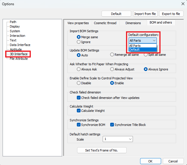
-
Hi Kim, You haven't followed the "Tip" video correctly. It is important that the reference files used for the 3D BOM are the same files used for Generating the Views. Try the following: 1. Externally save the Assembly as 4A260 BRACKET LOADING. This is the primary file that the following steps 2 and 3 will be referencing. 2. Start a new scene and insert the Assembly file created above. Save this file as 4A260 BRACKET LOADING - BOM Level 2 (Sub-Assemblies) 3. Start a new scene and insert the Assembly file created in step 1. Save this file as 4A260 BRACKET LOADING - BOM Level 3 (Parts) 4. Within your CAXA drawing, generating views using the new files from steps 2 and 3. 5. Within your CAXA drawing, insert a 3D BOM referencing the file from step 2, and set the Import Level to level 2 (sub-assemblies). 6. Within your CAXA drawing, insert a 3D BOM referencing the file from step 3, and set the Import Level to level 3 (parts). The rest of the details as per the video in the "Tip" forum post. Malcolm
-
The first thing that I do after installing a new version of IRONCAD, is to create (save) "Default" configuration files for: 1. User Interface 2. System Options This is demonstrated in the attached video for both IRONCAD and CAXA DRAFT. After creating these "Default" configuration files, I then customize the "User Interface" and "System Options" within IRONCAD and CAXA DRAFT according to my needs and preferences, before repeating the process to create (save) "Custom" configuration files. The reason for creating these "Default" files first is to enable me to restore IRONCAD and CAXA DRAFT to their original default configuration, if problems arise during customization, or if I want to compare my final custom configuration with the default. Malcolm IRONCAD and CAXA - Saving Default Configuration Files.mp4
-
Hi Kim, The link below is to a post regarding combining Assembly and Part Levels within a BOM in CAXA DRAFT. This may help you achieve what you want, or at least give you a better idea of what is currently possible. Malcolm
-
Transparent of that has transparency parts in Drawings?
Malcolm Crowe replied to Bertrand Kim's topic in General Discussion
Hi Kim, Attached is a video of a workaround for CAXA DRAFT to achieve the same end result that you want. It involves the following steps: 1. Creating a 2D Block of the Transparent Part(s) at a scale of 1:1 (generate view of the transparent parts, explode the view, create block). 2. Inserting that 2D Block within the Generated View. 3. Hiding the original 3D Transparent Part (using the Views Tree). Being a workaround, this isn't ideal. But it gets the job done when required. Ideally, it would be better if users could right-click on a part in the "Views Tree" and select "Make Part Transparent (...........)". Where this selection then toggled the "Hide" and "Not Hide" options of the Part (Blocks) within the Generated Views. I imagine that this wouldn't be too difficult to do in CAXA, as the functionality is already there (but disabled for generated views). Malcolm CAXA - Transparent Parts Workaround.mp4
-
For those interested, attached is a document describing the 3 different modelling modes within IRONCAD (as listed below), and how these relate to the common modelling approaches used for 3D modelling (that is, "Direct Face Modelling" and "Feature Based Modelling"). 1. Innovative Part Modelling - Offers Greater Freedom (best suited for simple single bodied models) 2. Structured Part Modelling - Offers Greater Functionality (best suited for complex multi-bodied models) 3. Sheet Metal Modelling - Sheet Metal Specific It is a common mistake among IRONCAD Users and Resellers that "Innovative Part Modelling" is somehow better than "Structured Part Modelling". That simply isn't the case. There are many parts that simply cannot be modelled using "Innovative Part Modelling" (multi-bodied parts being the obvious example). The strength of IRONCAD is that you can choose the modelling mode that is best suited for what you're trying to model. The link below shows some examples of where "Structured Part Modelling" has been used. The models themselves are not attached though. Malcolm IRONCAD - Modelling Modes - 20220912.pdf
-
Hi Kim, Adding to what Kevin pointed out, unless you're using punch tools where you want the tool centerlines displayed, I recommended that you deselect "Sheet metal tool centerlines" within Options / Properties List. See the attached image. Malcolm

-
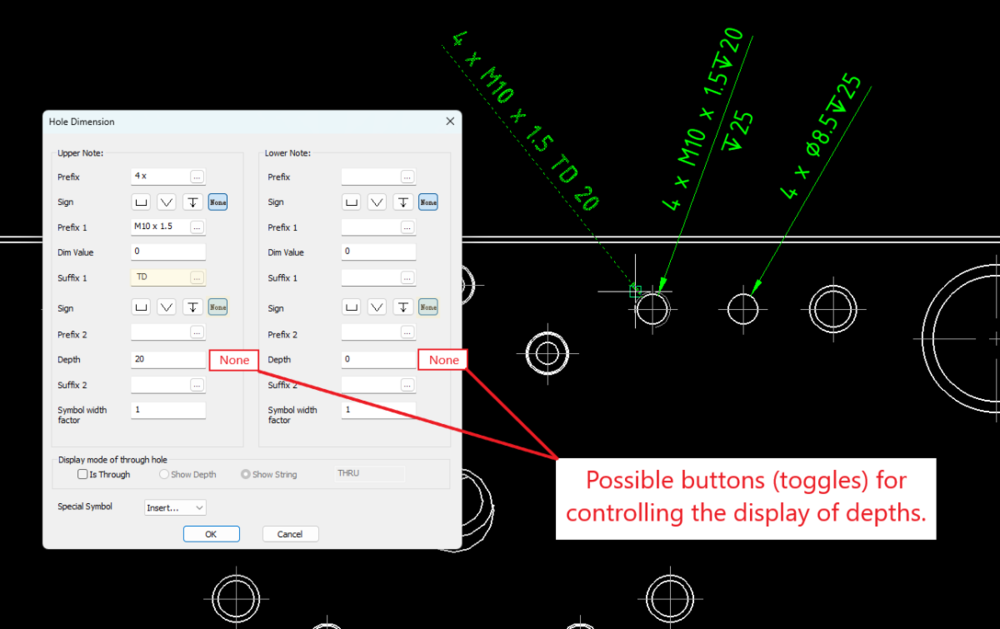
Hi Kim, If I understand what you want correctly, you want the ability to turn off the depth of the drilled hole (the lower note). I think it would be good to have a button (toggle) next to the depth of both the Upper and Lower notes, for controlling the display of these, as it isn't always wanted (such as when depths are already dimensioned in Section Views). See the attached image. Apart from having to delete the Lower depth every time you place a hole dimension, CAXA will remember the other settings that you want in the Upper Note. In the attached video and image, I've used the Upper Suffix 1 to add your "TD". So, maybe this will help you a little bit. Malcolm CAXA 2022 - Hole Dimension - Unable to Turn Off Depths.mp4
-
Hi Peter, For your reference, you might find this post helpful as well regarding applying color to Part, Intellishape and Face levels. Malcolm
-
Within the Right-Click Menu of the Title Block is a useful tool named "Set 3D Info". This opens a Dialog Box that is automatically populated by the last inserted View or BOM. But more importantly, it enables users to update the Title Block (if necessary following property changes in the 3D Scene), or to select a specific Configuration, Assembly or Part (within the 3D Scene) to be used for populating the Title Block. This is demonstrated in the attached video. Malcolm CAXA - Title Block - Set 3D Info.mp4


-
The equivalent tool in CAXA DRAFT is named "Break BOM". This is located within the Paper Tab of the Ribbon Menu, as shown in the attached image. Take careful note of the options within the "Instance Menu" at the bottom left of the screen. A video is also attached demonstrating how to use this to break and recombine BOMs. Malcolm CAXA - BOM - Break BOM (Split).mp4
.thumb.png.6b5277b22402406815efa49fc477a98a.png)
- 1 reply
-
- 1
-

-
Hi Kim, I've just been around long enough to remember when that capability was introduced. Malcolm
-
There is a trick to setting the default behavior for the Hole Dimension tool. Instead of left-clicking to place the dimension, right-click to open the dialog box. Any changes that you make here will be treated as the defaults for future dimensions that you place. Again, the right-click to open the dialog box is the trick. This is demonstrated in the attached video. Malcolm CAXA - Hole Dimension - Setting Default Options.mp4
-
CAXA - Can I change the default Welding Symbol's colour?
Malcolm Crowe replied to Bertrand Kim's topic in General Discussion
As a bit of a tip, we also always place our "Weld Beads" inside the Generated View (using Block Editing) so that the Weld Beads move and scale with the view. Malcolm -
CAXA - Can I change the default Welding Symbol's colour?
Malcolm Crowe replied to Bertrand Kim's topic in General Discussion
Hi Kim, What you're referring to is the "Weld Bead" and not the "Weld Symbol". The "Welding Symbol Style" above has nothing to do with the Attributes (Properties) of the "Weld Bead". There currently isn't any control for users to set the layer and color. CAXA think they know better so have nominated the layer and color for us (which we then edit after placing). While this isn't ideal, it also isn't difficult to do. The link below is to a forum post 3 years ago when I raised the same questions as you. Malcolm -
User Interface - Positioning of the Instance Menu (CAXA)
Malcolm Crowe replied to Malcolm Crowe's topic in Tips and Tricks
Hi Peter, Not that I'm aware of. In the case of the current Offset Line tool, there are a couple of main options, which are very fast depending on what you're doing (see the attached video). While I don't use the Offset Line tool that often, I do often use the Parallel Tool (which behaves a little differently). If the Offset Line tool could behave in a similar way to the Parallel Line tool when using the Across or Through Point option, then I think that would be helpful. Malcolm CAXA DRAFT 2022 - Offset Line.mp4


.png.df6749964eabc82807433660607a3bbd.png)