Malcolm Crowe
-
Posts
1,760 -
Joined
-
Last visited
Content Type
Profiles
Forums
Blogs
Downloads
Articles
Gallery
Everything posted by Malcolm Crowe
-
 Hi Kim, The same problem exists in my testing of IC2023 SP1. The problem is that the preview of the "loop" (contour) created for the Broken-Out Section isn't scaled with the View. If the View has a large scale (100:1 for example), then when editing the "loop" that you need to click within will be very small (at a scale of 1:100) compared to the View. That is very small. If the View has a small scale (1:50 for example), then when editing the "loop" that you need to click within will be very large (at a scale of 50:1). Malcolm
 -
Within a "Structured Frame" (or any multi-bodied Structured Part) it isn't possible to directly suppress a "Body" (like we can with "Features"). However, it is possible to add "Delete Body Features", that can then be suppressed and unsuppressed. The end result being the same as suppressing the Bodies. This is demonstrated in the attached video. Malcolm Structured Frames - Suppressing Bodies (Members).mp4
- 1 reply
-
- 2
-

-
Structured Frames - Adding Custom Shapes and Sizing Data
Malcolm Crowe replied to Malcolm Crowe's topic in Tips and Tricks
Thanks Harley, This was prompted by your post regarding Weldments back on the 5th March. I chose not to reply back then, as I thought a more compressive explanation would be more helpful to you (and others). An important part of understanding Structured Frames is understanding how BOMs within 2D Drawings reference them (as this is different to regular Parts and Assemblies). This was the reason for the other post regarding "Bodies" displayed in BOMs. This all required some preparation on my part (along with the supporting reference document). Malcolm -
Within the "Structured Parts" tab of the Ribbon Bar in IRONCAD 2023, within the "Structured Frame" panel, a new tool has been added named "Add Custom Structured Frame". This newly added tool enables users to add their own Custom Shapes based on 2D Sketches and Size Data (which can be entered directly or imported from an Excel Spreadsheet). In the attached video I have tried to demonstrate the process involved. Pages 4 - 6 of the attached reference document also covers this. Malcolm Structured Frames - Adding Custom Shapes and Sizing Data.mp4 IRONCAD - Structured Frames - 20230312.pdf
-
Within the "Structured Parts" tab of the Ribbon Bar in IRONCAD 2023 is a panel named "Structured Frames". This was previously named "Steel Frame" and is similar to "Weldments" within SOLIDWORKS. Structured Frame "Features" are inserted into Structured Parts, and within these "Features" are "Bodies" (Frame Members). The purpose of this post is to make users aware of the influence Structured Frames have on the Bill of Materials (BOM). Normally, the BOM references the "Part Level Properties" of a Part or the "Assembly Level Properties" of an Assembly. As soon as a "Structured Frame Feature" is inserted into a Structured Part, the BOM stops referencing the "Part Level Properties" of that Parent Part, and instead starts referencing the "Body Level Properties" of the Frame Members. As a result, the Parent Structured Part is no longer treated as a Part (or Assembly), but as an invisible Construction Object or Container (for lack of a better word). In the attached video I have tried to demonstrate this. Page 3 of the attached reference document also covers this. Malcolm Structured Frames - Bodies (Members) Displayed in BOM.mp4 IRONCAD - Structured Frames - 20230312.pdf
-
Image attached. I hope that this is clear enough.

-
Could I edit CAXA's default layers?
Malcolm Crowe replied to Bertrand Kim's topic in General Discussion
Thanks tgjang, I share because there aren't useful resources available for CAXA, and there is very limited understanding within the IRONCAD Community. Even though CAXA offers a lot more for users than IRONCAD DRAWING (ICD) ever could. CAXA has so much potential in the CAD market, but IRONCAD appears blind to it; so development resources have been used elsewhere. Malcolm -
Dimension input issues for 2023 version CAXA
Malcolm Crowe replied to YEO's topic in General Discussion
Thanks for the update. I think your English is very good. Malcolm -
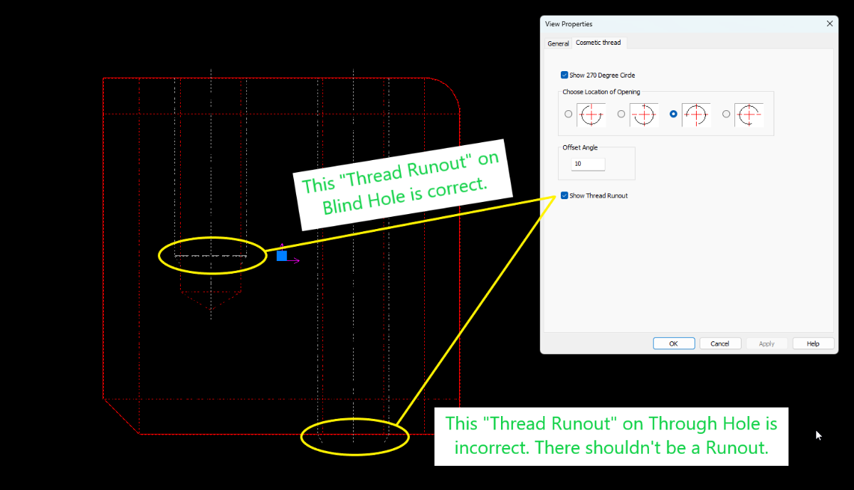
@IronKevin Please log this "Cosmetic Thread - Runout Showing on Through Holes" as a bug. Thanks.
-
Dimension input issues for 2023 version CAXA
Malcolm Crowe replied to YEO's topic in General Discussion
Hi YEO, For your comparison, attached are the settings that we use for Object Snap. Along with exporting our settings, we also take snapshots like this after configuring a new release. Malcolm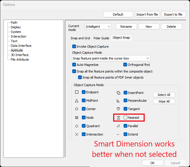
-
Hi YEO, I never use the "Thread Runout" option, so I've never noticed that problem with threaded holes thar extend through the part. This is a bug that needs to be logged by Support. Until it is fixed you can use the "Hide Lines" tool on the Ribbon Bar (3D Interface Tab) to hide those Thread Runout lines. Malcolm
-
Could I edit CAXA's default layers?
Malcolm Crowe replied to Bertrand Kim's topic in General Discussion
Hi Kim, You can't delete these 8 System Layers (as they are needed for Generating Views), but you can rename them to whatever you like. For example, CAXA's "Hidden Layer" doesn't related to Hidden Lines, but rather to objects that you don't want to print. Hidden Lines (within Generated Views) use CAXA's "Dash Layer". The attached document shows the layer names that we use for these 8 System Layers. However, we actually use a lot more layers than these basic 8. For example, we have separate Annotation Layers (and colours) based on Text Height, so that we can instantly identify different Text Heights throughout our drawings. Malcolm IRONCAD DRAFT - System Layers - 20231204.pdf -
Dimension input issues for 2023 version CAXA
Malcolm Crowe replied to YEO's topic in General Discussion
Hi YEO, When you select the "Smart Dimension" tool in the Ribbon Bar of CAXA, check the options in the bottom left of the screen. Ensure that "Base Dim" is selected. See the attached image and video. Please report back whether this was the issue or not. Thanks. Malcolm CAXA 2023 - Smart Dimension - Base Dim.mp4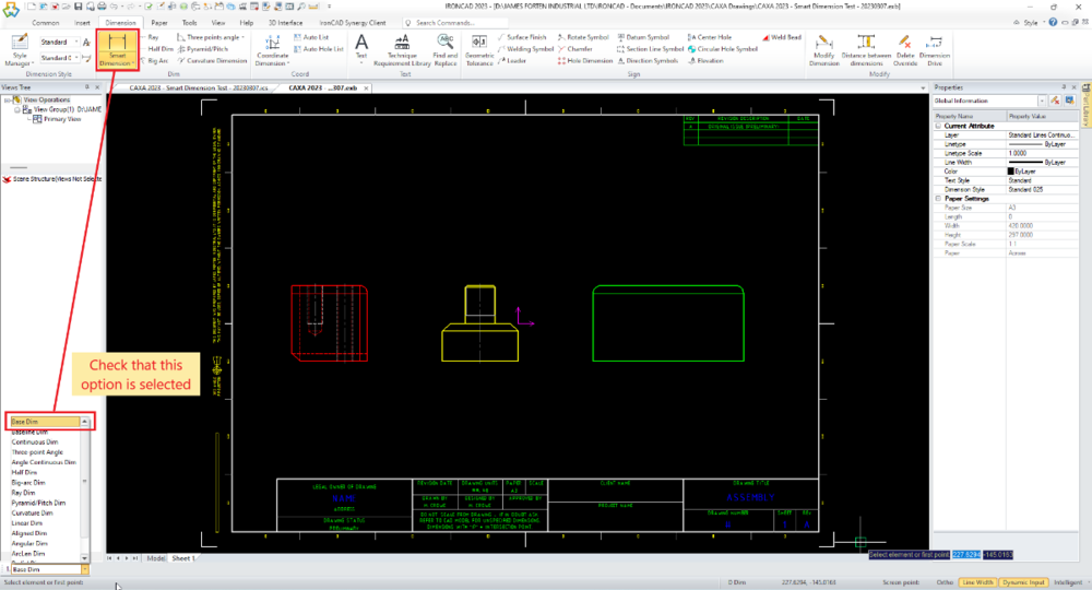
-
Questions about Steel Structures design.
Malcolm Crowe replied to tgjang's topic in General Discussion
Hi tgjang, You could model this completely using Innovative Parts or Structured Parts, but personally speaking I would use a combination of both. The Structured Frame feature (within Structured Parts) is well suited for Truss design, as Structured Frames aren't difficult to create and are incredibly fast to edit. This has been improved significantly in IC2023, with the introduction of Custom Structured Frames, and will hopefully develop further soon regarding the Frame Body Properties. Innovative Parts are well suited for the various Plates, Columns and Purlins. Malcolm- 2 replies
-
- 1
-

-
- structured part
- steel
- (and 2 more)
-
By default, all Parts and Assemblies within the 3D Scene should have "Include in BOM" selected (within the Properties Browser), as you normally want these to be included in a BOM. However, there are some exceptions, such as Construction Items (like Layout Sketches) and Reference Parts (like existing Parts or a Building etc...). For these items you would deselect "Include in BOM" when you create them. However, if the Referenced Parts have other 2D drawings referencing them (which might be the case with externally linked parts), DO NOT deselect "Include in BOM" for these Items, as doing so will affect those other drawings as well. In the attached video I demonstrate some options for excluding Referenced Items from the BOM in your 2D Drawing. This is specifically regarding CAXA DRAFT, but most of what is demonstrated is applicable to IRONCAD DRAWING (ICD) as well. Option 1: Within the CAXA BOM deselect the "Display" option. Option 2: Within the 3D Scene create a "Configuration" in which the Referenced Parts are "Suppressed". Then set the BOM to reference that specific "Configuration" while the Generated Views reference a different "Configuration". Option 3: Within the 3D Scene, place any "Reference Parts" within a specific "Referenced Parts" Assembly. Then in the Properties Browser of that Assembly select "Treat as Part", and then deselect "Include in BOM". Option 4: This is a variation of Option 3 above. Within the 3D Scene, place any "Reference Parts" within a specific "Referenced Parts" Assembly. Then in the Properties Browser of that Assembly select "Treat as Part", and leave "Include in BOM" selected. Then in the BOM of CAXA deselect "Display" for that one Item. This option allows the "Item Number" tool to be used for labelling these Referenced Parts within the drawing as well, without being listed in the BOM. Malcolm CAXA - BOM - Excluding Referenced Items.mp4
-
The attached video demonstrates how "Attachment Points" can be used for automatically sizing "End Plates" to match the geometry of the "Shape" that they are attached to. As the size and taper of the Shape changes, the parameter values are transferred (via the Attachment Points) to the End Plate, so that it can also change accordingly. Offset functionality (both inside and outside) can also be built into the End Plate, as can other features such as holes. Malcolm Parameters and Design Variations and Attachment Points - End Plates.mp4
-
CAXA-Another weird question regarding BOMS
Malcolm Crowe replied to HDEAR's topic in General Discussion
Hi Kim, I was just reviewing this old post and thought I'd question you about this statement. Perhaps I have misunderstood what you mean, but as far as I can see CAXA remembers the "Display" selections made within the BOM. See the attached video. Also, have you considered creating a configuration in the 3D Scene where the Fasteners are all suppressed, then have the BOM in CAXA refer to that specific configuration? Malcolm CAXA - BOM - Display of BOM Items - Selections Maintained.mp4 -
CAXA Extra sheets with frame and title block
Malcolm Crowe replied to emil.rindell's topic in General Discussion
Hi Emil, Regarding question 2, about the "Paper Scale" being set to 1:100 after importing the "Drawing Frame", I haven't seen this before. But it may be because the Paper Scale (within Paper Settings) was set to 1:100 when that particular "Drawing Frame" was originally defined. Malcolm -
CAXA Extra sheets with frame and title block
Malcolm Crowe replied to emil.rindell's topic in General Discussion
Hi Emil, Regarding question 1, CAXA will only list Drawing Frames that are applicable to the "Sheet Size" and "Sheet Orientation" selected within "Paper Settings". Because of this, before defining a new "Drawing Frame", it's important that the correct "Sheet Settings" are set, as these settings are going to be associated with the new "Drawing Frame" that you are about to define. This is covered in a previous post (linked below). There is other content within that post that also might be helpful. When setting up a new sheet I suggest using "Paper Settings" rather than using the direct "Import Frame" and "Import Title Block" tools. These direct tools are good if you know that the Paper Settings are already correct. Malcolm -
CAXA - Toggle TEXT SCREEN (F2 in AutoCAD)?
Malcolm Crowe replied to Bertrand Kim's topic in General Discussion
Hi Kim, I'm not aware of any keyboard command for showing and hiding the Command Line, but there is an "Auto Hide" option available which may help. See the attached video. Malcolm CAXA - Command Line - Auto Hide.mp4 -
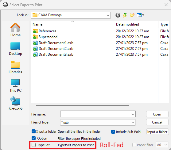
Hi Kim, What you're seeing is the output for a Roll-Fed printer (where the sheets are cut after printing). The "Print Tool" in CAXA can also create the individual sheets (layouts) as separate PDFs or combine the individual sheets into a single PDF; but there can be limitations based on the PDF printer being used. I use PDF24 for this purpose, as demonstrated in the following post. Follow carefully the steps I use in the video. In your case, when "Inserting File(s)", ensure that the "TypeSet" option is not selected. This option relates to Roll-Fed printing. See the attached image. Malcolm
-
Split a 3D curve with the same length
Malcolm Crowe replied to emil.rindell's topic in General Discussion
Attached is a video demonstrating a couple of options available for not displaying the Sweep Intellishape during 3D Curve Editing. 1. Innovative Part: Right-click in scene during editing, select "Show" then select "Hide Edited Intellishape" 2. Structured Part: By default the following Sweep Intellishape won't be displayed. Malcolm 3D Curve Editing - Not Displaying Sweep Intellishape.mp4 -
Externally Linked Files - Changing File Name and Path
Malcolm Crowe replied to Malcolm Crowe's topic in Tips and Tricks
Hi Kim, Thanks for contributing. It was good that you highlighted the "Do not process linked files" in the Save As dialog box. Regarding your video, because there is no audio (or text) explaining what you are doing, I found it a little difficult to follow. Malcolm -
There are advantages to working with externally linked files (as opposed to having all parts and assemblies within a single file), so understanding and having confidence in how externally linked files work is important. To help with that I've attached a couple of videos demonstrating how to create externally linked files from within a single scene file, and then how to change the name or path of those externally linked files. Malcolm IRONCAD - Externally Linked Files - Changing File Name and Path 1.mp4 IRONCAD - Externally Linked Files - Changing File Name and Path 2.mp4
-
What are the reserved words for IronCAD and CAXA Draft?
Malcolm Crowe replied to tgjang's topic in General Discussion
Yeah, that made me smile too. My wife, however, would just shake her head at that one (along with some of the other descriptions). I recently attached this document (and some others that might be of interest) to the "About Me" section of my Profile. Malcolm Malcolm Crowe - IronCAD Community