Malcolm Crowe
-
Posts
1,760 -
Joined
-
Last visited
Content Type
Profiles
Forums
Blogs
Downloads
Articles
Gallery
Everything posted by Malcolm Crowe
-

I would like to no how to read a AutoCAD 3D dwg file.
Malcolm Crowe replied to tgjang's topic in General Discussion
That's interesting about implementing 3D DWG import within the Native Translator. However, speaking as someone who collaborates with the DWG world a lot, I'm not convinced that this is the right approach to take for IRONCAD. DWG files that contain 3D models in Model Space will also contain 2D drawings within the Layout Space. My personal view has always been (and I have previously requested this) that CAXA DRAFT should be able to open 3D DWG files as well, along with any associated 2D Layouts. The SDKs regarding this capability are already available from the ODA, so CAXA / IRONCAD should be making use of them. Then there simply needs to be a link added between Model Space in CAXA DRAFT and IRONCAD's 3D Scene, so that the 3D model can be edited (and inserted into other scenes). By doing it this way you can potentially edit DWG 3D models in IRONCAD and maintain the associated 2D layouts (that are looking at the model in Model Space). If you do it any other way (such as is being considered) you will limit the potential interoperability. If you want to import 3D models from a DWG file into IRONCAD, then you currently need to export the "Solids" from the DWG file using the included "ACISOUT" command (or an exporting utility). Then you can import the ACIS solids into the IRONCAD Scene. Malcolm -
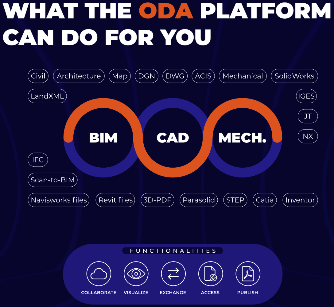
Hi Kim, It is part of the User Interface Style that I prefer to use for CAXA and IRONCAD. That is, "2010 Silver" that you can select in the top right corner. See the attached image. Malcolm
-
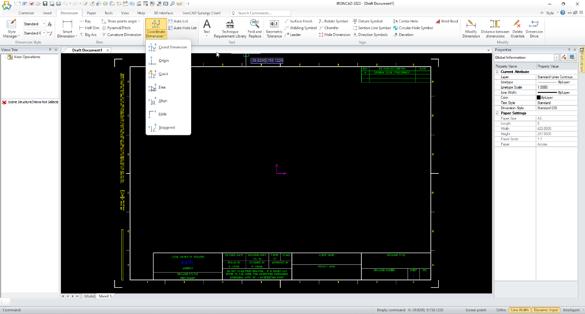
Hi Lee, The video above demonstrates Coordinate Dimensioning. CAXA has different Coordinate Dimensioning options available. See the attached image. When using, take careful note of the options and instructions at the bottom left corner of the screen. The process typically starts with selecting the "Origin", followed by the "Mark Points" (which will include the origin as well if you want to display "0" position). Malcolm

-
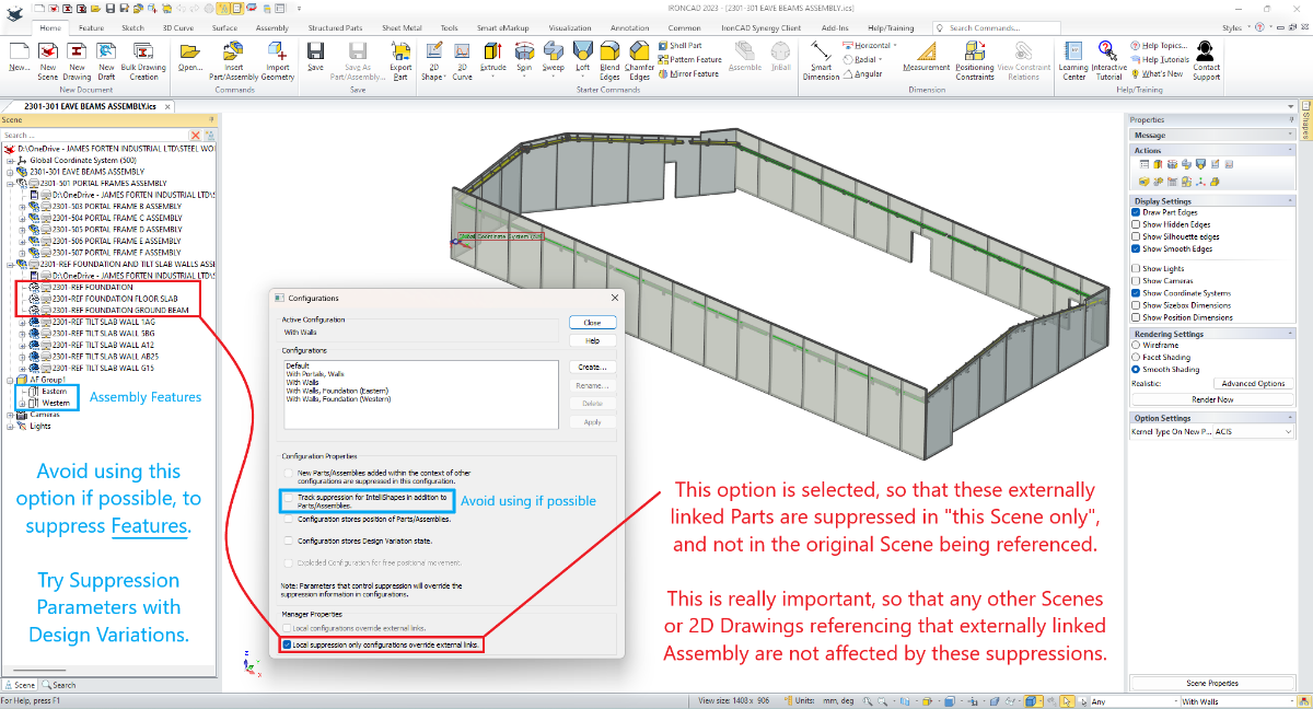
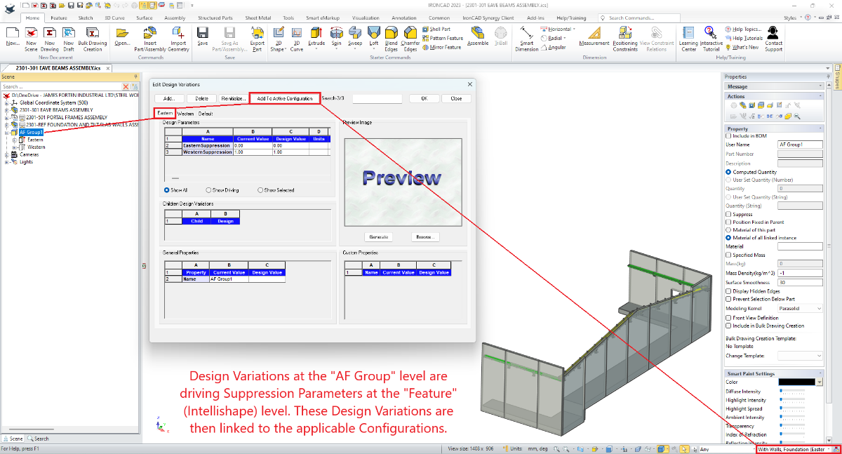
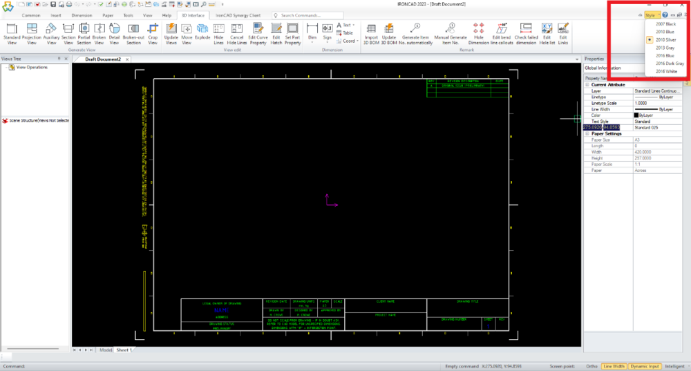
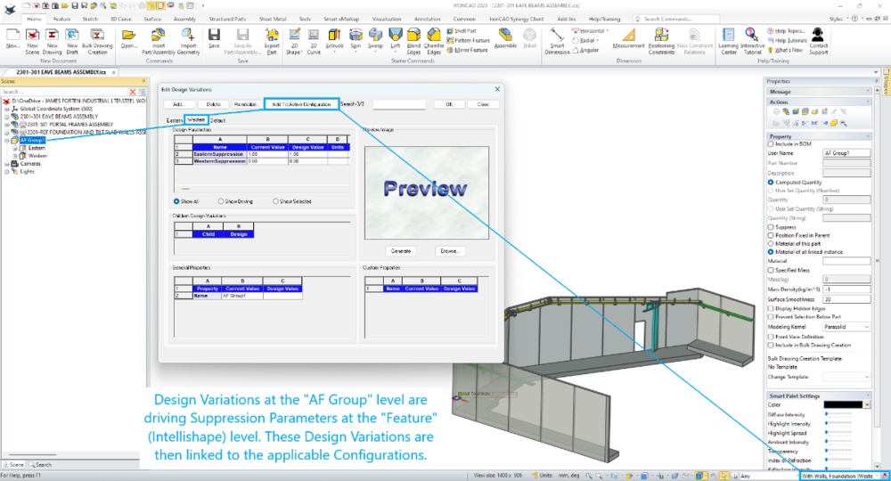
When a "Cut" Feature (Shape) is dropped onto a Part or Assembly using the Right Mouse Button, there is the option to apply this as an "Assembly Feature". How this is different from a regular Feature (Shape) is that it is applied within the current Scene only. If the Part or Assembly onto which this was dropped is externally linked, then this Feature won't appear within the original file (which is a good thing). This makes Assembly Features useful for secondary Assembly operations (such as drilling), but also for Sectioning purposes (as the current Sectioning Tool has some limitations). Having created "Assembly Features", how can you then link the suppression and unsuppression of these "Features" with Configurations? When creating new Configurations there is an option to "Track suppression of Intellishapes ....". If this option is selected, then the Configuration can control the suppression and unsuppression of "Assembly Features". However, this option should be avoided, if possible, especially for large assemblies. Instead, "Design Variations" can be created for the "Assembly Feature Group" (which behaves similar to a Part). These "Design Variations" can then control "Suppression Parameters" within the "Assembly Features" (for toggling them on and off). Not only that, but these Design Variations can then be associated with Configurations, without needing "Track suppression of Intellishapes ......". This is demonstrated in the attached video and images. Malcolm IRONCAD - Assembly Features - Controlling Suppression Using Design Variations.mp4

-
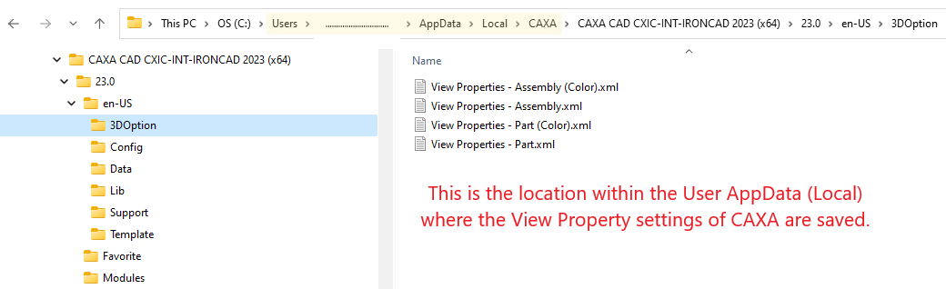
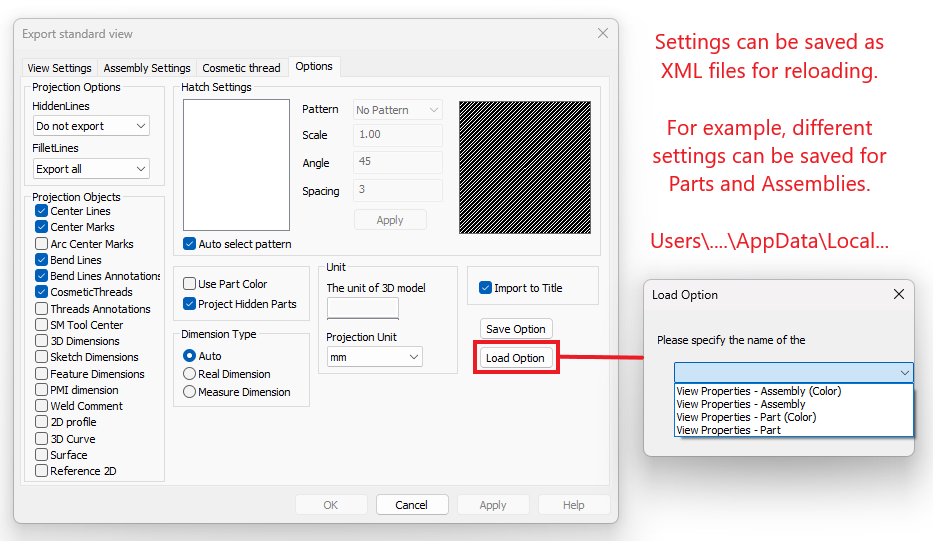
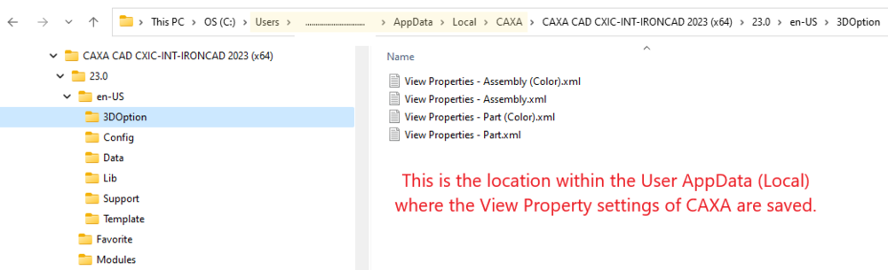
Adding to what Kim has mentioned above, when Generating Views, users can also "Load" previously saved View Property settings. See the attached images. Malcolm
-
Within CAXA DRAFT, when you need to Generate Views of large assemblies that contain thousands of fasteners, turn off the Centerlines and Cosmetic Threads within the View Properties. This will greatly reduce the number of lines that CAXA needs to generate, and therefore improve the performance when regenerating the View. See the attached video. Malcolm CAXA - Generated Views - Turning Off Centerlines and Cosmetic Threads.mp4
-
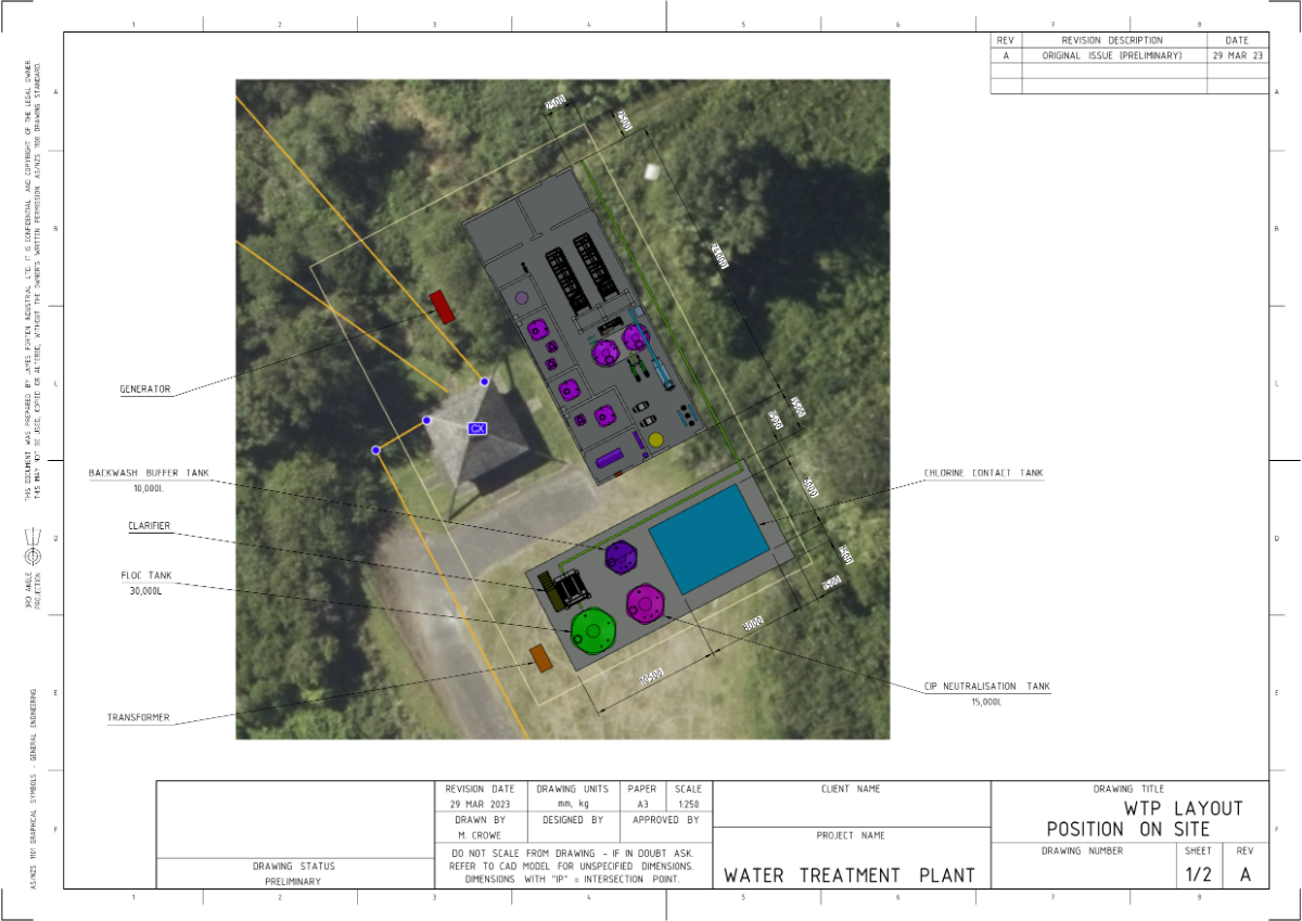
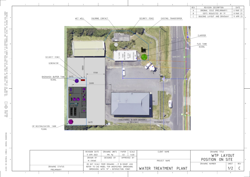
Sometimes we need to combine images (such as aerial photos) with 2D Geometry and Generated Views within our 2D Drawings. Attached are a couple of examples of these types of drawings. These examples were prepared in CAXA DRAFT for preliminary site layout discussions with clients. After inserting images in CAXA DRAFT, scale the image until a known distance between 2 points is equal to a scale of 1:1. That is, if you know that the distance of an existing structure or boundary is 25m, then scale the inserted image until those points measure 25m within CAXA DRAFT (using the "Distance" tool). Then create a "Block" that includes that image and any 2D Geometry that you want to add. For example, if you want to be able to dimension to an existing structure or boundary then draw some lines (2D geometry) over those areas so that you can reference them later. Having created the "Block" at a scale of 1:1, now scale the "Block" within the Properties Browser so that it fits within the drawing. This is the same process used for scaling Generated Views. Then when you insert a Generated View into the drawing (on top of the "Block"), set the scale of that Generated View to the same as the "Block" beneath it. The "Align" tool in CAXA can be used to perfectly position the Generated View relative to geometry added within the "Block". Then add dimensions and other annotations as required. Malcolm

-
For those users that don't use IC Mech, I recommend using the "Custom Hole" tool on the Ribbon Bar rather than the similar tool in the Tools Catalog, as you can easily create your own catalog of Custom Holes, for then dragging and dropping onto Parts as required. It's the quickest way to create drilled holes. See the attached demonstration video. Malcolm IRONCAD - Custom Holes - Create Custom Catalog.mp4
-
Hi YEO, In the attached video CAXA is correctly recognizing "Thru" holes that were created using the "Custom Hole" tool. So perhaps the problem is with IC Mech rather than with CAXA. Malcolm CAXA - Hole Dimension - Thru.mp4 Custom Hole Tool.ics Custom Hole Tool.exb
-
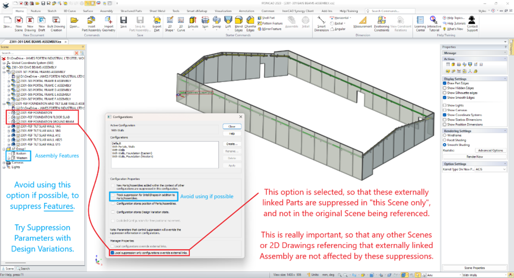
Hi tgjang, In the particular example above (and in the attached video) all of the Structural Steel components were modelled using Innovative Mode. However, the referenced Concrete Foundation and Tilt Slab Walls were modelled using Structured Mode. We always use Structured Mode for creating our layouts for referencing, as there will be a number of 2D Sketches (including the Architects Grid) that we need to be fully associated. And in this instance, the Concrete Foundation and Walls are separate "Bodies" within this Reference Layout. Our projects are seldom created using 100% Innovative Mode or Structured Mode, as both modes have their advantages (depending on the application). For example, for Structural Engineers involved during the design stage, using Structured Frames (rather than Innovative Parts) is actually more advantageous for them. During stress analysis calculations they work with Wireframe Models, to which they apply "Shape Profiles". The process is very similar to the process of creating Structured Frames, so it's a concept that is familiar to them. When the "Design Stage" is complete their basic "Structured Frame" can be added to by others (which will include Innovative Parts). So, whenever you're presenting IRONCAD as an alternative to SOLIDWORKS, INVENTOR etc..., I always recommend focusing primarily on IRONCAD's versatility (rather than ease of use, or Innovative Mode, or the TriBall, Catalogs, etc...), where IRONCAD users have the freedom to choose the modelling mode best suited for the application. The shapes required for Structural Engineering applications are very basic, so there is no benefit in having dual kernels for these. However, if you're doing Factory Layouts where you need to insert models from other sources (including facetted models which are common in architectural applications), then in my own personal experience the dual kernels have been beneficial. BRICSCAD BIM is truly versatile software as well, but in different areas to IRONCAD (although they do overlap). BRICSCAD BIM is specifically tailored for AEC (Architectural, Engineering and Construction) applications, and includes amazing Point Cloud and Civil Engineering tools as well (along with 3D modelling and 2D drafting capabilities that would surprise many IRONCAD users). If your client needs to create BIM models or collaborate with BIM models from others (whether IFC or REVIT), then BRICSCAD BIM is the way to go. Note that, BRICSCAD BIM can import 3D models created by other software (including IRONCAD) and automatically add the BIM data needed to turn it into a BIM model. That is something that we've done. So, your client could potentially use IRONCAD and BRICSCAD BIM side-by-side as we do (rather than either or). Malcolm STRUCTURED FRAME - Advantagous During Design Stage.mp4
-
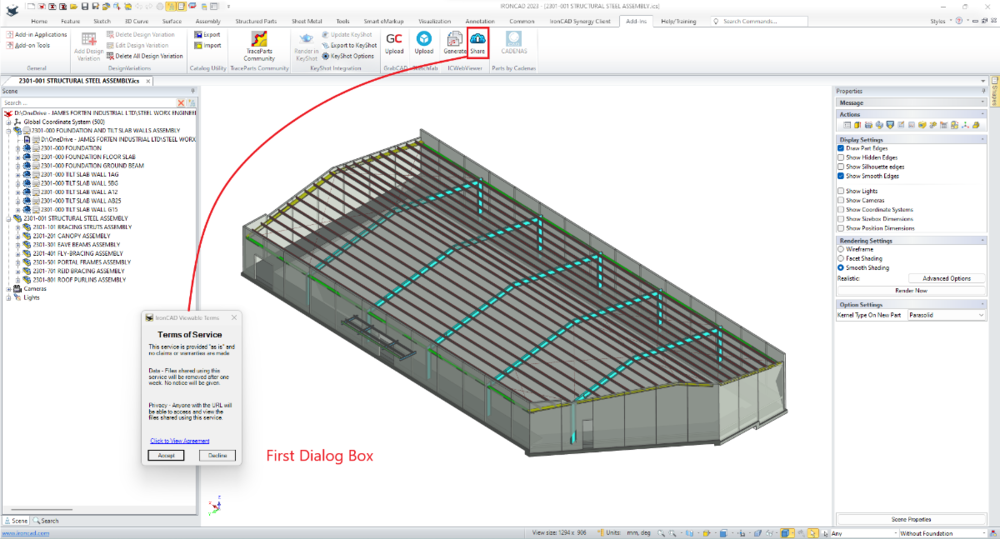
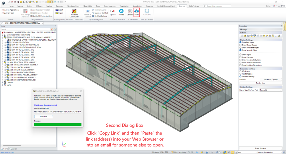
Since some users aren't familiar with this tool (and how useful it is), I thought I'd promote it again. Attached is an example of a typical demonstration video that I send clients (and others involved on the project), regarding how to use the Web Viewer after clicking on the link that I send them (via email). Malcolm IRONCAD - Web Viewer - 20230411.mp4
-
Structured part - can't get sketch to lock to 3 points
Malcolm Crowe replied to HDEAR's topic in General Discussion
Hi Harley, I was pleased when I saw your work-around, as it indicated a good level of understanding. Well done! Malcolm -
Structured flexi hose surface loft failure
Malcolm Crowe replied to HDEAR's topic in General Discussion
Hi Harley, The problem is with the direction of the "Arrow" after selecting the 4th arc. See the attached video. Malcolm IRONCAD - Surface Loft - Note Direction of Arrows.mp4 -
Structured part - can't get sketch to lock to 3 points
Malcolm Crowe replied to HDEAR's topic in General Discussion
Hi Harley, The attached video demonstrated 2 solutions to the problem selecting that 3rd point. It seems to have something to do with IRONCAD 2023 struggling to distinguish between the Point and the Circle in the other sketch. The first solution involves temporarily moving the Point off the Circle, so that it can be selected. The other solution involves temporarily making the Circle a "Construction" line (so that it isn't visible for selecting). Malcolm IRONCAD - 2D Sketch - Problem Selecting Point During Positioning.mp4 -
More problems with pattern in structured mode
Malcolm Crowe replied to HDEAR's topic in General Discussion
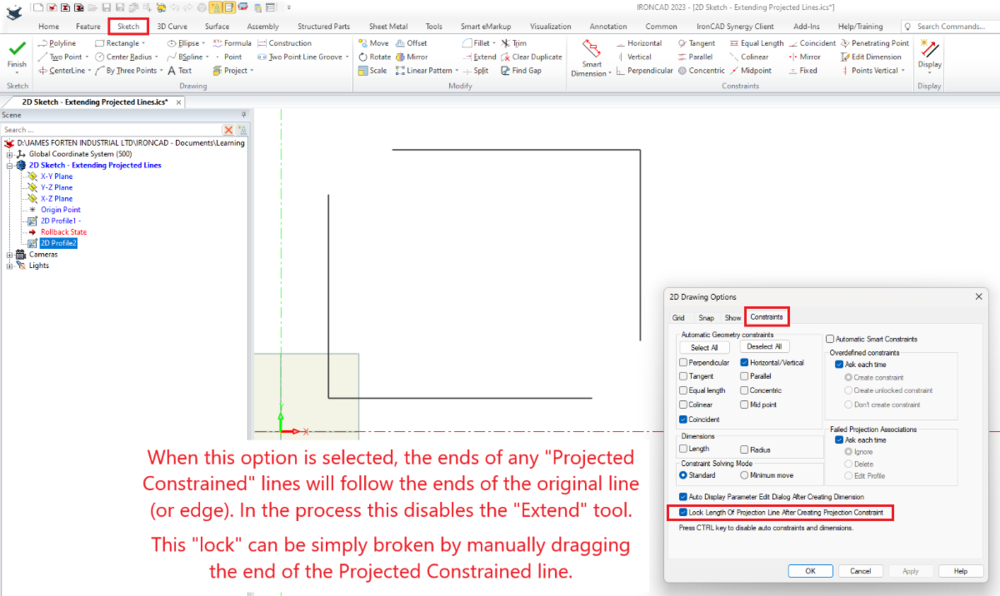
Hi Harley, Have a look at the attached images regarding "Lock Length of Projection Line After Creating Projection Constraint". There used to be a bug relating to this constraint, so in earlier versions (such as 2021) I used to have this option turned off. This constraint disables the "Extend" tool. The lock created by this constraint is simply broken by dragging the end of the line. Malcolm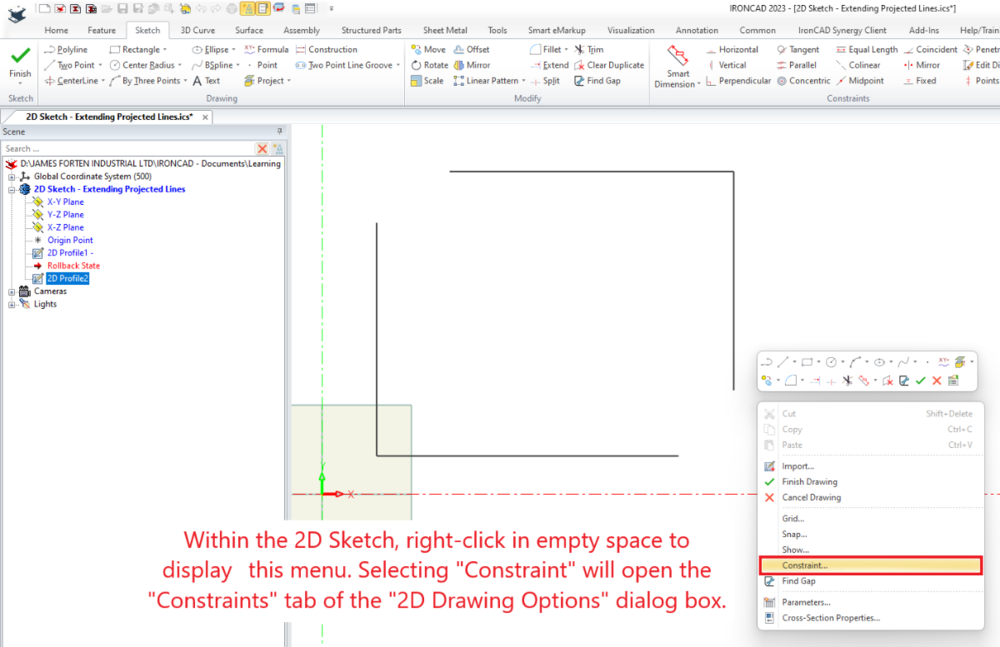
-
More problems with pattern in structured mode
Malcolm Crowe replied to HDEAR's topic in General Discussion
In the attached video I've added a "Surface" to the model, and then within the Extrude Feature Properties I've referenced that added "Surface" instead of the "Face" of the Body. The Feature Pattern then works correctly. So, the problem with Pattern Features in IC2023 seems to be regarding referencing "Faces" (which wasn't a problem previously). Malcolm Structured Parts - Pattern Feature - Extrude to Surface Problem.mp4 Structured Parts - Pattern Feature - Extrude to Surface Problem 2.ics -
More problems with pattern in structured mode
Malcolm Crowe replied to HDEAR's topic in General Discussion
I'm seeing the same problem in IC2023 regarding Feature Patterns where the original Feature is "Extruding to Surface". The first feature in the pattern is correct, but from the second onwards it's incorrect. Attached is a simplified model in which I have duplicated the problem in IC2023. I've tried using both the Edge Pattern and Linear Pattern, with both giving the same incorrect result. So, this is another issue within IC2023 regarding the Pattern Feature tool; yet I'm not aware of any changes being made to it, that could have contributed to these issues. @IronKevin please raise a bug report for this also. Malcolm Structured Parts - Pattern Feature - Extrude to Surface Problem.ics -
Pattern feature in structured part giving grief
Malcolm Crowe replied to HDEAR's topic in General Discussion
Hi Harley, I don't see any problem with what you have constructed in your model. This appears to be a bug in IC2023. In the attached video my original file works correctly, until I regenerate it, and update it to the current version (2023). Then this original file also displays the same problem that you are seeing in your model. @IronKevin please log this as a bug. I've also attached my original file, so that you can compare before and after regenerating. Malcolm Structured Parts - Pattern Feature (Bug).mp4 DOUBLE WALL TRAY.ics -
My original Engineering and Operational Management background was within high-speed Manufacturing Operations (24 hours per day, 6 days per week, and speeds up to 1,000 parts per minute). As a result, I have a very good understanding of the ingredients necessary to maximize “Productivity”. When consulting for new manufacturing clients, one of the typical questions that senior management ask is what new Plant and Machinery they need to invest in to “Increase Productivity”. More often than not, the missing ingredient that they need to invest in is “Training (Learning)” of their staff. The same is true regarding CAD productivity. The CAD software that you use is only one of the ingredients. The value of investing in expensive CAD software, add-ons, or upgrades, is greatly reduced if you don’t invest in learning how to use the capabilities they offer. You may as well have invested in far less expensive software better matched to your level of understanding and usage. So, if you've chosen to be in the design business, chosen to invest in the Hardware and the Software required, then “Choose to Invest in Training (Learning)” as well. You'll become a lot more "Productive" as a result. Malcolm
-
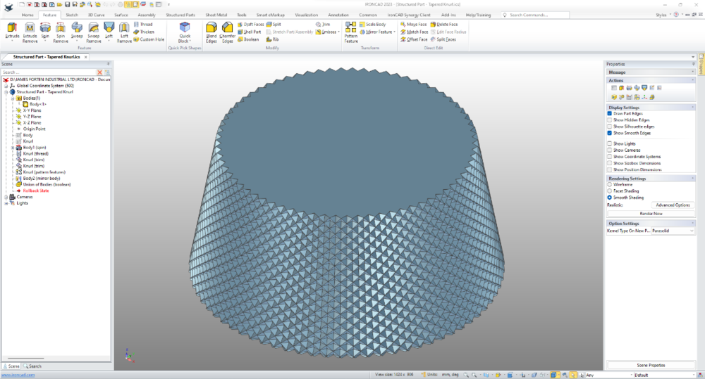
Hi Emil, I'm not sure if this is what you're after, but attached is a model of a Tapered Part with a "Tapered Knurl". This has been created as a Structured Part, making use of the "Thread Tool", the "Pattern Feature Tool" and the "Mirror Feature (Body) Tool". This is a very process intensive model, so you'll have to wait a while for the calculations to complete when editing features. The same process is used for "Parallel Knurls" on Cylindrical Parts. Malcolm Structured Part - Tapered Knurl.ics
-
Hi tgjang, Regarding the OPEN DESIGN ALLIANCE (ODA), I think that you must be referring to a different document of mine rather than the one attached here. I may be wrong, but my understanding is that ITC build their product around the ODA Platform (as is our other CAD software BRICSCAD). For anyone developing 2D/3D CAD software today, the ODA is the first place that they should start; to avoid wasting resources reinventing the wheel. Likewise, IRONCAD/CAXA should be making use as much as they can from the ODA as well. Malcolm

-
Hi Kim, I've attached some of our inhouse documents within the "About Me" section of my profile. That's about as close as you're going to get to finding various documents in one place from me (unless you're a client of ours). While I share a lot of our learnings with the IRONCAD Community, I don't share everything. Malcolm
-
Unlike other CAD software, IRONCAD is unique in that it uses both ACIS and PARASOLID geometric modelling kernels working in collaboration. For most users and applications this isn't important, but this feature provides greater versatility to IRONCAD, that isn't possible using a single kernel. For those interested in understanding the "Kernel Collaboration" within IRONCAD, attached is our own internal document. This includes a description along with practical examples of where manually switching kernels has solved real world modelling problems. Also attached is a video of our most recent example. This involved importing and converting of a SKETCHUP Faceted Model (also attached), followed by displaying with "Real Projection" within CAXA DRAFT. This particular example required using both ACIS and PARASOLID kernels to achieve the desired end result. Other users should feel free to add other examples here also. Malcolm IRONCAD - Dual Kernels - Facet Models (Real Projection).mp4 IRONCAD - Dual Geometric Modelling Kernels - 20230330.pdf AXION MSR 8300-8309 EMERGENCY SHOWER AND EYE WASH.skp
-
Request: Reordering of Design Variations
Malcolm Crowe replied to Malcolm Crowe's topic in General Discussion
Hi Nickul, I don't know about the status of reordering, but I also have a request in place regarding Excel importing and exporting. Ticket 12449. I've asked that this behaves in a similar way to the import and export function of the new "Custom Structured Frames", as I would like to be able to use the same Sketches and Size Data (Excel Spreadsheet) for creating both Structured Frames and regular Innovative and Structured Parts. Malcolm -
Hi Kim, My mistake. The Broken View problem regarding Scaled Views was fixed in IC2023. Malcolm