


Malcolm Crowe
-
Posts
1,760 -
Joined
-
Last visited
Content Type
Profiles
Forums
Blogs
Downloads
Articles
Gallery
Everything posted by Malcolm Crowe
-
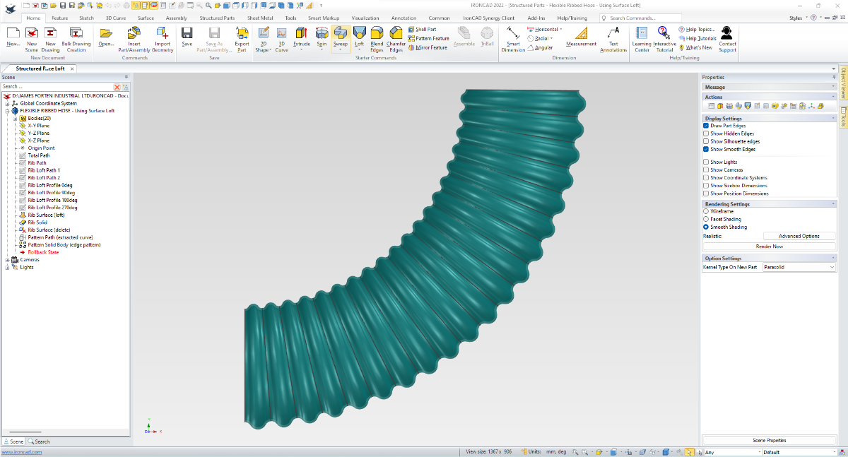
Prompted by a question from Harley, I've created another example of a Flexible Ribbed Hose. The original Rib is constructed as a "Lofted Surface", after which the "Thicken" tool is then used to create a solid Rib (from this surface) with the desired wall thickness. This solid Rib is then patterned along a 3D curve. The attached video provides an overview of the construction steps used, without going into all of the detail of creating and positioning of 2D sketches etc. This is a fully parametric model, so I've also included some Design Variations (45deg, 90deg, 135deg, 180deg bends) for demonstration purposes. Malcolm Structured Parts - Flexible Ribbed Hose - Using Surface Loft.mp4 Structured Parts - Flexible Ribbed Hose - Using Surface Loft.ics

-

Imported Point Clouds (PTS) - How to display color?
Malcolm Crowe replied to Malcolm Crowe's topic in General Discussion
The BRICSCAD Development Team have acknowledged the problem regarding exported PTS files (and opening in other applications such as IRONCAD), and that they will provide a fix. Malcolm -
Attached is a video demonstrating the difference between “Scene” and “Part” Front View Definitions; and also shows how to set the “Part” Front View Definition on folded and unfolded sheet metal parts, so that these can be referenced when Generating Views within CAXA DRAFT. Malcolm CAXA DRAFT - Front View Definition.mp4
-
Imported Point Clouds (PTS) - How to display color?
Malcolm Crowe replied to Malcolm Crowe's topic in General Discussion
As an update, I raised the issue with BRICSCAD as well, and below is the initial response from their local support. "To test, I generated a crop from a Pointcloud using BricsCAD in .PTS & .LAZ. Inspection of the .PTS file generated by BricsCAD indicates that it is using something other than RGB values to define colour. I don't know what these values relate to. Opening the .LAZ file didn't have any issues. Will need to find out from the development team what definitions they are using to create .PTS files." Malcolm -
Imported Point Clouds (PTS) - How to display color?
Malcolm Crowe replied to Malcolm Crowe's topic in General Discussion
Yes. RCP is a common Point Cloud format used by AUTODESK products. Malcolm -
Hi Cary, Yes I often use the "Faces to Intellishape" tool when editing holes, fillets (blends) and chamfers. It is a very useful tool! Malcolm
-
Imported Point Clouds (PTS) - How to display color?
Malcolm Crowe replied to Malcolm Crowe's topic in General Discussion
The original Point Cloud was an RCP file, that I opened and then cropped in BRICSCAD, before exporting as a PTS file for importing into IRONCAD. So maybe it has something to do with that process. Malcolm -
I've never liked this behavior myself regarding the delete key. I've had to retrain myself to only use the back space key when editing text in fields. Malcolm
-
Imported Point Clouds (PTS) - How to display color?
Malcolm Crowe replied to Malcolm Crowe's topic in General Discussion
Hi Cary, I've emailed a download link to support@ironcad.com Malcolm -
Attached are images of the same Point Cloud (PTS) imported into BRICSCAD BIM and IRONCAD. In BRICSCAD all of the colors of the original scan are displayed, however with IRONCAD all I see is black (monochrome). Is there a way to display the colors of imported Point Clouds in IRONCAD? For this reason (lack of color) we don't use IRONCAD at all when working with Point Clouds of buildings and associated plant and equipment. Instead we import our designs from IRONCAD into BRICSCAD, so that we can combine our designs with Point Clouds. Malcolm
inColor.thumb.png.e68515ce9d6b8b7e845bb3bb0bf6eb86.png)
inColor.thumb.png.9238db0df443c869f79e68c9dbd82b70.png)
-
Hi Gigi, It seems that I misunderstood your application. Attached is a video demonstrating how to position and edit sizing of "Spin Cut" Intellishapes on cylindrical parts. Hopefully this helps. Malcolm IRONCAD - Spin Cut - Removing Material from Cylindrical Parts.mp4
-
Hi Gigi, Have a look at the attached video and let me know if any of the three methods demonstrated help answer your question. Malcolm IRONCAD - Positioning Triball on Cutouts.mp4
-
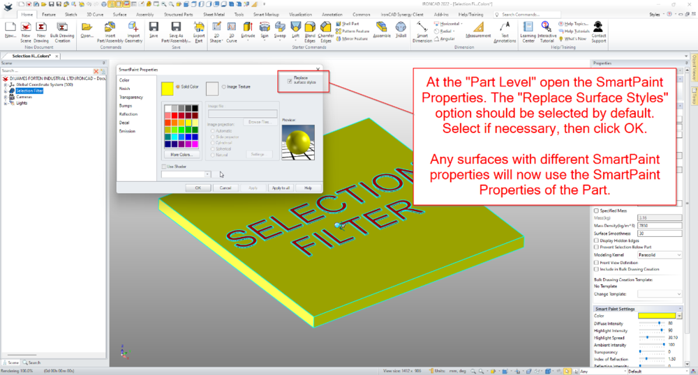
2 Q's: making a part smaller, remove "smart paint" settings
Malcolm Crowe replied to Gigi's topic in General Discussion
Hi Gigi, 1. Regarding editing of imported geometry, one of the options available is to use the "Direct Face Editing" tools. The link below is to a forum post with a new video demonstrating how to use the "Move Face" tool, and one of the examples involves lengthening and shortening an imported Hex Nipple. 2. To override SmartPaint properties that have been applied to faces, you need to select the Part (part level selection), then open the SmartPaint Properties dialog box. Once open, ensure that the "Replace Surface Styles" option is selected (in the top right corner), then click OK. The link below is to a forum post that includes a video demonstrating this (around the 4 min 30 sec mark). Malcolm- 1 reply
-
- 1
-

-
The attached video demonstrates how to use the "Move Face" and "Editing Face Radius" tools (along with some of the associated options) when editing imported geometry. Malcolm IRONCAD - Direct Face Modelling (Editing) - Hex Nipple and Bracket.mp4
-
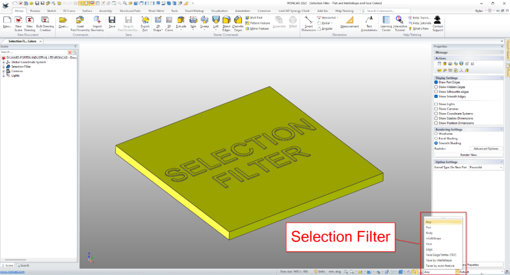
Selection Filter - Part and Intellishape and Face Colors
Malcolm Crowe replied to Malcolm Crowe's topic in Tips and Tricks
Hi Kim. You did well applying the principles from my video in your own engraving example. Good job! Malcolm -
Hi David, You might find this post in the "Tips" forum helpful. Malcolm
-
Within the 3D Scene of IRONCAD it's possible to apply different colors at the Part, Intellishape, and Face levels. This is especially helpful when working with multi-bodied (structured) parts, but also for highlight elements such as embossing or engraving. Located on the Status Bar (bottom right of the screen) is the "Selection Filter". This is useful for controlling what is selected during "box selections"; but it also includes useful filters such as "Faces by Intellishape" and "Faces by Auto-Feature". The attached video demonstrates how these filters can be used for selecting different elements, while also demonstrating how to apply different colors at the Part, Intellishape, and Face levels. Malcolm IRONCAD - Selection Filter - Part and Intellishape and Face Colors.mp4
-
Set Scene to Parasolid Kernel before Exporting
Malcolm Crowe replied to Malcolm Crowe's topic in Tips and Tricks
I don't know when this changed, but IRONCAD now exports and imports the assembly structure correctly within a STEP file regardless of the scene kernel selected. Malcolm -
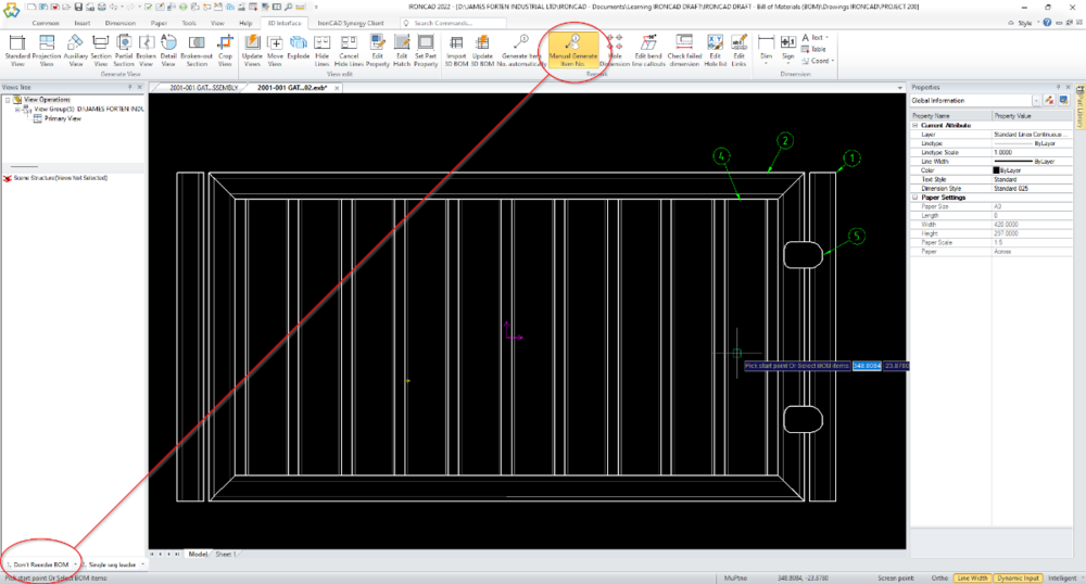
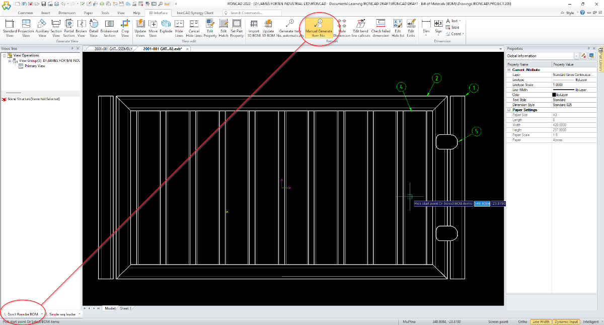
Hi Ramogale, Attached is an updated 10 minute video with audio (explaining what I'm doing). Around the 7 minute mark there is information regarding merging (if necessary) and reordering of the BOMs to ensure that the Model and Layout versions are the same. Within the "Fill in BOM" dialog box there are tools for reordering (merging, hiding, etc...) The other thing to be aware of is an option (at the bottom left of the screen) when using the Item Number tool. Be sure that this is set to "Don't Reorder BOM". CAXA should then remember your selection next time. If this option isn't selected CAXA will reorder the BOM based on the order that you place the Item Numbers. Malcolm CAXA - BOM - Matching Model and Layout Tabs.mp4
-
Sheet Metal Loft - Corner Reliefs - Missing in Unfolded
Malcolm Crowe replied to Malcolm Crowe's topic in General Discussion
Thanks Cary -
Attached are images of a Sheet Metal Lofted Part. When folded the Corner Reliefs are shown. When unfolded, the Corner Reliefs are missing. Why is that? Malcolm Sheet Metal Loft - Corner Reliefs.ics


-
Patterns in Caxa Draft when creating a Standard View
Malcolm Crowe replied to PatrickB's topic in General Discussion
Hi Patrick, Kevin is correct in saying that the Hatching automatically created as part of a Generated View requires that View to be a Sectioned View. However, it is possible to manually add Hatching inside a Generated View afterwards. This capability is very useful. For example, attached is an image where different Hatch Patterns have been applied within a Generated View to differentiate between different wall constructions. CAXA DRAFT is a DWG Editor, and the Generated Views are "Blocks" that can be edited in "Block Editing Mode". Attached is a video in which I add a "Dots" Hatch Pattern to the Slab and then a regular "Diagonal" Hatch Pattern to the Posts. Hopefully that gives you some idea of what is possible. Malcolm IRONCAD DRAFT - Adding Hatching to a Generated View (Block Editing).mp4.thumb.png.923c0b836a64f9830e1740e420c7aae5.png)
-1.thumb.png.fe439dac1714e9fcc3006dd2fd708cd1.png)
-
Adding to what Kevin has shown above, the "Style Manager" within the 3D Scene has been adopted from CAXA DRAFT. As a result, if you're familiar with using "Style Manager" and Annotations within CAXA DRAFT then it makes it easier to understand how to use "Style Manager" and PMI Annotations within the 3D Scene as well. Not only that, but you can also import existing "Styles" from CAXA DRAFT drawings into the 3D Scene (just as you can between 2D Drawings). The attached video demonstrates how to do similar things with PMI in the 3D Scene that can be done within CAXA DRAFT. Malcolm IRONCAD - PMI - Style Manager.mp4
-
Since the introduction of CAXA DRAFT 2022 there has been a problem with Center Mark Extension Lines scaling whenever a Generated View Regenerates. Attached is a video created back in March demonstrating this problem in SP1, and I've also attached a video demonstrating it in PU1. Essentially, when CAXA initially generates Center Marks on holes, the Extensions Lines created are correct. However, when the View is regenerated (such as when a change has been made to the 3D model), then any existing Center Marks will be resized based on the scale of the View. If a new hole is added to the 3D model, when the View is regenerated in CAXA, the newly generated Center Mark will be correct, but any existing Center Marks will incorrectly resize. The end result being that Views have Center Marks Extension Lines of different sizes. This is an extremely annoying problem. As a result we currently need to disable the automatic generation of Center Marks, and place manually using the Center Line tool. Malcolm CAXA 2022 PU1 - Center Mark Extensions are Scaling when Views Regenerate.mp4 IRONCAD 2022 SP1 - Center Mark Extensions are Scaling when Views Regenerate.mp4


-
Import/Export - STEP AP242 Format (.stp)
Malcolm Crowe replied to Malcolm Crowe's topic in General Discussion
Another reminder regarding this significant file format. Malcolm

inColor.png.54ee5deb669b162dfcfc457cee4f053d.png)
inColor.png.f978dd392b40defe437bce7900a665b3.png)


.png.dbb236e3743d56a0c0d047ab22779f10.png)
-1.png.8e4c36218bd5bf1a97c294362cd46879.png)
