
Jonas@Solidmakarna
-
Posts
2,287 -
Joined
-
Last visited
Content Type
Profiles
Forums
Blogs
Downloads
Articles
Gallery
Everything posted by Jonas@Solidmakarna
-
If the "scene container" (model geometry + all "other" ics file data) is the reason for the issue in some way you can always insert the ics file (no link) into a new ics file to remove old junk. Or "jump" to/from a catalog into a new scene. Kind of a purge function.
-
Hi Eric, In some cases with bad brep models exporting to IGES (as solid) and importing that file again can solve solid-to-surface issues. I guess the IGES format is to "dumb" to understand the tolerance issues and just makes a solid. Not always working but incredibly often. Your using Windows 7 Home, not "officially" supported. I don't think it is the issue in this case, but if you could try on a Windows 7 Professional/Ultimate (which probably also has another cpu) that might be worth trying out. As Dragan says you should also try the Combine Shapes tool under the Tools Ribbon tab (old UI under the Shape menu) which will combine all none suppressed features for the selected part into one brep shape (or the selected features into one shape). I would do that instead of exporting, then if it doesn't help export to IGES as solid and import again. Remember to make the import twice and switch to Parasolid/ACIS under the IC Options before importing the second time since the IGES file might be treated differently by the two kernels during import. I hope you'll find a way.
-
Importing a .dwg into 2D sketch
Jonas@Solidmakarna replied to rmiller587787's topic in General Discussion
When I import the dwg file into the empty sketch there are red points between each line, indicating that the lines are not properly connected. I know from older similar cases that I probably can't extrude it directly, but I have also seen that Finishing the sketch and then creating a new part from that sketch seems to "sew" the lines together automatically, which it did in this case (for me). I tried the Clear Duplicate tool, but there are no duplicate lines at all. There have been problems with imported dwg/dxf files containing splines throughout the years, but I think it has been working very well in the latest versions. Can you open the file I attached in the previous post? -
Importing a .dwg into 2D sketch
Jonas@Solidmakarna replied to rmiller587787's topic in General Discussion
Hi, If you import it into a new and empty 2D Shape, then use the Extrude tool to create a new part from that 2D Shape it seems to be working fine. Have you got Product Update 1 for v2013 installed, or which version are you using? Superheroes.ics -
Hi Tom, How about CTRL ALT (SHIFT) selecting? Might be many clicks in this case though... Edit: Combined with using transparency on the part would make it easier. I use this from time to time, specially during trainings to show that it is possible. Also (kind of off topic) combined with Show hidden edges, being able to select edges through parts.
-
I saw a strange thing on a Dell Prec M6500 or if it was a M6700 today. When setting the external screen as the "primary screen" the graphic issues that we saw disappeared. So try connecting an external screen and set it as primary and see if it works any better. Edit: It had a FireGL card too, 7820 or 7580 or whatever the numbers after 7xxx were.
-
Middle Mouse button Controls?
Jonas@Solidmakarna replied to tlehnhaeuser's topic in General Discussion
I'm glad you found it Tom. But I think the Mouse section under the Options should be changed back to be shown on its own and not as a sub menu for the Interaction options. -
Using Configurations with externally linked parts.
Jonas@Solidmakarna replied to Karen Bond's topic in General Discussion
Hi Karen, At the moment I don't think IC supports the use of different configurations from the same file in a scene. You can easily change the current configuration by a right mouse click on the "path" icon under the part/assembly in the Scene Browser. But all other copies of that file in that scene will update accordingly. -
Cool! Then I take back what I said about "final", don't think it gets more done than that!
-
I think it goes public in the end of this month. I don't think the "final" version is out yet.
-
Here's another option: http://lee-soft.com/vistart/
-
Here's a pretty good tool for those of you who want the "good old" start menu back, but also a lot more stuff that has been removed over the years. I haven't tried it myself, but I will probably install it when I run Win 8 in the future... http://classicshell.sourceforge.net/
-
Hi Tom, There is no Part Number set on the Parts in the scene? The BOM and the Item Bubbles always reads from the parts, if you manually add the Part Number in the BOM you must transfer it, but then it will be transfered as a Custom Property... You should always set at least one parts Part Number in the scene, then the rest will work fine. So, in the scene, select the parts and add the Part Number. Now, the Item Bubbles will show the Part Number set on the parts in the scene. But the BOM will still show the values you've manually typed in the BOM, since they're added as Custom Properties.
-
Thanks Dragan! Really well done!
-
Hi Tom, Did you update the view after the change? Most changes in the BOM doesn't apply until an update. Second, you should always use the same configuration as the one that the view is using, in this case - change from "no configuration selected" to "default". This is very important in general! The "no configuration selected" (or "whole" in caxa) is one of my biggest dislikes... should be renamed "include suppressed objects" and not be set as the default option. Cary, is there any other way to get the Part Number shown in the BOM other than manually typing it as a custom prop? There's no specific option for Part Number and Description. It has always worked out fine to manually type it (or as you said, add it in the custom list).
-
That's true, I forgot to mention that you just have to manually type "Part Number". It's important that you don't type "part number", "PartNumber" or "Part number" or similar.
-
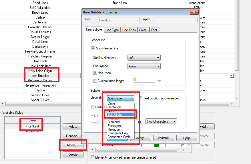
For the item Bubbles to show the Upper/Lower split value you must go to the Styles and Layers (or a single Item Bubble). Select Item Bubbles, the Style setting and the change the "Geometry" setting to Split Circle. I don't think any of the other settings can show split values.
-
Hello Brian, At the moment the decimals are controlled by the decimal setting in the Tools/Options General Tab (precision displayed in dialogs).
-
Hello Wim, It should work even if it's not selected first, even if selecting it first works fine too. After a SmartDimension is applied you can always select the dimension text and a small black arrow appears next to the Dim Arrows. If you click on one of the small arrows (mouse symbol looks like a pointing finger). Then a little box appears where you can select which level that should be affected. The object with the red text is the one currently affected by the dimension. You can easily change by selecting another object in the list. Under Options, Interaction, there's a setting which is set to hold the selection when you apply SmartDimension - "Keep selected shape as affected/owning object when creating dimension". With that option selected the selection edge color will not drop when you select the SmartDimension tool and the assembly is selected.
-
Great work Yaroslav, thanks a lot for sharing this! I have been asked this a few times and never been able to solve it. Until now!!!
-
I was just told that we switched a Quadro 4000 card with a GTX 570 which solved several issues. I thought it was interesting for you to know.
-
Steve, If it is possible for you to make a test, it would be interesting to hear what you say about an Nvidia GeForce GTX card (660 or 690 for example). I know several cases where an Nvidia Quadro x000 has been outrun by a GeForce card! I don't know why, but the newer Quadro cards doesn't seem to run very well I'm afraid. In your case you have an older card which I know for certain had problems already when it was new back in 2008/2009! It had many strange problems with improper and unstable graphics compared with other cards. Though it is interesting to hear that it was working better in v2011 than now in v2012. Now, I'm not very good at the details and differences between the cards, but the new GTX cards really seems to be working fine. I've heard some comments about the "sharpness" or what you should call it, not being as good as for Quadro cards. But speed, yes. It is much cheaper too. Maybe you can have a "try out" from a friendly hardware dealer?
-
Adding other than Part/Assembly in catalog
Jonas@Solidmakarna replied to msaffiudin's topic in General Discussion
Hi, I think the easiest way is to copy and paste another existing image/texture icon and then edit the copy by choosing Edit Catalog item under the icon right click menu in the catalog. Browse to the image you want to use instead. An issue with that is that the icon won't update with the correct image. Instead: Place a texture on a part using the SmartPaint settings on the Part right click menu. Use the Fill EyeDropper tool under the Visualization ribbon bar to fetch the texture and place it inside the catalog. Now you'll have a new texture icon with the correct settings. -
Moving multiple parts into an existing assembly
Jonas@Solidmakarna posted a topic in Tips and Tricks
It is possible to move single parts and assemblies in and out from assemblies by dragging their icons in the scene browser structure. You can also move several of them at once by holding down the SHIFT or CTRL key while dragging and it is also very important that you drop on the target assembly icon (not on something that resides inside/below the target assembly). 1) Select the parts by using the CTRL or the SHIFT key. 2) Hold down the CTRL or the SHIFT key while dragging. 3) Drop on the target assembly icon. Now all selected parts have been moved to the selected assembly. See instructions here: Another trick is to make a temporary assembly of all the selected parts. Move the temporary assembly inside another assembly (target assembly). Disassemble the temporary assembly inside the target assembly. At the bottom of the target assembly you'll see all the moved parts. -
It would be good if the same was possible to do with sweeps. If the start point of the 3D curve is moved the cross-section follows. I guess the same options could be added in the PB when a sweep or a loft is created? Check ER #100159.